Page 1176 of 2893
����
��������
����
14-260Automatic Transmission
Shift Cable Adjustment (cont’d)
A
B
C
A B
C B
A
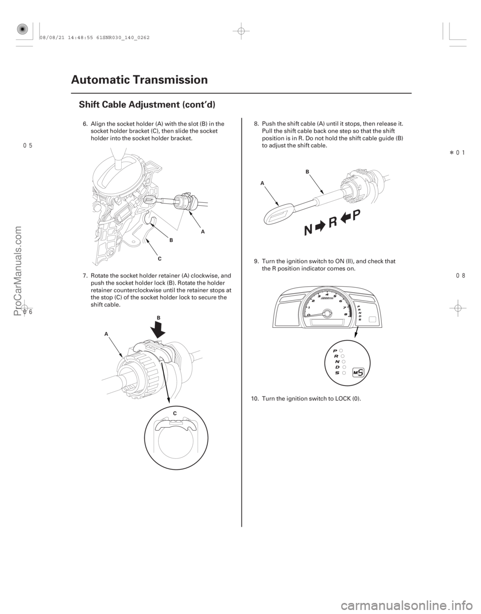
6. Align the socket holder (A) with the slot (B) in the socket holder bracket (C), then slide the socket
holder into the socket holder bracket.
7. Rotate the socket holder retainer (A) clockwise, and push the socket holder lock (B). Rotate the holder
retainer counterclockwise until the retainer stops at
the stop (C) of the socket holder lock to secure the
shift cable. 8. Push the shift cable (A) until it stops, then release it.
Pull the shift cable back one step so that the shift
position is in R. Do not hold the shift cable guide (B)
to adjust the shift cable.
9. Turn the ignition switch to ON (II), and check that the R position indicator comes on.
10. Turn the ignition switch to LOCK (0).
08/08/21 14:48:55 61SNR030_140_0262
ProCarManuals.com
DYNOMITE -2009-
Page 1178 of 2893
�
��
14-262Automatic Transmission
Shift Cable Adjustment (cont’d)
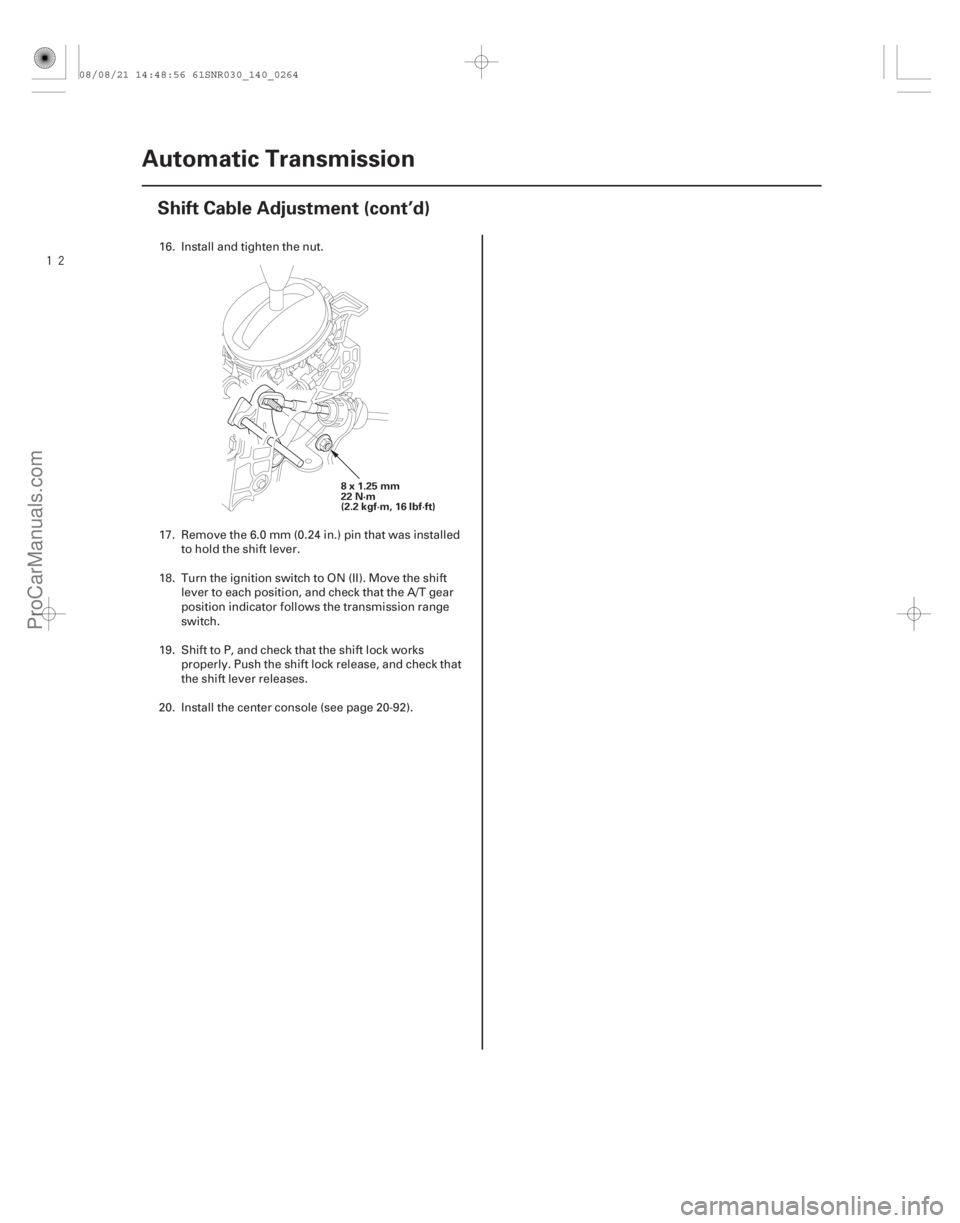
8x1.25mm
22 N·m
(2.2 kgf·m, 16 lbf·ft)
16. Install and tighten the nut.
17. Remove the 6.0 mm (0.24 in.) pin that was installed
to hold the shift lever.
18. Turn the ignition switch to ON (II). Move the shift lever to each position, and check that the A/T gear
position indicator follows the transmission range
switch.
19. Shift to P, and check that the shift lock works properly. Push the shift lock release, and check that
the shift lever releases.
20. Install the center console (see page 20-92).
08/08/21 14:48:56 61SNR030_140_0264
ProCarManuals.com
DYNOMITE -2009-
Page 1181 of 2893
����
�µ
Transmission Range Switch Subharness
Connector
14-265
Transmission Range Switch Test
A Connector Terminal/Signal
25
134
687910")
���
����
����
�(�#�'�������
���
�����
�����������
�
�������)����
�µ
Transmission Range Switch Subharness
Connector
14-265
Transmission Range Switch Test
A Connector Terminal/Signal
25
134
687910
P
R
N
D
S
Posi-
tion
6x1.0mm
12 N·m (1.2 kgf·m, 8.7 lbf·ft)
ATP
NP
ATP
FWD
GND
ATP
RVS
ATP
D ATP
R ATP
P ATP
SATP
N
1. Remove the intake air duct (see page 11-348) and
the air cleaner assembly (see page 11-345).
2. Disconnect the transmission range switch subharness connector (A).
3. Check for continuity between the terminals at the harness connector. There should be continuity
between the terminals in the following table for
each switch position. 4. Transmission range switch test has completed if
the test results are OK, go to step 12. If there is no
continuity between any terminals, go to step 5.
5. Raise the vehicle on a lift, or apply the parking brake, block the rear wheels, and raise the front of
the vehicle. Make sure it is securely supported.
6. Remove the transmission range switch cover.
(cont’d)
Terminal side of
male terminals
08/08/21 14:49:01 61SNR030_140_0267
ProCarManuals.com
DYNOMITE -2009-
Page 1183 of 2893
����
14-267
Transmission Range Switch Replacement
A B
C
D
1. Raise the vehicle on a lift, or apply the parking brake, block the rear")
���
��������
����
�(�#�'�������
���
�����
�����������
�
� �����)����
14-267
Transmission Range Switch Replacement
A B
C
D
1. Raise the vehicle on a lift, or apply the parking brake, block the rear wheels, and raise the front of
the vehicle. Make sure it is securely supported.
2. Move the shift lever to N.
3. Remove the transmission range switch cover.
4. Remove the transmission range switch. 5. Make sure the control shaft is in the N position. If
necessary, move the shift lever to N from P.
NOTE: Do not use the selector control shaft to
adjust the shift position. If the control shaft tips are
squeezed together it will cause a faulty signal or
position due to play between the selector control
shaft and the transmission range switch.
6. Align the cutouts (A) on the rotary-frame with the neutral positioning cutouts (B) on the transmission
range switch (C), then put a 2.0 mm (0.08 in.) feeler
gauge blade (D) in the cutouts to hold the switch in
the N position.
NOTE: Be sure to use a 2.0 mm (0.08 in.) blade or
equivalent to hold the switch in the N position.
(cont’d)
08/08/21 14:49:02 61SNR030_140_0269
ProCarManuals.com
DYNOMITE -2009-
Page 1185 of 2893
����
14-269
A/T Gear Position Indicator Panel Light Harness/Park Pin Switch
Replacement
A
B B
C
D
E F
G
A
NOTE: The A/T gear position indicato")
���
����
�(�#�'�������
���
�����
�����
��������� �����)����
14-269
A/T Gear Position Indicator Panel Light Harness/Park Pin Switch
Replacement
A
B B
C
D
E F
G
A
NOTE: The A/T gear position indicator light and the park
pin switch are not available separately. Replace the A/T
gear position indicator light and the park pin switch as a
set. 1. Remove the shift lever assembly (see page 14-254).
2. Loosen the A/T gear position indicator panel (see page 14-256).
3. Remove the park pin switch (A) while pressing the park pin switch lock (B). 4. Remove the A/T gear position indicator panel light
bulb (A) and the socket (B) from the indicator panel
(C), and remove the light bulb from the socket.
5. Remove the harness clamp (D), and remove the park pin switch/A/T gear position indicator panel
light connector (E) from the shift l ever assembly/
bracket base (F).
6. Install a new park pin switch (G) on the shift lever.
7. Install the A/T gear position indicator panel light bulb in a new socket, and install it in the indicator
panel.
8. Clamp the harnesses together with the harness clamp, then install the harness clamp on the shift
lever bracket base.
9. Route the harnesses along the harness guides, and install a new connector in the bracket base.
10. Install the A/T gear position indicator panel (see page 14-256).
11. Install the shift lever assembly (see page 14-255).
12. Install the center console (see page 20-92).
08/08/21 14:49:58 61SNR030_140_0271
ProCarManuals.com
DYNOMITE -2009-
Page 1186 of 2893
����
14-269
A/T Gear Position Indicator Panel Light Harness/Park Pin Switch
Replacement
A
B B
C
D
E F
G
A
NOTE: The A/T gear position indicato")
���
����
�(�#�'�������
���
�����
�����
��������� �����)����
14-269
A/T Gear Position Indicator Panel Light Harness/Park Pin Switch
Replacement
A
B B
C
D
E F
G
A
NOTE: The A/T gear position indicator light and the park
pin switch are not available separately. Replace the A/T
gear position indicator light and the park pin switch as a
set. 1. Remove the shift lever assembly (see page 14-254).
2. Loosen the A/T gear position indicator panel (see page 14-256).
3. Remove the park pin switch (A) while pressing the park pin switch lock (B). 4. Remove the A/T gear position indicator panel light
bulb (A) and the socket (B) from the indicator panel
(C), and remove the light bulb from the socket.
5. Remove the harness clamp (D), and remove the park pin switch/A/T gear position indicator panel
light connector (E) from the shift l ever assembly/
bracket base (F).
6. Install a new park pin switch (G) on the shift lever.
7. Install the A/T gear position indicator panel light bulb in a new socket, and install it in the indicator
panel.
8. Clamp the harnesses together with the harness clamp, then install the harness clamp on the shift
lever bracket base.
9. Route the harnesses along the harness guides, and install a new connector in the bracket base.
10. Install the A/T gear position indicator panel (see page 14-256).
11. Install the shift lever assembly (see page 14-255).
12. Install the center console (see page 20-92).
08/08/21 14:49:58 61SNR030_140_0271
ProCarManuals.com
DYNOMITE -2009-
Page 1189 of 2893
 Circuit Troubleshooting (cont’d)
CABLE REEL 20P CONNECTOR
SUPP (BLU)
JUMPER WIRE PCM CONNECTOR B (4")
����������
�µ
�µ
YES
NO
14-272 A/T Gear Position Indicator
Paddle Shifter + (Upshift Switch) Circuit Troubleshooting (cont’d)
CABLE REEL 20P CONNECTOR
SUPP (BLU)
JUMPER WIRE PCM CONNECTOR B (44P)
SUPP (BLU/YEL)
10. Turn the ignition switch to LOCK (0).
11. Jump the SCS line with the HDS.
12. Disconnect PCM connector B (44P).
13. Connect cable reel 20P connector terminal No. 16 and body ground with a jumper wire. 14. Check for continuity between PCM connector
terminal B16 and body ground.
Check for poor connections or loose
terminals between cable reel 20P connector
terminal No. 16 and PCM connector terminal B16. If
the connection is OK, update the PCM if it does not
have the latest software (see page 11-227), or
substitute a known-good PCM (see page 11-7), then
recheck. If the symptom goes away with a known-
good PCM, replace the original PCM (see page
11-228).
Repair open in the wire between PCM
connector terminal B16 and the cable reel 20P
connector.
Wire side of female terminals Terminal side of female terminals
Is there continuity?
08/08/21 14:50:00 61SNR030_140_0274
ProCarManuals.com
DYNOMITE -2009-
Page 1192 of 2893

JUMPER WIRE PCM CONNECTOR B (44P)
SDNP (BRN)
10. Turn the ignition switch to LOCK (0).
11. Jump the SCS line with the HDS.
12.")
����������
�µ
�µ
YES
NO
14-275
CABLE REEL 20P CONNECTOR
SDNP (GRN)
JUMPER WIRE PCM CONNECTOR B (44P)
SDNP (BRN)
10. Turn the ignition switch to LOCK (0).
11. Jump the SCS line with the HDS.
12. Disconnect PCM connector B (44P).
13. Connect cable reel 20P connector terminal No. 17and body ground with a jumper wire. 14. Check for continuity between PCM connector
terminal B40 and body ground.
Check for poor connections or loose
terminals between cable reel 20P connector
terminal No. 17 and PCM connector terminal B40. If
the connection is OK, update the PCM if it does not
have the latest software (see page 11-227), or
subsitute a known-good PCM (see page 11-7), then
recheck. If the symptom goes away with a known-
good PCM, replace the original PCM (see page
11-228).
Repair open in the wire between PCM
connector terminal B40 and the cable reel 20P
connector.
Wire side of female terminals Terminal side of female terminals
Is there continuity?
08/08/21 14:50:01 61SNR030_140_0277
ProCarManuals.com
DYNOMITE -2009-