Page 2144 of 2893
�
�
22-194Interior Lights
Circuit Diagram
D A
B
A C
GRNMICU
UNDER-DASH FUSE/RELAY BOX
GRNE37 E3
LT GRN BRNE17 E2
GRYK4
(8 W) (8 W)
1
(Without moon")
������(�#�'���������������������������������������)�
�
22-194Interior Lights
Circuit Diagram
D A
B
A C
GRNMICU
UNDER-DASH FUSE/RELAY BOX
GRNE37 E3
LT GRN BRNE17 E2
GRYK4
(8 W) (8 W)
1
(Without moonroof)
LT BLU
PNKDOOR
OFF
PNK
BLU
3
LT BLU LT BLU
LT BLU
(With moonroof)
1
2
(8 W) (8 W)
PNK 1
ON OFF
(8 W) RED
UNDER-HOOD FUSE/RELAY BOX
No. 22 (7.5 A)
No. 1 (BAT) (100 A)
BATTERY
CEILING
LIGHT
INTERIOR
LIGHT SWITCH
(In the moonroof
switch)
RIGHT REAR
DOOR
SWITCH
(Closed:
Door open)
LEFT REAR
DOOR
SWITCH
(Closed:
Door open)
FRONT
PASSENGER’S
DOOR SWITCH
(Closed:
Door open)
DRIVER’S
DOOR
SWITCH
(Closed:
Door open) D2
1 1
1
9*2 8*1
1*1
7*2 LT BLU
LT BLU
FRONT
PASSENGER’S
DOOR
COURTESY
LIGHT LT BLU
VANITY
MIRROR
LIGHTS *2
No. 22 (7.5 A)FUSE
(UNDER-HOOD
FUSE/RELAY BOX) LT BLU
GRN (3.4 W)
DRIVER’S
DOOR
COURTESY
LIGHT
GRN1 No. 22 (7.5 A)FUSE
(UNDER-HOOD
FUSE/RELAY BOX)
LT GRN
GRN (3.4 W)
FRONT
PASSENGER’S
DOOR
COURTESY
LIGHT BLU
BLK 3
2
G701 E36
BLU TRUNK LID
LATCH
SWITCH
(Closed:
Trunk lid open)BLU
TRUNK
LIGHT
FRONT
INDIVIDUAL
MAP LIGHTS
FRONT
INDIVIDUAL
MAP LIGHTS
08/08/21 14:27:49 61SNR030_220_0196
ProCarManuals.com
DYNOMITE -2009-
Page 2145 of 2893

LT BLU
BLK GRY
GRY GRY
RED
(5 W)
1
WHT
2
(LED)
GRN
G502 AMBIENT
LIGHT
DASH LIGHTS
BRIGHTNESS
CONTROLLER TRUNK
LIGHT
UNDER-DASH")
�����
�µ
�µ
�µ
�µ
22-195
R10LT BLU
K5
G3
E38
CLOSE OPEN
1
2 (3.4 W)
LT BLU
BLK GRY
GRY GRY
RED
(5 W)
1
WHT
2
(LED)
GRN
G502 AMBIENT
LIGHT
DASH LIGHTS
BRIGHTNESS
CONTROLLER TRUNK
LIGHT
UNDER-DASH
FUSE/RELAY BOX
No. 14 (7.5 A) FUSE
(UNDER-DASH
FUSE/RELAY BOX) GLOVE
BOX
LIGHTGLOVE
BOX
LID
GRY
(LED)
RED 2 1
DRIVER’S
FOOTWELL
LIGHT
DASH LIGHTS
BRIGHTNESS
CONTROLLER
GRY
(TYPE S model)
BLU
DRIVER’S
DOOR
COURTESY
LIGHT
TRUNK LID
LATCH
SWITCH
GRY(LED)
RED 2 1
FRONT
PASSENGER’S
FOOTWELL
LIGHT
DASH LIGHTS
BRIGHTNESS
CONTROLLER
LT BLU
DRIVER’S
VANITY
MIRROR
LIGHT
SWITCH
DRIVER’S
VANITY
MIRROR
LIGHT (2 W)DRIVER’S
SUNVISOR
1
2 LT BLU
PASSENGER’S
VANITY
MIRROR
LIGHT
SWITCH
PASSENGER’S
VANITY
MIRROR
LIGHT (2 W)PASSENGER’S
SUNVISOR
1
2
G502 BLK *2
BLK BLK
No. 22 (7.5 A) FUSE
(UNDER-HOOD
FUSE/RELAY BOX)
C
D B
5*3
4*4
3*2
2*2
5*4
3*3 *1: ’06 07 models
*2: ’08 09 models
*3: ’06 07 models with moonroof
*4: ’06 07 models without moonroof
08/08/21 14:27:49 61SNR030_220_0197
ProCarManuals.com
DYNOMITE -2009-
Page 2152 of 2893
����
�(�#�'���������������������������������������)����
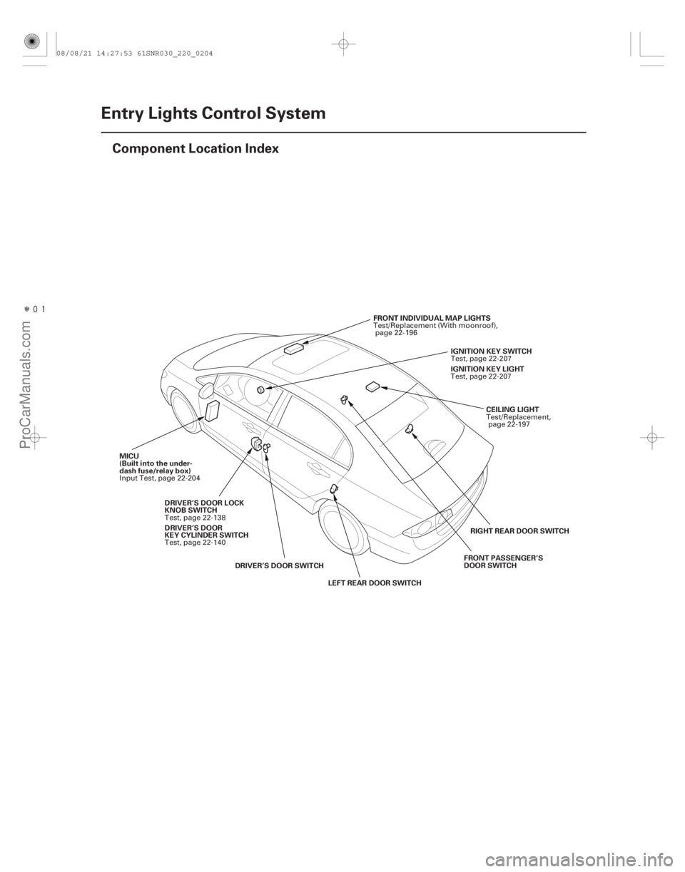
22-202Entry Lights Control System
Component Location Index
CEILING LIGHT
FRONT INDIVIDUAL MAP LIGHTS
MICU
(Built into the under-
dash fuse/relay box) IGNITION KEY SWITCH
DRIVER’S DOOR SWITCH LEFT REAR DOOR SWITCH RIGHT REAR DOOR SWITCH
FRONT PASSENGER’S
DOOR SWITCH
DRIVER’S DOOR LOCK
KNOB SWITCH IGNITION KEY LIGHT
DRIVER’S DOOR
KEY CYLINDER SWITCH Test/Replacement,
page 22-197
Test/Replacement (With moonroof),
page 22-196
Input Test, page 22-204 Test, page 22-207
Test, page 22-138 Test, page 22-207
Test, page 22-140
08/08/21 14:27:53 61SNR030_220_0204
ProCarManuals.com
DYNOMITE -2009-
Page 2153 of 2893
����
�µ
�µ
22-203
Circuit Diagram
5 6
R13
ORN
LT BLU
BLK5
7
G501 LOCK
WHT
T23
BRN T24
LT GRN
6
4
UNDER-DASH FUSE/RELAY BOX 7*2
1*1 8*1
9*2K5
G3 D")
����
�(�#�'���������������������������������������)����
�µ
�µ
22-203
Circuit Diagram
5 6
R13
ORN
LT BLU
BLK5
7
G501 LOCK
WHT
T23
BRN T24
LT GRN
6
4
UNDER-DASH FUSE/RELAY BOX 7*2
1*1 8*1
9*2K5
G3 D2
PG
SG
PNKR16
G501 BLK
T34
BLK
G401 F20
E2
GRY
LT BLU LT BLU
CEILING LIGHT BLU
PNK FRONT
INDIVIDUAL
MAP LIGHTS
PNKDOOR
IG1Q6
B-CAN
No. 22 (7.5 A)
No. 2 (IG) (50 A)
No. 1 (BAT) (100 A)
OFFUNDER-DASH FUSE/RELAY BOX
(7.5 A) No. 10
PNK
PNK RED
BLU
BRN E17
E33 R6
G601 BLK
E6
BLK
G602 K4
MICU
E3
E37
GRN LT GRN
G504BLKPNK
1
2
WHT
IG1
BAT
UNDER-HOOD FUSE/RELAY BOX
BATTERY IGNITION SWITCH
IG1 HOT in ON (II)
and START (III)
INTERIOR
LIGHT
SWITCH IMMOBILIZER-
KEYLESS CONTROL
UNIT
DRIVER’S
DOOR
SWITCH
(Closed:
Door open) FRONT
PASSENGER’S
DOOR SWITCH
(Closed:
Door open) LEFT
REAR DOOR
SWITCH
(Closed:
Door open)RIGHT
REAR DOOR
SWITCH
(Closed:
Door open) IGNITION
KEY
SWITCH
(Closed:
Key inserted)IMMOBILIZER-
KEYLESS
CONTROL
UNIT
DRIVER’S
DOOR
LOCK
KNOB
SWITCH
UN-
LOCK
IGNITION
KEY LIGHT
(LED)
H1
D2
1 111 :CANline
*1: ’06 07 models
*2: ’08 09 models
TRANSMITTER
08/08/21 14:27:54 61SNR030_220_0205
ProCarManuals.com
DYNOMITE -2009-
Page 2154 of 2893
���
�(�#�'�������������������������
�����
�������)����
22-204Entry Lights Control System
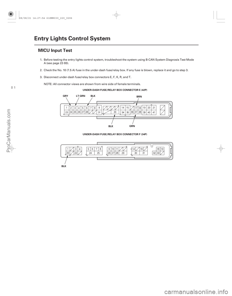
MICU Input Test
UNDER-DASH FUSE/RELAY BOX CONNECTOR E (42P)
BLK BRN
GRY
UNDER-DASH FUSE/RELAY BOX CONNECTOR F (34P) BLK
BLK LT GRN
GRN
1. Before testing the entry lights control system, troubleshoot the system using B-CAN System Diagnosis Test ModeA (see page 22-93).
2. Check the No. 10 (7.5 A) fuse in the under-dash fuse/relay box. If any fuse is blown, replace it and go to step 3.
3. Disconnect under-dash fuse/relay box connectors E, F, K, R, and T. NOTE: All connector views are shown from wire side of female terminals.
08/08/21 14:27:54 61SNR030_220_0206
ProCarManuals.com
DYNOMITE -2009-
Page 2155 of 2893

PNK
WHT BLK
PNK
UNDER-DASH FUSE/RELAY BOX
CONNECT")
����Cavity Wire Test condition Test: Desired result Possible cause if desired result is not obtained
22-205
UNDER-DASH FUSE/RELAY BOX
CONNECTOR K (8P)
PNK
WHT BLK
PNK
UNDER-DASH FUSE/RELAY BOX
CONNECTOR R (20P)
UNDER-DASH FUSE/RELAY BOX
CONNECTOR T (34P)
4. Inspect the connector and socket terminals to be sure they are all making good contact. If the terminals are bent, loose or corroded, repair them as necessary and recheck the system.
IftheterminalslookOK,gotostep5.
5. With the connectors still disconnected, do this input test at the following connector. If any test indicates a problem, find and correct the cause, then recheck the system.
If all the input tests prove OK, go to step 6.
K4 PNK With the ceiling light
switch in the middle
position
With moonroof:
with the interior light
switch in DOOR
position Attach to ground:
The ceiling light and front
individual map lights should
come on.
Blown No. 22 (7.5 A) fuse in
the under-hood fuse/relay
box
Blown bulb(s)
Faulty ceiling light
Faulty front individual map
light
Faulty interior light switch
(with moonroof)
An open in the wire
(cont’d)
08/08/21 14:27:54 61SNR030_220_0207
ProCarManuals.com
DYNOMITE -2009-
Page 2156 of 2893

6. Reconnect the connectors to the under-da")
Cavity WireTest condition Test: Desired result Possible cause if desired result is not
obtained
22-206Entry Lights Control System
MICU Input Test (cont’d)
6. Reconnect the connectors to the under-dash fuse/relay box, and do these input tests at the following connectors.
If any test indicates a problem, find and correct the cause, then recheck the system.
If all the input tests prove OK, the MICU must be faulty; replace the under-dash fuse/relay box.
E6 BLK Under all conditions Measure the voltage to ground:
There should be less than 0.5 V.Poor ground (G602)
An open in the wire
E33 BLK Under all conditions Measure the voltage to ground: There should be less than 0.5 V.Poor ground (G601)
An open in the wire
F20 BLK Under all conditions Measure the voltage to ground: There should be less than 0.5 V.Poor ground (G401)
An open in the wire
T34 BLK Under all conditions Measure the voltage to ground: There should be less than 0.5 V.Poor ground (G501)
An open in the wire
E37 GRN Driver’s door open Measure the voltage to ground: There should be less than 1 V.Faulty driver’s door switch
An open in the wire
Driver’s door closed Measure the voltage to ground: There should be more than 5 V. Faulty driver’s door switch
A short to ground in the wire
E3 LT GRN Front passenger’s door open Measure the voltage to ground: There should be less than 1 V.Faulty front passenger’s door switch
An open in the wire
Front passenger’s door closed Measure the voltage to ground: There should be more than 5 V. Faulty front passenger’s door switch
A short to ground in the wire
E2 GRY Right rear door open Measure the voltage to ground: There should be less than 1 V.Faulty right rear door switch
An open in the wire
Right rear door closed Measure the voltage to ground: There should be more than 5 V. Faulty right rear door switch
A short to ground in the wire
E17 BRN Left rear door open Measure the voltage to ground: There should be less than 1 V.Faulty left rear door switch
An open in the wire
Left rear door closed Measure the voltage to ground: There should be more than 5 V. Faulty left rear door switch
A short to ground in the wire
R6 PNK Ignition key inserted into the ignition switch Measure the voltage to ground:
There should be less than 1 V. Poor ground (G504)
Faulty ignition key switch
An open in the wire
Ignition switch OFF and ignition
key removed from the ignition
switch Measure the voltage to ground:
There should be more than 5 V.
Faulty ignition key switch
A short to ground in the wire
T23 WHT Driver door lock knob switch unlocked Measure the voltage to ground:
There should be less than 1 V. Poor ground (G501)
Faulty driver door lock knob switch
An open in the wire
Driver door lock knob switch
locked Measure the voltage to ground:
There should be more than 5 V. Faulty driver door lock knob switch
A short to ground in the wire
08/08/21 14:27:54 61SNR030_220_0208
ProCarManuals.com
DYNOMITE -2009-
Page 2158 of 2893
����
�(�#�'���������������������������������������)����
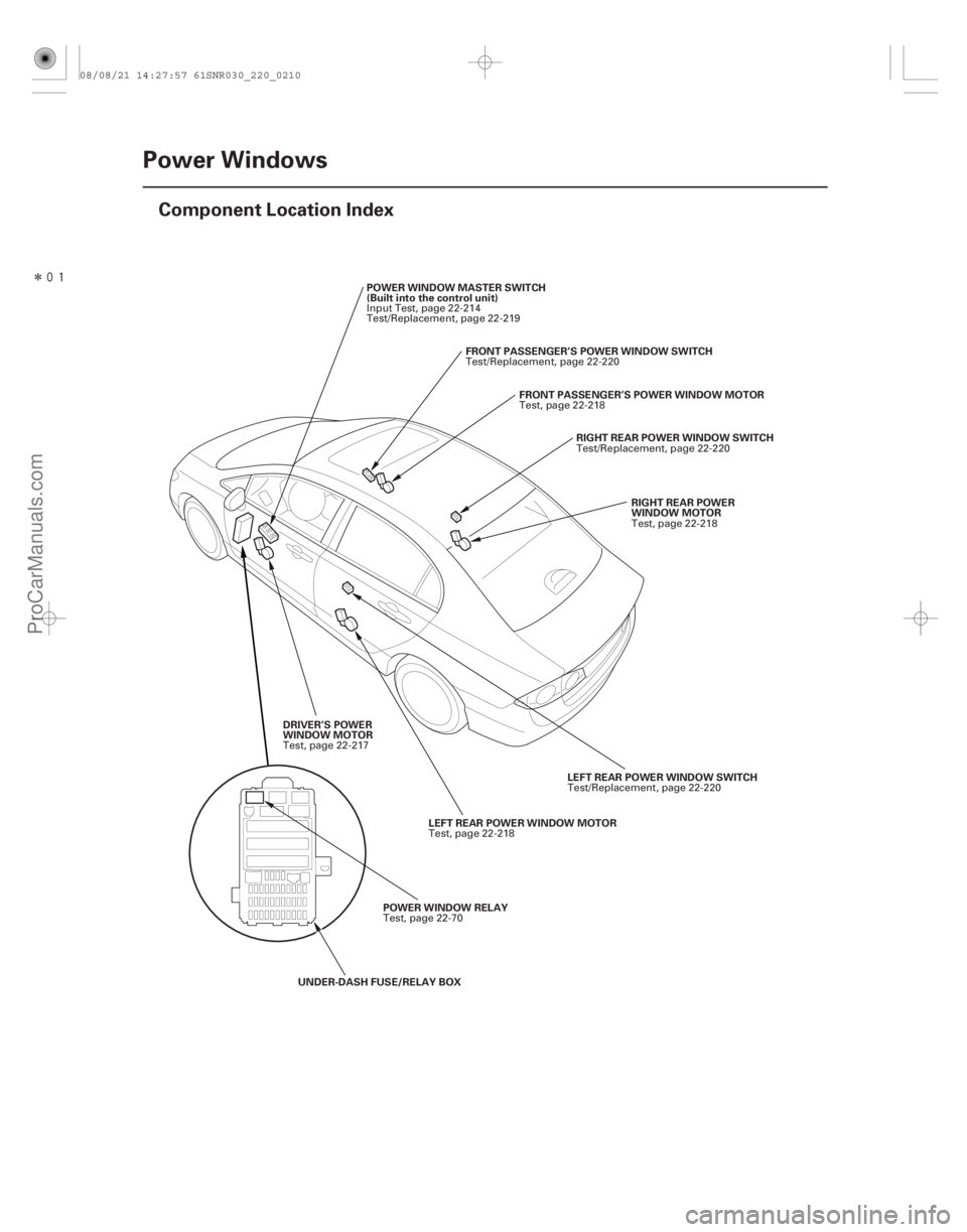
22-208Power Windows
Component Location Index
RIGHT REAR POWER
WINDOW MOTOR
RIGHT REAR POWER WINDOW SWITCH
FRONT PASSENGER’S POWER WINDOW MOTOR
FRONT PASSENGER’S POWER WINDOW SWITCH
POWER WINDOW MASTER SWITCH
(Built into the control unit)
LEFT REAR POWER WINDOW SWITCH
LEFT REAR POWER WINDOW MOTOR
DRIVER’S POWER
WINDOW MOTOR
POWER WINDOW RELAY
UNDER-DASH FUSE/RELAY BOX Test, page 22-218
Test/Replacement, page 22-220
Test, page 22-218
Test/Replacement, page 22-220
Input Test, page 22-214
Test/Replacement, page 22-219
Test/Replacement, page 22-220
Test, page 22-218
Test, page 22-217
Test, page 22-70
08/08/21 14:27:57 61SNR030_220_0210
ProCarManuals.com
DYNOMITE -2009-