Page 2100 of 2893
������(�#�'�����!���������
�����
�����������������)�
��
�´
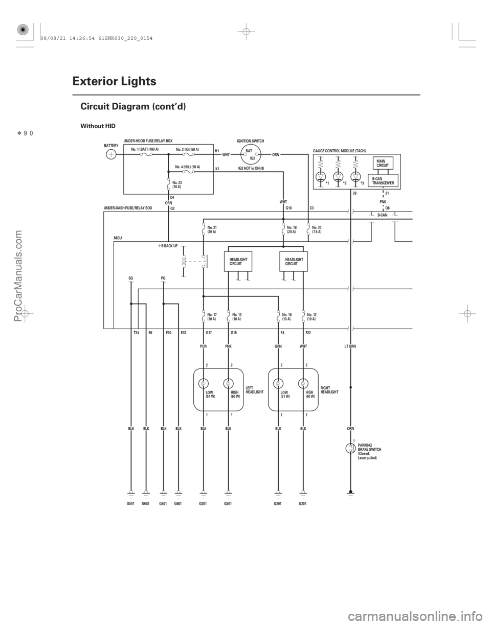
Without HID
22-152Exterior Lights
Circuit Diagram (cont’d)
G18
G501 BLKSG
T34 E6
G602BLK *3
*2
*1
IG2 HOT in ON (II) GAUGE CONTROL MODULE (TACH)
B-CANPNK
Q6 21
28
ORN
LT GRN
ORN
WHT
IG2
BAT
IGNITION SWITCH
No. 2 (IG) (50 A)
G2
BLK
BLK
BLK
BLK
BLK WHT
G601 E33
F20
PG
BLK
G401 BBACKUP
MICU ORNNo. 4 (H/L) (50 A)
G301 G201 F22
F4
G15
G17
2
2
11
1 2
1
2
G201
G301 GRN WHT
PUR
UNDER-DASH FUSE/RELAY BOX
UNDER-HOOD FUSE/RELAY BOX
PNK
No. 1 (BAT) (100 A)
BATTERY
RIGHT
HEADLIGHT
LEFT
HEADLIGHT MAIN
CIRCUIT
B-CAN
TRANSCEIVER
PARKING
BRAKE SWITCH
(Closed:
Lever pulled)
H1
K1
D4
1
C3
HEADLIGHT
CIRCUIT HEADLIGHT
CIRCUIT
No. 23
(10 A)
No. 21
(20 A) No. 18
(20 A)No. 37
(7.5 A)
No. 17
(10 A) No. 13
(10 A) No. 16
(10 A)No. 12
(10 A)
LOW
(51 W) HIGH
(60 W)
LOW
(51 W)HIGH
(60 W)
08/08/21 14:26:54 61SNR030_220_0154
ProCarManuals.com
DYNOMITE -2009-
Page 2101 of 2893
�����
22-153
1
BLK
G301 2
RED
RED REDRED
2 1
G201 BLK 1
2
2
4
G701
G701 MICU
9
1
2
RED
RED
BLK BLK S1
ORN
BLK BLK
BLK
BLK
BLK
BLK
BLK RED
RED
RED
RED S5
S11
S13
S12
S16
BLK
PNK
GRY
RED
LT BLU
G701
E19
RED
F3
RED
G201 RED
G301 BLK
G701
G701 G701
1
2
4
2 2
12
11
2
RED
G5
12
(
()
1011
6
4
)
OFF
LO
HI
DIMMER PASSING
COMBINATION LIGHT SWITCH
RIGHT
FRONT
SIDE
MARKER
LIGHT
(2 CP) LEFT
TAILLIGHT
(5 W)
RIGHT
TAILLIGHT
(5 W)LEFT
REAR
SIDE
MARKER
LIGHT
(3 CP)RIGHT
REAR
SIDE
MARKER
LIGHT
(3 CP) RIGHT
INNER
TAILLIGHT
(5 W)
LEFT
INNER
TAILLIGHT
(5 W) LICENSE
PLATE
LIGHTS
(5 Wx2)
RIGHT
FRONT
PARKING
LIGHT
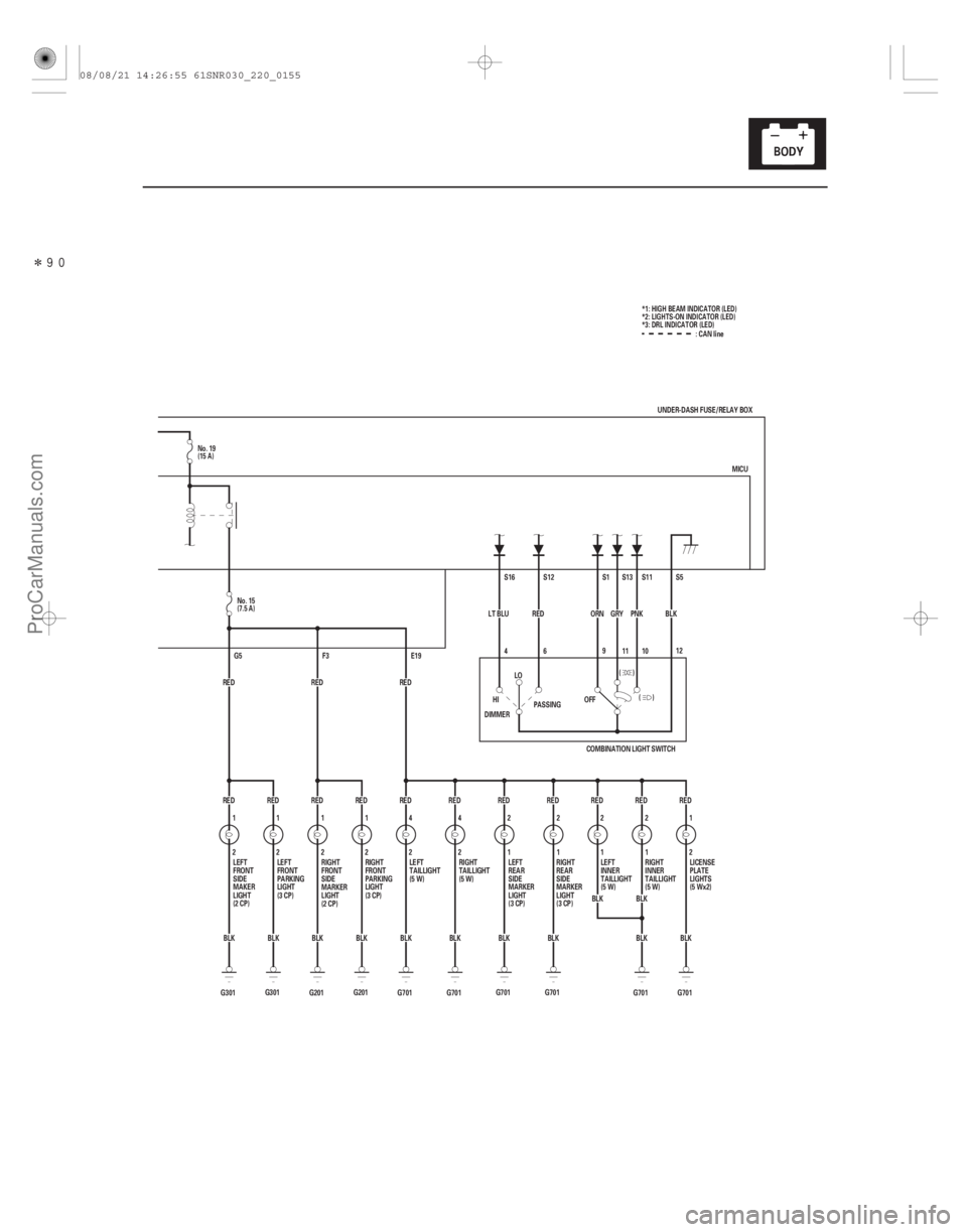
(3 CP) :CANline
UNDER-DASH FUSE/RELAY BOX
1
2 LEFT
FRONT
SIDE
MAKER
LIGHT
(2 CP) LEFT
FRONT
PARKING
LIGHT
(3 CP)
*1: HIGH BEAM INDICATOR (LED)
*2: LIGHTS-ON INDICATOR (LED)
*3: DRL INDICATOR (LED)
No. 19
(15 A)
No. 15
(7.5 A)
08/08/21 14:26:55 61SNR030_220_0155
ProCarManuals.com
DYNOMITE -2009-
Page 2102 of 2893
����
�(�#�'���������������
�����
�����������������)����
�´
�µ
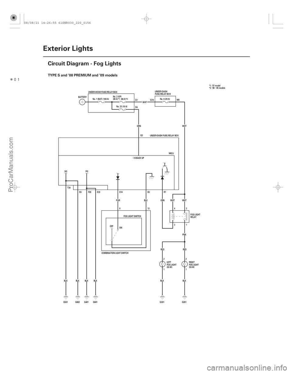
TYPE S and ’08 PREMIUM and ’09 models
22-154Exterior Lights
Circuit Diagram - Fog Lights
E33
BLK
BLK PG
F20
E6
T34
SG
BLK BLK BBACKUP
ORN
No. 23 (10 A)
WHT
No. 6 (20 A)
WHT
1 2
BLK
BLK 2
1
RED
RED PNK
1
3 2
4 WHT
WHT
R7
ORN
BLK
PUR
COMBINATION LIGHT SWITCH 12
8
OFF
BATTERY
No. 1 (BAT) (100 A)
UNDER-HOOD FUSE/RELAY BOX
MICU
UNDER-DASH FUSE/RELAY BOX
S5
S14
FOG LIGHT SWITCH
LEFT
FOG LIGHT
(55 W)RIGHT
FOG LIGHT
(55 W)
UNDER-DASH
FUSE/RELAY BOX
FOG LIGHT
RELAY
G1
D4
G19
M9
G2
G601
G401
G602
G501 G201
G301
ON
No. 2 (OP)
(80 A)*1 (60 A)*2
*1: ’07 model
*2: ’08 09 models
08/08/21 14:26:55 61SNR030_220_0156
ProCarManuals.com
DYNOMITE -2009-
Page 2103 of 2893
���
�(�#�'���������������
�
���������������������)����
22-155
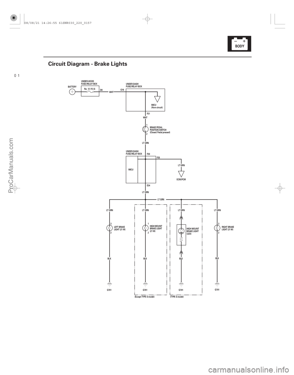
Circuit Diagram - Brake Lights
G16 F31
2 1
LT GRN
LT GRN
LT GRN E34 F30
MICU
2 3 2
1
G701 BLK
BLK
G701
ECM/PCM
LT GRN
LT GRN LT GRN WHT
G701 BLK
WHT
No. 12 (15 A)
BATTERY UNDER-HOOD
FUSE/RELAY BOX
MICU
(Horn circuit)
BRAKE PEDAL
POSITION SWITCH
(Closed: Pedal pressed)
LEFT BRAKE
LIGHT (21 W) HIGH MOUNT
BRAKE LIGHT
(21 W)
UNDER-DASH
FUSE/RELAY BOX
UNDER-DASH
FUSE/RELAY BOX
D8
F25
2 3
LT GRN
BLK
G701
LT GRN
HIGH MOUNT
BRAKE LIGHT
(LED)
(TYPE S model)
(Except TYPE S model) RIGHT BRAKE
LIGHT (21 W)
08/08/21 14:26:55 61SNR030_220_0157
ProCarManuals.com
DYNOMITE -2009-
Page 2104 of 2893
����
�(�#�'���������������
�
���
�����������������)����
�µ
22-156Exterior Lights
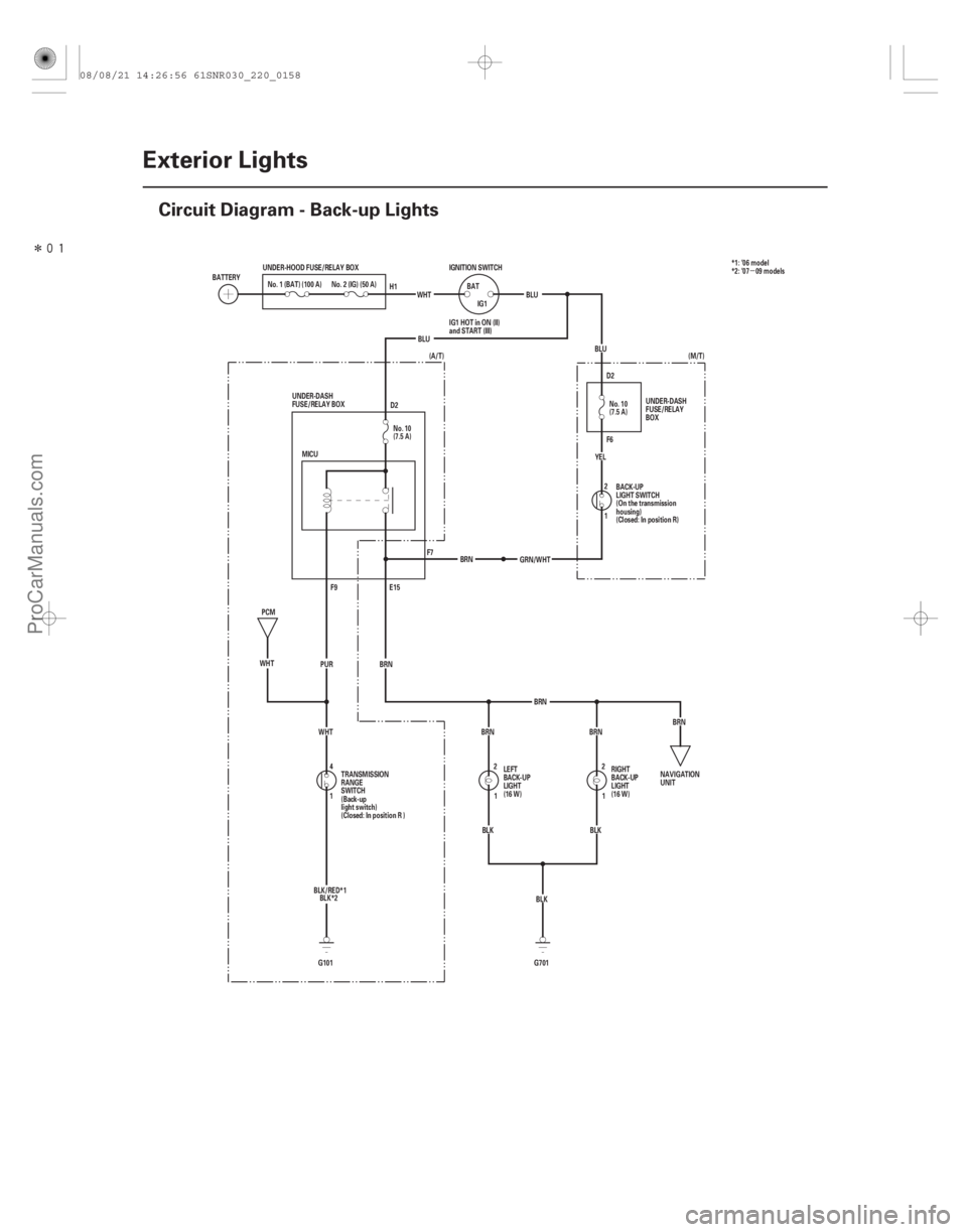
Circuit Diagram - Back-up Lights
F6 D2
D2
BRN
BRN BRN
1 4 BRN
E15
F9
MICU
BLU
BLU
(A/T)
BLK (M/T)
WHT PUR
WHT
G101 G701BLK
BLK
GRN/WHT
1 2
YEL
BLU
IG1
BAT
IGNITION SWITCH
WHT
UNDER-HOOD FUSE/RELAY BOX
No. 2 (IG) (50 A)
No. 1 (BAT) (100 A)
BATTERY
IG1 HOT in ON (II)
and START (III)
UNDER-DASH
FUSE/RELAY
BOX
BACK-UP
LIGHT SWITCH
(On the transmission
housing)
(Closed: In position R)
PCM
TRANSMISSION
RANGE
SWITCH
(Back-up
light switch)
(Closed: In position R ) LEFT
BACK-UP
LIGHT
(16 W)
RIGHT
BACK-UP
LIGHT
(16 W)
UNDER-DASH
FUSE/RELAY BOX
NAVIGATION
UNIT
H1
F7BRN
BRN1
2
1
2No. 10
(7.5 A) No. 10
(7.5 A)*1: ’06 model
*2: ’07 09 models
BLK/RED*1 BLK*2
08/08/21 14:26:56 61SNR030_220_0158
ProCarManuals.com
DYNOMITE -2009-
Page 2105 of 2893
����
�µ
�µ
�µ
�µ �µ
�µ
DTC B1078:
YES
NO
YES
NO YES
NO
22-157
DTC Troubleshooting
UNDER-DASH FUSE/RELAY BOX CONNECTOR E (42P)
GND (BLK)
UNDER-D")
���
�(�#�'��������� �������������.�
�������������)����
�µ
�µ
�µ
�µ �µ
�µ
DTC B1078:
YES
NO
YES
NO YES
NO
22-157
DTC Troubleshooting
UNDER-DASH FUSE/RELAY BOX CONNECTOR E (42P)
GND (BLK)
UNDER-DASH FUSE/RELAY BOX CONNECTOR F (34P) GND (BLK)
GND (BLK)
Daytime Running Lights System
Error
NOTE: If you are troubleshooting multiple DTCs, be
sure to follow the instructions in B-CAN System
Diagnosis Test Mode A (see page 22-93).
1. Turn the ignition switch to ON (II).
2. Pull the parking brake lever.
3. Clear the DTCs with the HDS.
4. Release the parking brake lever.
5. Turn the ignition switch to LOCK (0), and then back to ON (II).
6. Check for DTCs with the HDS.
Go to step 7.
Intermittent failure. The daytime running
lights system is OK at this time. Check for loose or
poor connections.
7. Turn the headlight switch ON (high beam).
Go to step 8.
Go to step 10.
8. Turn the ignition switch to LOCK (0). 9. Measure the voltage between under-dash fuse/
relay box connector E (42P) terminals No. 6 and
No. 33 and body ground, and between under-dash
fuse/relay box connector F (34P) terminal No. 20
and body ground individually.
Faulty MICU; replace the under-dash fuse/
relay box (see page 22-66).
Repair an open in the BLK wire or poor
ground (G 401, G501, G601, G602).
10. Turn the ignition switch to LOCK (0) and turn the headlight switch OFF.
(cont’d)
Wire side of female terminalsWire side of female terminals
Is DTC B1078 indicated?
Do bot h head l i ght s ( hi gh beam) come on? I s t her e l ess t han 0.5 V ?
08/08/21 14:26:56 61SNR030_220_0159
ProCarManuals.com
DYNOMITE -2009-
Page 2106 of 2893

UNDER-DASH FUSE/RELAY BOX CONNECTOR F (34P")
��������
����
�´
�´ �´
�´
�µ
�µ
�µ
�µ
�µ
�µ �µ
�µ
�µ
�µ
YES
NO
YES
NO
YES
NO
YES
NO
YES
NO
22-158Exterior Lights
DTC Troubleshooting (cont’d)
UNDER-DASH FUSE/RELAY BOX CONNECTOR F (34P)
BRH/L(HI)(WHT)
RIGHT HEADLIGHT (HIGH BEAM) 2P CONNECTOR B R H/L (HI) (WHT) UNDER-DASH FUSE/RELAY BOX CONNECTOR G (21P)
LEFT HEADLIGHT (HIGH BEAM) 2P CONNECTOR B L H/L (HI) (PNK)
B L H/L (HI) (PNK)
HEADLIGHT (HIGH BEAM) 2P CONNECTOR GND (BLK)
11. Check the No. 12, No. 13, and No. 18 fuses in theunder-dash fuse/relay box.
Go to step 12.
Replace the blown fuse and recheck. If the
No. 18 (20 A) fuse is blown again, replace the
under-dash fuse/relay box. If the No. 12 (10 A) or
No. 13 (10 A) fuse is blown again, repair a short in
the wire between the under-dash fuse/relay box
and appropriate headlight (high beam).
12. Check the headlight bulbs.
Go to step 13.
Replace the faulty bulb.
13. Disconnect under-dash fuse/relay box connectors F (34P) and G (21P).
14. Disconnect the both headlight (high beam) 2P connectors.
15. Check for continuity between right headlight (high beam) 2P connector terminal No. 2 and under-dash
fuse/relay box connector F (34P) terminal No. 22.
Go to step 16.
Repair an open in the wire between the right
headlight (high beam) and the under-dash fuse/
relay box. 16. Check for continuity between left headlight (high
beam) 2P connector terminal No. 2 and under-dash
fuse/relay box connector G (21P) terminal No. 15.
Go to step 17.
Repair an open in the wire between the left
headlight (high beam) and the under-dash fuse/
relay box.
17. Check for continuity between headlight (high beam) 2P connector terminal No. 1 and body
ground.
Faulty MICU; replace the under-dash fuse/
relay box (see page 22-66).
Repair an open in the BLK wire or poor
ground (G 201-right side, G301-left side).
Wire side of female terminals
Wire side of female terminals Wire side of female terminals
Wire side of female terminals
Wire side of female terminals
Ar e al l f uses OK ? Ar e t he head l i ght bul bs OK ?
Is there continuity? Is there continuity?
Is there continuity?
08/08/21 14:26:57 61SNR030_220_0160
ProCarManuals.com
DYNOMITE -2009-
Page 2107 of 2893
����
�µ
�µ �µ
�µ
�µ
�µ
DTC B1275:
DTC B1276:
DTC B1278:
YES
NO
When the combination light switch is turned OFF
When the combination light switch is")
�(�#�'��������� �������������.�
�������������)����
�µ
�µ �µ
�µ
�µ
�µ
DTC B1275:
DTC B1276:
DTC B1278:
YES
NO
When the combination light switch is turned OFF
When the combination light switch is turned to
PARKING (SMALL) When the combination light switch is turned ON
(HEADLIGHT)
YES
NO
When the combination light switch is turned OFF
YES
NO
22-159
Combination Light Switch OFF
Position Circuit Malfunction
Combination Light Switch
Parking (SMALL) Position Circuit Malfunction
Combination Light Switch ON
Position Circuit Malfunction
NOTE: If you are troubleshooting multiple DTCs, be
sure to follow the instructions in B-CAN System
Diagnosis Test Mode A (see page 22-93).
1. Clear the DTCs with the HDS.
2. Turn the ignition switch to LOCK (0) and then back to ON (II).
3. Turn the combination light switch to the PARKING (SMALL), and ON (low beam) positions for 6
seconds in each position, and then to the OFF
position.
4. Check for DTCs with the HDS.
Go to step 5.
Intermittent failure, the system is OK at this
time. Check for loose or poor connections.
5. Select LIGHTING from the BODY ELECTRICAL system select menu, and enter DATA LIST.
6. Check each combination light switch position value with the DATA LIST menu.
Data List Value
Headlight Switch (OFF) ON
Headlight Switch (PARKING) OFF
Headlight Switch (HEADLIGHT) OFF
Data List Value
Headlight Switch (OFF) OFF
Headlight Switch (PARKING) ON
Headlight Switch (HEADLIGHT) OFF Data List Value
Headlight Switch (OFF) OFF
Headlight Switch (PARKING) ON
Headlight Switch (HEADLIGHT) ON
Faulty MICU; replace the under-dash fuse/
relay box (see page 22-66).
Go to step 7.
7. Turn the ignition switch to LOCK (0).
8. Disconnect the combination light switch 12P connector.
9. Turn the ignition switch to ON (II).
10. Select LIGHTING from the BODY ELECTRICAL system select menu, and enter DATA LIST.
11. Check each combination light switch position value with the DATA LIST menu.
Data List Value
Headlight Switch (OFF) OFF
Headlight Switch (PARKING) OFF
Headlight Switch (HEADLIGHT) OFF
Go to step 15.
Go to step 12.
(cont’d)
I s DT C B12 7 5 , B12 7 6, or B12 7 8 i nd i cat ed ? Are all data list values correct?
Are all data list values indicated OFF?
08/08/21 14:26:57 61SNR030_220_0161
ProCarManuals.com
DYNOMITE -2009-