Page 2080 of 2893
����
22-132Keyless/Power Door Locks/Security System
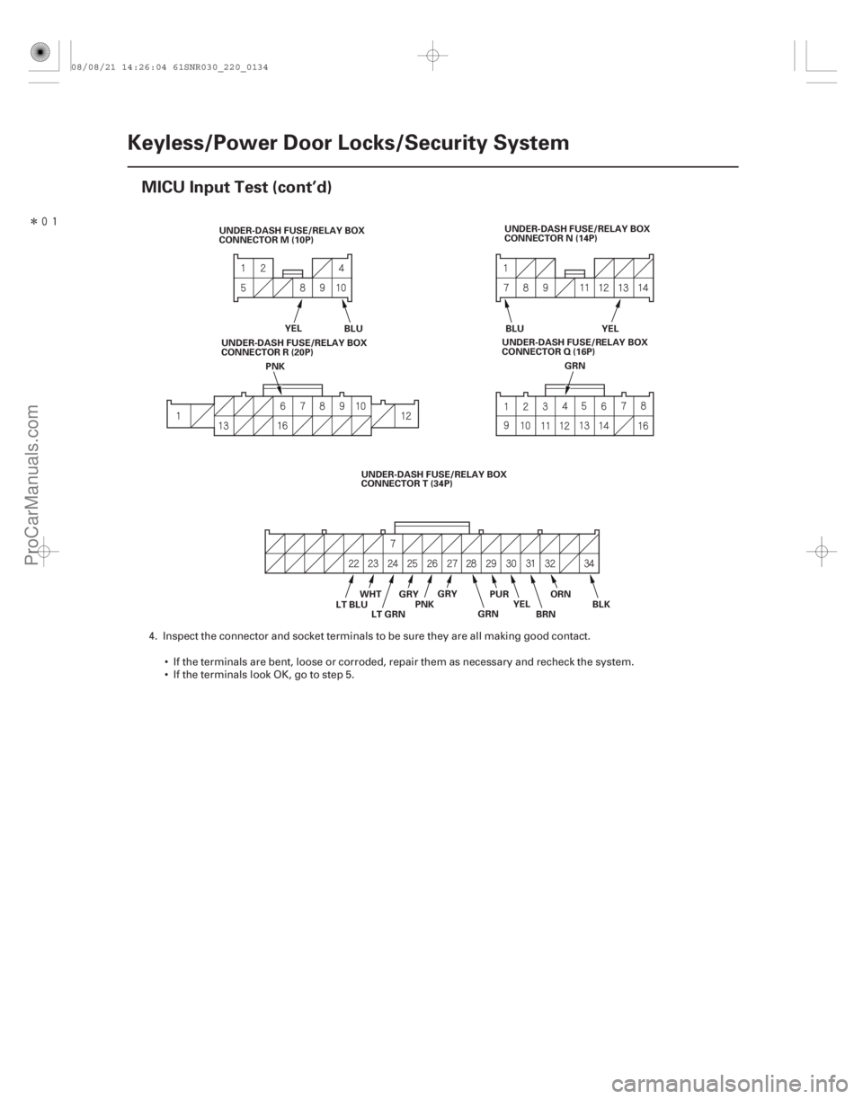
MICU Input Test (cont’d)
YEL
BLU UNDER-DASH FUSE/RELAY BOX
CONNECTOR N (14P)
PNK BLU YEL
UNDER-DASH FUSE/RELAY BOX
CONNECTOR M (10P)
GRN
UNDER-DASH FUSE/RELAY BOX
CONNECTOR T (34P)
LT BLU BLK
ORN
BRN
YEL
PUR
GRN
WHT
LT GRN PNKGRY
GRY
UNDER-DASH FUSE/RELAY BOX
CONNECTORR(20P)
UNDER-DASH FUSE/RELAY BOX
CONNECTOR Q (16P)
4. Inspect the connector and socket terminals to be sure they are all making good contact.
If the terminals are bent, loose or corroded, repair them as necessary and recheck the system.
IftheterminalslookOK,gotostep5.
08/08/21 14:26:04 61SNR030_220_0134
ProCarManuals.com
DYNOMITE -2009-
Page 2081 of 2893

Cavity Wire Test conditionTest: Desired result Possible cause if desired result is
not obtained
22-133
5. With the connector still disconnected, do these input tests at the following connectors.
If any test indicates a problem, find and correct the cause, then recheck the system.
If all the input tests prove OK, go to step 6.
G16 WHT Under all
conditions Measure the voltage to ground:
There should be battery voltage. Blown No. 12 (15 A) fuse in the
under-hood fuse/relay box
An open in the wire
G18 WHT Under all conditions Measure the voltage to ground:
There should be battery voltage. Blown No. 4 (50 A) fuse in the
under-hood fuse/relay box
An open in the wire
G7 LT GRNUnder all
conditions Connect terminals G16 and G7
with a jumper wire
momentarily:
The horn should sound. Poor ground (body ground)
Blown No. 12 (15 A) fuse in the
under-hood fuse/relay box
Faulty horn
An open in the wire
E20 GRN Under all conditions Connect terminals G2 and E20
with a jumper wire:
The trunk release actuator
should work (Trunk lid should
open). Poor ground (G701)
Faulty trunk release actuator
An open in the wire
N7 BLU Under all conditions Connect battery power to
terminal N13 and ground
terminal N7 momentarily:
The driver’s door lock actuator
should unlock. Faulty driver’s door lock
actuator
An open in the wire
N13 YEL
M8 YEL Under all conditions Connect battery power to
terminal M8 and ground
terminal M10 momentarily:
The front passenger’s door lock
actuator should unlock. Faulty front passenger’s door
lock actuator
An open in the wire
M10 BLU
E1 YEL Under all conditions Connect battery power to
terminal E1 and ground
terminal E21 momentarily:
The right rear door lock actuator
should unlock. Faulty right rear door lock
actuator
An open in the wire
E21 BLU
E14 YEL Under all
conditions Connect battery power to
terminal E14 and ground
terminal E31 momentarily:
The left rear door lock actuator
should unlock. Faulty left rear door lock
actuator
An open in the wire
E31 BLU
(cont’d)
08/08/21 14:26:04 61SNR030_220_0135
ProCarManuals.com
DYNOMITE -2009-
Page 2082 of 2893

6. Reconnect the connectors to")
Cavity Wire Test conditionTest: Desired result Possible cause if desired result is
not obtained
22-134Keyless/Power Door Locks/Security System
MICU Input Test (cont’d)
6. Reconnect the connectors to the under-dash fuse/relay box, and do these input tests at the following connectors.
If any test indicates a problem, find and correct the cause, then recheck the system.
If all the input tests prove OK, the MICU must be faulty; replace the under-dash fuse/relay box.
E6 BLK Under all
conditions Measure the voltage to ground:
There should be less than 0.5 V. Poor ground (G602)
An open in the wire
E33 BLK Under all conditions Measure the voltage to ground:
There should be less than 0.5 V. Poor ground (G601)
An open in the wire
F20 BLK Under all conditions Measure the voltage to ground:
There should be less than 0.5 V. Poor ground (G401)
An open in the wire
T34 BLK Under all conditions Measure the voltage to ground:
There should be less than 0.5 V. Poor ground (G501)
An open in the wire
E2 GRY Right rear door open Measure the voltage to ground:
There should be less than 1 V. Faulty right rear door switch
An open in the wire
Right rear door
closed Measure the voltage to ground:
There should be more than 5 V. Faulty right rear door switch
A short to ground in the wire
E3 LT GRNFront passenger’s
door open Measure the voltage to ground:
There should be less than 1 V. Faulty front passenger’s door
switch
An open in the wire
Front passenger’s
door closed Measure the voltage to ground:
There should be more than 5 V. Faulty front passenger’s door
switch
A short to ground in the wire
E17 BRN Left rear door open Measure the voltage to ground: There should be less than 1 V.Faulty left rear door switch
A short to ground in the wire
Left rear door
closed Measure the voltage to ground:
There should be more than 5 V. Faulty left rear door switch
A short to ground in the wire
E36 BLU Trunk lid open Measure the voltage to ground: There should be less than 1 V.Poor ground (G701)
Faulty trunk lid latch switch
An open in the wire
Trunk lid closed Measure the voltage to ground: There should be more than 5 V. Faulty trunk lid latch switch
A short to ground in the wire
E37 GRN Driver’s door open Measure the voltage to ground: There should be less than 1 V.Faulty driver’s door switch
An open in the wire
Driver’s door
closed Measure the voltage to ground:
There should be more than 5 V. Faulty driver’s door switch
A short to ground in the wire
F27 GRN Transmission range switch in P Measure the voltage to ground:
There should be less than 1 V. Poor ground (G101)
Faulty transmission range
switch
An open in the wire
Transmission
range switch in
any other position
than P Measure the voltage to ground:
There should be more than 5 V.
Faulty transmission range
switch
A short to ground in the wire
G13 LT BLUHood open Measure the voltage to ground:
There should be less than 1 V. Poor ground (G401)
Faulty hood switch
An open in the wire
Hood closed Measure the voltage to ground: There should be more than 5 V. Faulty hood switch
A short to ground in the wire
08/08/21 14:26:05 61SNR030_220_0136
ProCarManuals.com
DYNOMITE -2009-
Page 2093 of 2893
����
�(�#�'���������������������������������������)�
��
22-145
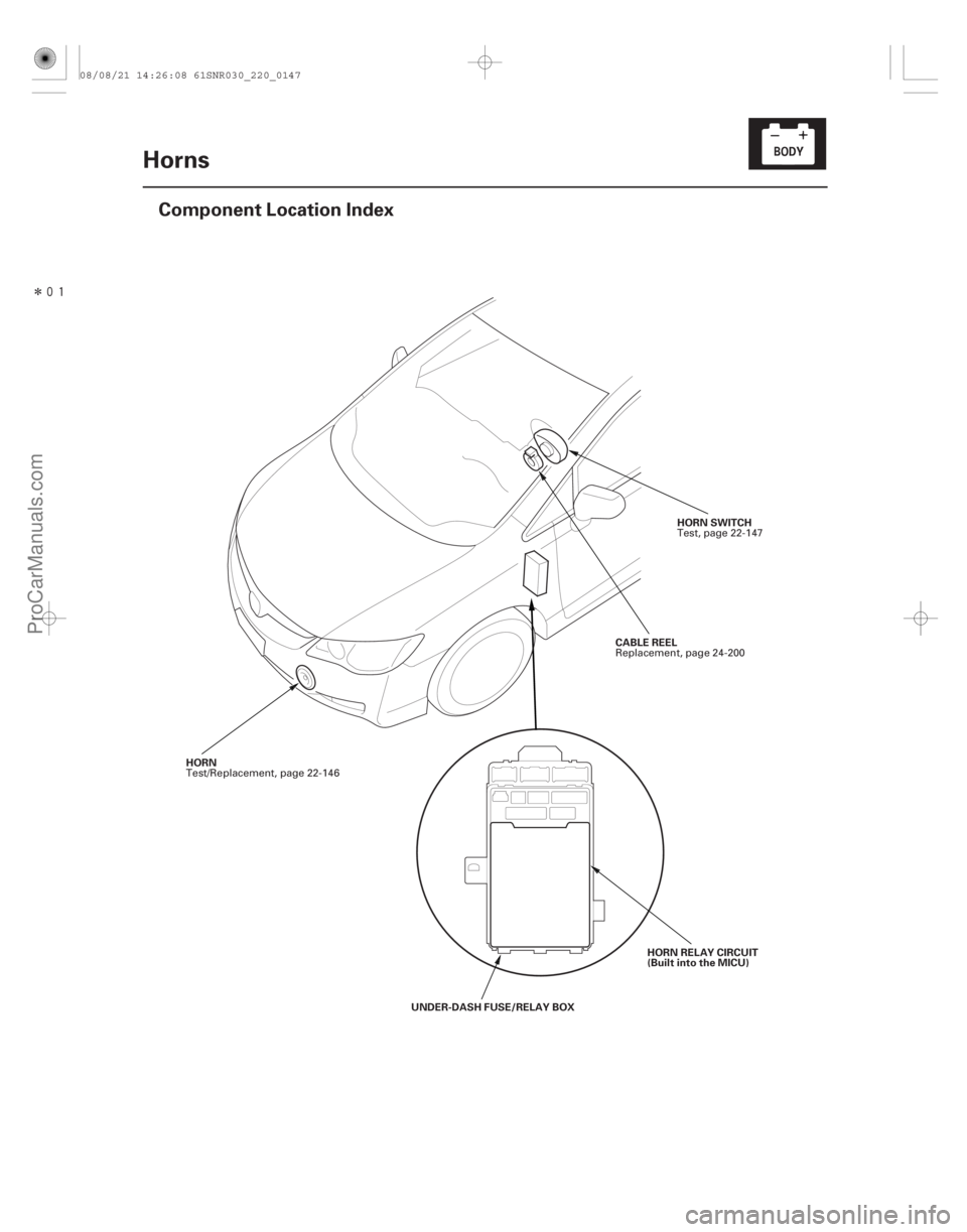
Horns
Component Location Index
HORN SWITCH
CABLE REEL
HORN RELAY CIRCUIT
(Built into the MICU)
HORN
UNDER-DASH FUSE/RELAY BOX Test, page 22-147
Replacement, page 24-200
Test/Replacement, page 22-146
08/08/21 14:26:08 61SNR030_220_0147
ProCarManuals.com
DYNOMITE -2009-
Page 2094 of 2893
����
�(�#�'���������������������������������������)���
���
����
�(�#�'�������������������������������
�������)����
22-14622-146 Horns
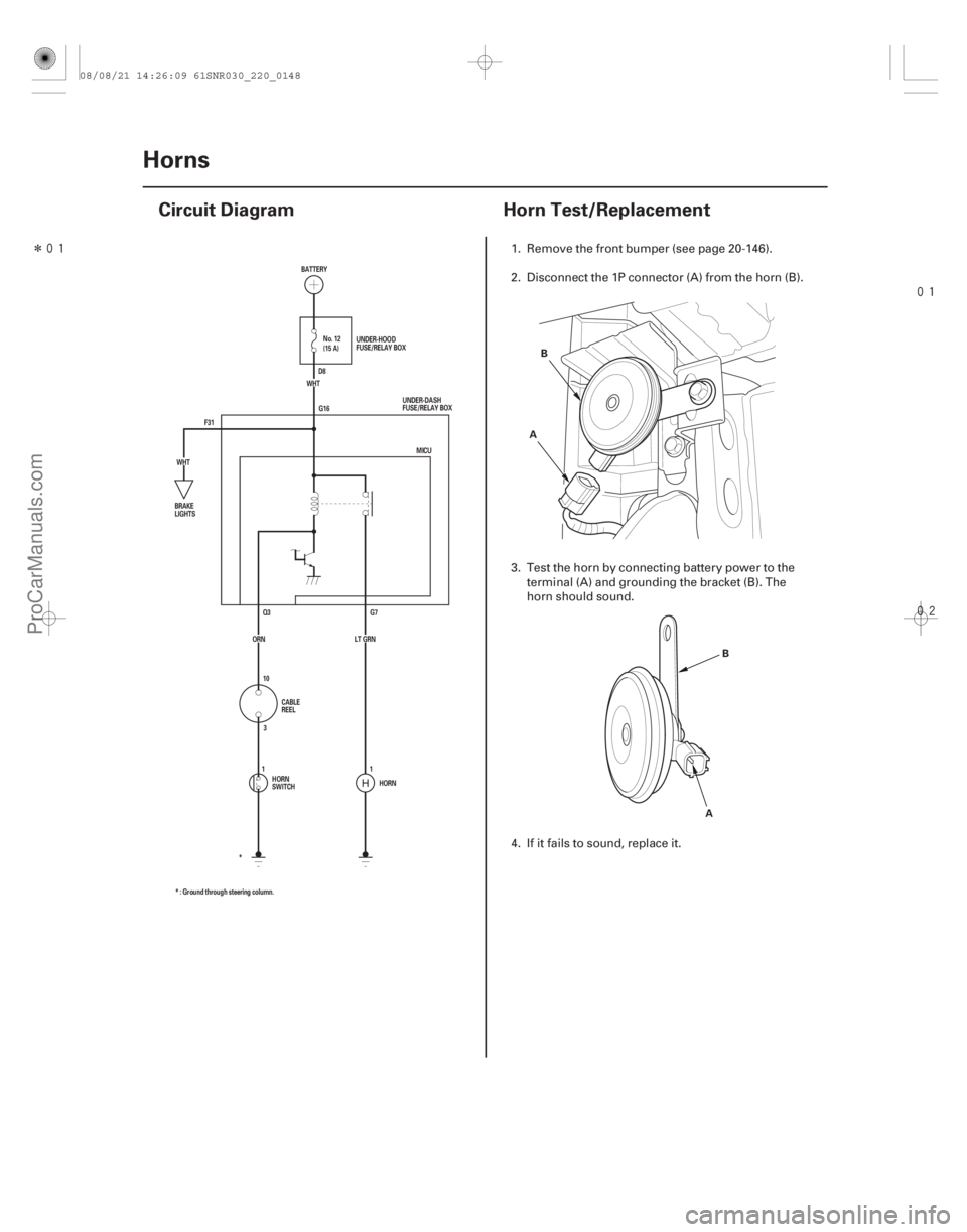
Circuit Diagram
Horn Test/Replacement
F31 G16
G7
Q3
HORN
* : Ground through steering column. * MICU
ORN LT GRN (15 A) No. 12
WHT
WHT BATTERY
UNDER-DASH
FUSE/RELAY BOX
BRAKE
LIGHTS
CABLE
REEL
HORN
SWITCH UNDER-HOOD
FUSE/RELAY BOX
D8
10 3
11A B
AB
1. Remove the front bumper (see page 20-146).
2. Disconnect the 1P connector (A) from the horn (B).
3. Test the horn by connecting battery power to the
terminal (A) and grounding the bracket (B). The
horn should sound.
4. If it fails to sound, replace it.
08/08/21 14:26:09 61SNR030_220_0148
ProCarManuals.com
DYNOMITE -2009-
Page 2095 of 2893
�
��
22-147
Horn Switch Test
A A
B
C
1. Remove the steering column covers (see page
17-9).
2. Disconnect the cable reel 20P connector (A) from")
����
����
�(�#�'�����������������������������
�
�������)�
��
22-147
Horn Switch Test
A A
B
C
1. Remove the steering column covers (see page
17-9).
2. Disconnect the cable reel 20P connector (A) from the dashboard wire harness.
3. Using a jumper wire, connect dashboard wire harness 20P connector terminal No. 10 to body
ground. The horn should sound.
If the horn sounds, go to step 4.
If the horn does not sound, check these items: – No. 12 (15 A) fuse in the under-hood fuse/relay box.
– MICU.
– Horn.
– Anopeninthewire. 4. Reconnect the cable reel 20P connector (A) to the
dashboard wire harness.
5. Remove the driver’s airbag assembly (see page 24-188), and disconnect the horn switch 1P positive
terminal (B) from the cable reel (C).
6. Using a jumper wire, connect the 1P connector to body ground.
If the horn sounds, replace the driver’s airbag assembly.
If the horn does not sound, check these items: – Cable reel.
– Anopeninthewire.
Wire side of
female terminals
08/08/21 14:26:09 61SNR030_220_0149
ProCarManuals.com
DYNOMITE -2009-
Page 2098 of 2893
������(�#�'�����!���������
�����
�����������������)�
��
�´
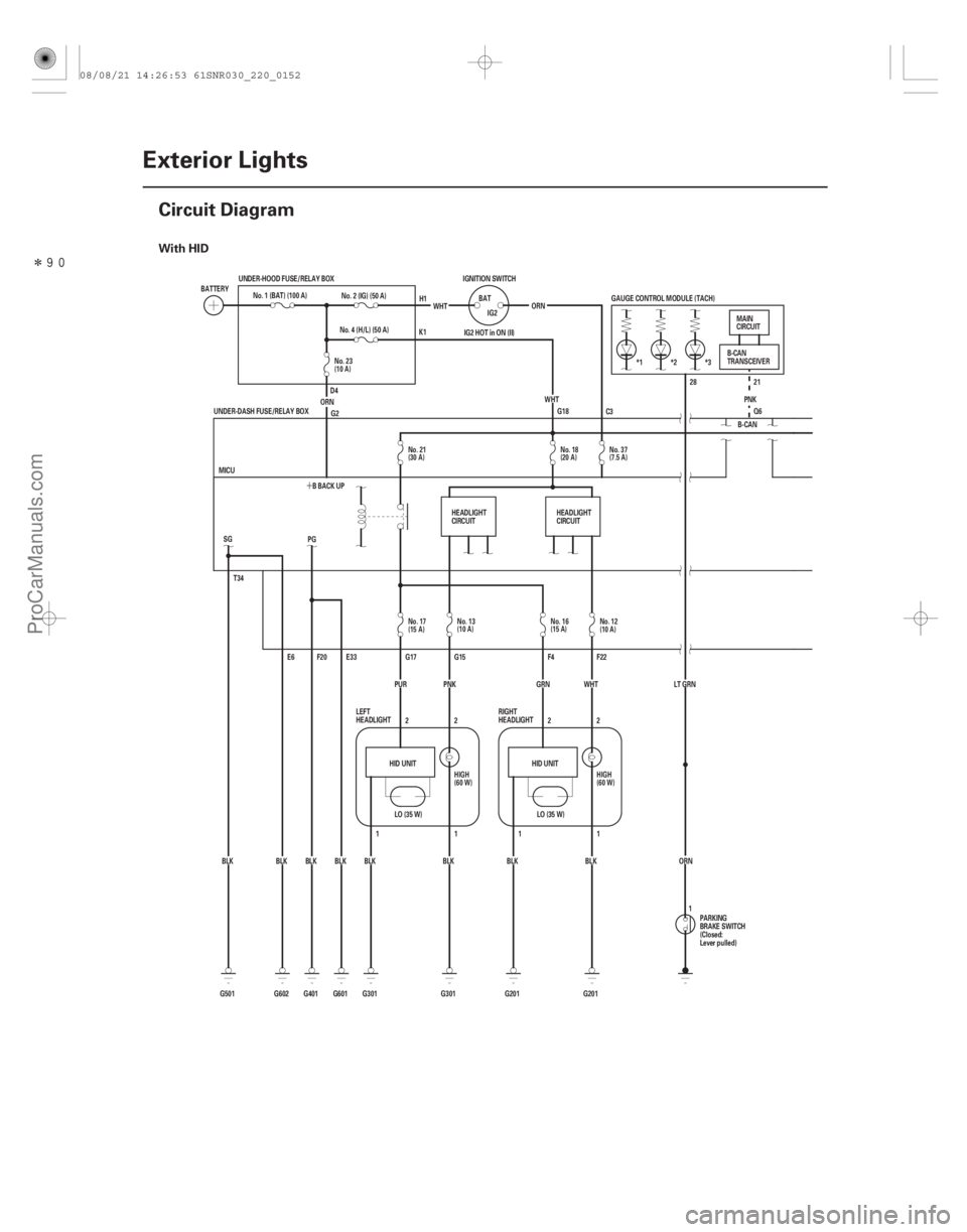
With HID
22-150Exterior Lights
Circuit Diagram
BATTERY
No. 1 (BAT) (100 A)
UNDER-HOOD FUSE/RELAY BOX
No. 4 (H/L) (50 A)
ORN No. 2 (IG) (50 A)
WHT
IGNITION SWITCH
BATIG2
WHT
ORN
IG2 HOT in ON (II)
G18 28 21
Q6
PNK
GAUGE CONTROL MODULE (TACH)
*1 *2 *3
LT GRNORN B-CAN
T34
G501 BLK
LO (35 W)
HID UNIT HID UNIT
LO (35 W)
G2
BLK
BLK
BLK
BLK
BLK BLK SG
E6
G602 G601 E33
F20
PG
BLK
G401 BBACKUP
MICU
G301 G201 F22
F4
G15
G17
2
2
11
1 2
1 2
G201
G301 GRN WHT
PUR
UNDER-DASH FUSE/RELAY BOX
PNK PARKING
BRAKE SWITCH
(Closed:
Lever pulled)B-CAN
TRANSCEIVER
MAIN
CIRCUIT
LEFT
HEADLIGHT RIGHT
HEADLIGHT
H1
K1
D4 C3
1
HEADLIGHT
CIRCUIT
HEADLIGHT
CIRCUIT
No. 37
(7.5 A)
No. 18
(20 A)
No. 21
(30 A)
No. 23
(10 A)
No. 17
(15 A)No. 13
(10 A) No. 16
(15 A)
No. 12
(10 A)
HIGH
(60 W) HIGH
(60 W)
08/08/21 14:26:53 61SNR030_220_0152
ProCarManuals.com
DYNOMITE -2009-
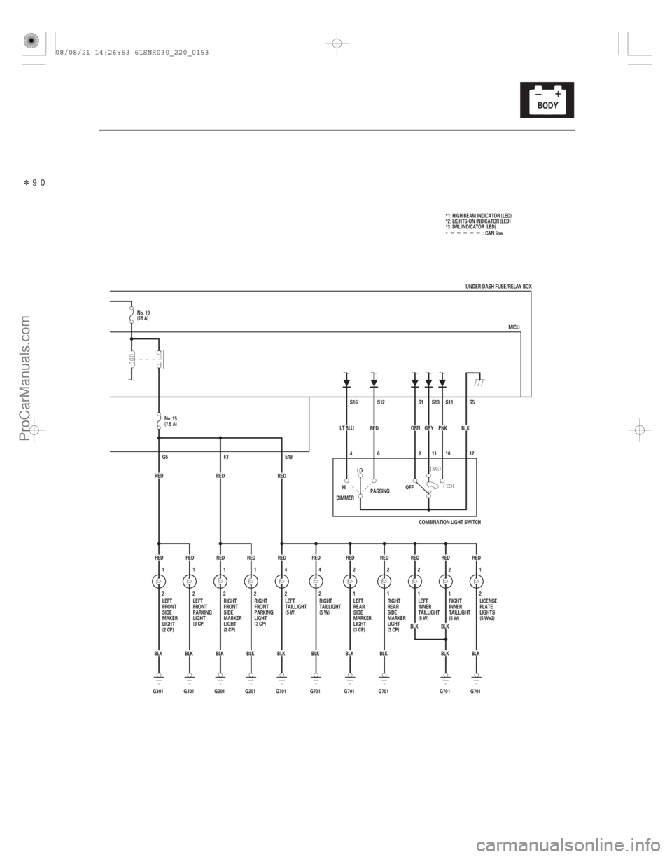
Page 2099 of 2893
�����
22-151
1
BLK
G301 2
RED
RED RED RED
2 1
G201 BLK 1
2
2
4
G701
G701 MICU
9
1
2
RED RED
BLK BLK S1
ORN
BLK BLK BLK
BLK
BLK
BLK
BLK RED
RED
RED
RED S5
S11
S13
S12
S16
BLK
PNK
GRY
RED
LT BLU
G701
E19
RED
F3
RED
G201 RED
G301 BLK
G701
G701 G701
1
2
1
24
2 2
12
1 1
2
RED
G5
12
(
()
1011
6
4
)
OFF
LO
HI
DIMMER PASSING
COMBINATION LIGHT SWITCH :CANline
UNDER-DASH FUSE/RELAY BOX
LEFT
FRONT
SIDE
MAKER
LIGHT
(2 CP) RIGHT
FRONT
SIDE
MARKER
LIGHT
(2 CP) LEFT
TAILLIGHT
(5 W)
RIGHT
TAILLIGHT
(5 W)LEFT
REAR
SIDE
MARKER
LIGHT
(3 CP)RIGHT
REAR
SIDE
MARKER
LIGHT
(3 CP) RIGHT
INNER
TAILLIGHT
(5 W)
LEFT
INNER
TAILLIGHT
(5 W) LICENSE
PLATE
LIGHTS
(5 Wx2)
RIGHT
FRONT
PARKING
LIGHT
(3 CP)
LEFT
FRONT
PARKING
LIGHT
(3 CP)
*1: HIGH BEAM INDICATOR (LED)
*2: LIGHTS-ON INDICATOR (LED)
*3: DRL INDICATOR (LED)
No. 15
(7.5 A)
No. 19
(15 A)
08/08/21 14:26:53 61SNR030_220_0153
ProCarManuals.com
DYNOMITE -2009-