Page 2162 of 2893
�����(�#�'���������������������������������������)����
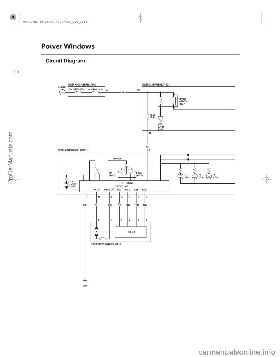
22-212Power Windows
Circuit Diagram
G21
N9
5
2
3
6
4
1
11
(LED) *3
(LED)
*1 *2 (LED)
UNDER-DASH FUSE/RELAY BOX
BLU
No. 4 (P/W) (40 A)
UNDER-HOOD FUSE/RELAY BOX
No. 1 (BAT) (100 A)
BATTERY
CONTROL UNITDOWN
UP
DRIVER’S
YEL GRN PUR
PNKORN
UP DOWN SVCC PLSA PLSB
6
5
16
9
10 4
POWER WINDOW MASTER SWITCH No. 26
(20 A)
WHT
PULSER
BLK
G503 7
SGND
BRN POWER
WINDOW
RELAY
DOWN
(AUTO)
UP
(AUTO) MICU
(Key-off
timer)
DR
LIGHT
(LED) K2
DRIVER’S POWER WINDOW MOTOR 32
4 1
08/08/21 14:28:39 61SNR030_220_0214
ProCarManuals.com
DYNOMITE -2009-
Page 2163 of 2893
����
22-213
PUR
RED
GRN *3 : RIGHT REAR *2 : LEFT REAR *1 : FRONT PASSENGER
2
1 BLU
WHT 8
7 45
(LED) LIGHT
DN
UP
OFF OFF 3 RED
14
13
LT BLU
GRN 22
21
PUR
3 OFF
OFF UP
DN
LIGHT
(LED)
5
4
78
YEL BRN 21
1
2 RED
BLU 8
7 45
(LED) LIGHT
DN
UP
OFF OFF
3 BRN
2
1
ORN LEFT REAR
RIGHT REAR
OFF DN
UP
OFF
UP DN
12
BLK
G503
DN
UP OFF PUR
LT GRN
RED
GRN
15
RED (20 A) No. 32
20
PUR (20 A)
No. 33
3
GRN (20 A)
No. 30 UNDER-DASH FUSE/RELAY BOX
MAIN
SWITCH
FRONT
PASSENGER’S
POWER WINDOW
MASTER SWITCH
N1
M4 N8E41 N14
E23
RED
FRONT
PASSENGER’S
POWER
WINDOW SWITCH LEFT REAR
POWER
WINDOW SWITCHRIGHT REAR
POWER
WINDOW SWITCH
FRONT
PASSENGER’S
POWER
WINDOW
MOTOR LEFT
REAR
POWER
WINDOW
MOTOR
RIGHT
REAR
POWER
WINDOW
MOTOR
08/08/21 14:28:39 61SNR030_220_0215
ProCarManuals.com
DYNOMITE -2009-
Page 2166 of 2893

5. Reconnect")
�µ
�µ�µ
�µ
�µ�µ
Cavity Wire Test condition Test: Desired result Possible cause if desired result is not
obtained
22-216Power Windows
Power Window Master Switch Input Test (cont’d)
5. Reconnect the 22P connector to the power window master switch. Turn the ignition switch to ON (II), and do these input tests at the
following connector.
If any test indicates a problem, find and correct the cause, then recheck the system.
If all the input tests prove OK, the control unit must be faulty; replace the power window master switch.
3 GRN Ignition switch ON (II) Measure the voltage to ground:
There should be battery voltage.Blown No. 30 (20 A) fuse in the under-
dash fuse/relay box
Faulty power window relay
Faulty MICU
An open in the wire
4 WHT Under all conditions Measure the voltage to ground: There should be battery voltage.Blown No. 26 (20 A) fuse in the under-
dash fuse/relay box
An open in the wire
15 RED Ignition switch ON (II) Measure the voltage to ground: There should be battery voltage.Blown No. 32 (20 A) fuse in the under-
dash fuse/relay box
Faulty power window relay
Faulty MICU
An open in the wire
20 PUR Ignition switch ON (II) Measure the voltage to ground: There should be battery voltage.Blown No. 33 (20 A) fuse in the under-
dash fuse/relay box
Faulty power window relay
Faulty MICU
An open in the wire
7 BRN Under all conditions Measure the voltage to ground: There should be less than 0.5 V.Poor ground (G503)
An open in the wire
11 BLK Under all conditions Measure the voltage to ground: There should be less than 0.5 V.Poor ground (G503)
An open in the wire
12 BLK Under all conditions Measure the voltage to ground: There should be less than 0.5 V.Poor ground (G503)
An open in the wire
16 PUR Ignition switch ON (II) Measure the voltage to ground: There should be battery voltage.Faulty power window master switch
A short to ground in the wire
5 PNK Ignition switch ON (II), and driver’s power window switch
moving up or down Measure the voltage between
terminals No. 5 and No. 7:
There should be 0 V about
5 V 0 V about 5 V repeatedly
(a digital voltmeter should read
about 2.5 V while the window
moves). Faulty power window master switch
Faulty driver’s power window motor
An open in the wire
A short to ground in the wire
6 ORN Ignition switch ON (II), and driver’s power window switch
moving up or down Measure the voltage between
terminals No. 6 and No. 7:
There should be 0 V about
5 V 0 V about 5 V repeatedly
(a digital voltmeter should read
about 2.5 V while the window
moves).
6. Reset the power window control unit (see page 22-210).
08/08/21 14:28:40 61SNR030_220_0218
ProCarManuals.com
DYNOMITE -2009-
Page 2171 of 2893
����
�(�#�'���������������������������������������)����
22-221
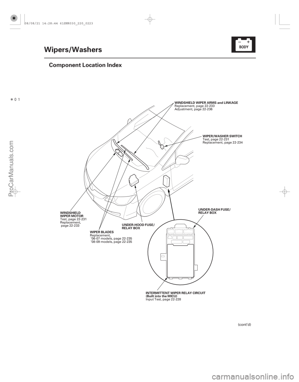
Wipers/Washers
Component Location Index
WIPER/WASHER SWITCH
WINDSHIELD WIPER ARMS and LINKAGE
WIPER BLADES UNDER-HOOD FUSE/
RELAY BOX
WINDSHIELD
WIPER MOTOR
UNDER-DASH FUSE/
RELAY BOX
INTERMITTENT WIPER RELAY CIRCUIT
(Built into the MICU)
(cont’d)
Test, page 22-231
Replacement, page 22-234
Replacement, page 22-233
Adjustment, page 22-236
Replacement, ’06-07 models, page 22-235
’08-09 models, page 22-235
Test, page 22-231
Replacement,
page 22-233
Input Test, page 22-228
08/08/21 14:28:44 61SNR030_220_0223
ProCarManuals.com
DYNOMITE -2009-
Page 2173 of 2893
����
�(�#�'���������������������������������������)����
22-223
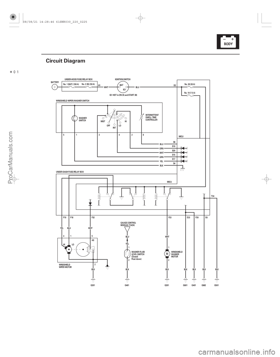
Circuit Diagram
D2
BLK
G401 F20
G601 BLK E33
HI LO BLK
G201 AS
2 E6
BLK
G602
IG1 HOT in ON (II) and START (III)
BLU
G401 BLK YEL
2 1 T34
G501BLK
UNDER-DASH FUSE/RELAY BOX
MICU
F33
F32
F19 F18 8
2
4
3
1
5
5
41 WHT
YEL BLU
WINDSHIELD WIPER/WASHER SWITCH
MICU
S4
S17 S15
S20 S10 S6
ORN
WHT GRN
YEL
BLU No. 10 (7.5 A)
No. 38 (30 A)
WHT
BLK
HI
LO
MIST
INT
OFF
BATTERY
No. 2 (IG) (50 A)
UNDER-HOOD FUSE/RELAY BOX
WHTIGNITION SWITCH
BATIG1 BLU
BLK
G201 1
2
No. 1 (BAT) (100 A)
WASHER
SWITCH INTERMITTENT
DWELL TIME
CONTROLLER
WINDSHIELD
WASHER
MOTOR
WASHER FLUID
LEVEL SWITCH
(Closed:
Float down)
GAUGE CONTROL
MODULE (TACH)
WINDSHIELD
WIPER MOTOR H1
08/08/21 14:28:46 61SNR030_220_0225
ProCarManuals.com
DYNOMITE -2009-
Page 2174 of 2893
����
�µ
�µ
�µ
�µ
�µ
�µ �µ
�µ
�µ
�µ
DTC B1077:
YES
NO
YES
NO
YES
NO YES
NO
YES
NO
22-224Wipers/Washers
DTC Troubleshooting
UNDER-DASH F")
���
����
�(�#�'��������� �������������.�
�������������)����
�µ
�µ
�µ
�µ
�µ
�µ �µ
�µ
�µ
�µ
DTC B1077:
YES
NO
YES
NO
YES
NO YES
NO
YES
NO
22-224Wipers/Washers
DTC Troubleshooting
UNDER-DASH FUSE/RELAY BOX CONNECTOR F (34P)
WINDSHIELD WIPER MOTOR 5P CONNECTOR AS (WHT)
AS (WHT)
WINDSHIELD WIPER MOTOR 5P CONNECTOR AS (WHT)
Windshield Wiper (As) Signal
Error
NOTE: If you are troubleshooting multiple DTCs, be
sure to follow the instructions in B-CAN System
Diagnosis Test Mode A (see page 22-93).
1. Clear the DTCs with the HDS.
2. Turn the ignition switch to LOCK (0), and then back to ON (II).
3. Turn the wiper switch to LOW or HIGH for 15 seconds or more, then turn the switch OFF.
Go to step 4.
Go to step 12.
4. Check for DTCs with the HDS.
Go to step 5.
Intermittent failure. The windshield wiper
system is OK at this time. Check for loose or poor
connections.
5. Turn the ignition switch to LOCK (0).
6. Do the wiper motor test (see page 22-231).
Go to step 7.
Replace the windshield wiper motor
(see page 22-233) and recheck.
7. Disconnect under-dash fuse/relay box connector F (34P) and windshield wiper motor 5P connector. 8. Check for continuity between windshield wiper
motor 5P connector terminal No. 5 and under-dash
fuse/relay box connector F (34P) terminal No. 32.
Go to step 9.
Repair an open in the WHT wire.
9. Check for continuity between windshield wiper motor 5P connector terminal No. 5 and body
ground.
Repair a short in the WHT wire.
Go to step 10.
Wire side of female terminals
Wire side of female terminals
Wire side of female terminals
Do t he w i nd shi el d w i per r un? Is DTC B1077 indicated?
Does t he w i per mot or r un nor mal l y and d oes i tpul se? Is there continuity?
Is there continuity?
08/08/21 14:28:46 61SNR030_220_0226
ProCarManuals.com
DYNOMITE -2009-
Page 2175 of 2893
 UNDER-DASH FUSE/RELAY BOX CONNECTOR F (34P)
LOW (BLU) HI")
��������
����
�µ
�µ
�µ
�µ
�µ
�µ �µ
�µ
�µ
�µ
YES
NO
YES
NO
YES
NO
YES
NO
YES
NO
22-225
WINDSHIELD WIPER MOTOR 5P CONNECTOR
AS (WHT) UNDER-DASH FUSE/RELAY BOX CONNECTOR F (34P)
LOW (BLU) HIGH (YEL)
WINDSHIELD WIPER MOTOR 5P CONNECTOR GND (BLK)
10. Turn the ignition switch to ON (II).
11. Measure the voltage between windshield wipermotor 5P connector terminal No. 5 and body
ground.
Repair a short to power in the WHT wire.
Faulty MICU; replace the under-dash fuse/
relay box.
12. Turn the ignition switch to LOCK (0).
13. Check the No. 38 (30 A) fuse in the under-dash fuse/ relay box.
Go to step 14.
Replace the fuse and recheck the system.
14. Do the wiper motor test (see page 22-231).
Go to step 15.
Replace the windshield wiper motor
(see page 22-233) and recheck.
15. Reconnect the windshield wiper motor 5P connector. 16. Measure the voltage between under-dash fuse/
relay box connector F (34P) terminals No. 18 (LOW)
and No. 19 (HIGH) and body ground with the wiper
switch in corresponding position.
Go to step 17.
Faulty MICU; replace the under-dash fuse/
relay box (see page 22-66).
17. Measure the voltage between windshield wiper motor 5P connector terminal No. 2 and body
ground.
Repair an open in the BLU (LOW) or YEL
(HIGH) wire.
Repair an open in the BLK wire or poor
ground (G 201).
Wire side of female terminals Wire side of female terminals
Wire side of female terminals
Is there voltage? IsthefuseOK?Does t he w i per mot or r un nor mal l y ? Is there battery voltage?
Is t her e l ess t han 0.5 V ?
08/08/21 14:28:46 61SNR030_220_0227
ProCarManuals.com
DYNOMITE -2009-
Page 2176 of 2893
�
��
�µ
�µ
�µ
�µ �µ
�µ
�µ
�µ
DTC B1281:
DTC B1282:
DTC B1283:
DTC B1284:
YES
NO
When the wiper switch is turned OFF Data List Value
YES
NO From te")
�(�#�'��������� �������������.�
�����
�������)�
��
�µ
�µ
�µ
�µ �µ
�µ
�µ
�µ
DTC B1281:
DTC B1282:
DTC B1283:
DTC B1284:
YES
NO
When the wiper switch is turned OFF Data List Value
YES
NO From terminal To terminal
YES
NO
When the wiper switch is turned OFF Data List Value
YES
NO
22-226 Wipers/Washers
DTC Troubleshooting (cont’d)
Windshield Wiper Switch MIST
Position Circuit Malfunction
Windshield Wiper Switch INT
Position Circuit Malfunction
Windshield Wiper Switch LOW
Position Circuit Malfunction
Windshield Wiper Switch HIGH
Position Circuit Malfunction
NOTE: If you are troubleshooting multiple DTCs, be
sure to follow the instructions in B-CAN System
Diagnosis Test Mode A (see page 22-93).
1. Clear the DTCs with the HDS.
2. Turn the ignition switch to LOCK (0) and then back to ON (II).
3. Turn the wiper switch to the MIST, INT, LOW, HIGH, and OFF positions, and wait for at least 6 seconds.
4. Check for DTCs with the HDS.
Go to step 5.
Intermittent failure, the wiper system is OK at
this time. Check for loose or poor connections.
5. Select WIPERS from the BODY ELECTRICAL menu, and enter DATA LIST.
6. Check each wiper switch position value with the DATA LIST menu.
Wiper switch (LOW) OFF
Wiper switch (HIGH) OFF
Wiper switch (MIST) OFF
Wiper switch (INT) OFF Go to step 7.
Go to step 10. 7. Turn the ignition switch to LOCK (0).
8. Disconnect under-dash fuse/relay box connector S
(20P).
9. Check for continuity between under-dash fuse/relay box connector S (20P) terminals as shown:
10 6, 15, 20
15 6, 20
Repair a short between the wires.
Faulty MICU; replace the under-dash fuse/
relay box (see page 22-66).
10. Turn the ignition switch to LOCK (0).
11. Disconnect the 8P connector from the wiper switch.
12. Turn the ignition switch to ON (II).
13. Check each wiper switch position value with the DATA LIST menu.
Wiper switch (LOW) OFF
Wiper switch (HIGH) OFF
Wiper switch (MIST) OFF
Wiper switch (INT) OFF Replace the wiper/washer switch (see page
22-234).
Go to step 14.
I s DT C B12 81, B12 82 , B12 83, or B12 84 i nd i cat ed ?
Are all data list values correct? Is there continuity?
Are all data list values correct?
08/08/21 14:28:47 61SNR030_220_0228
ProCarManuals.com
DYNOMITE -2009-