Page 2203 of 2893
����
22-253
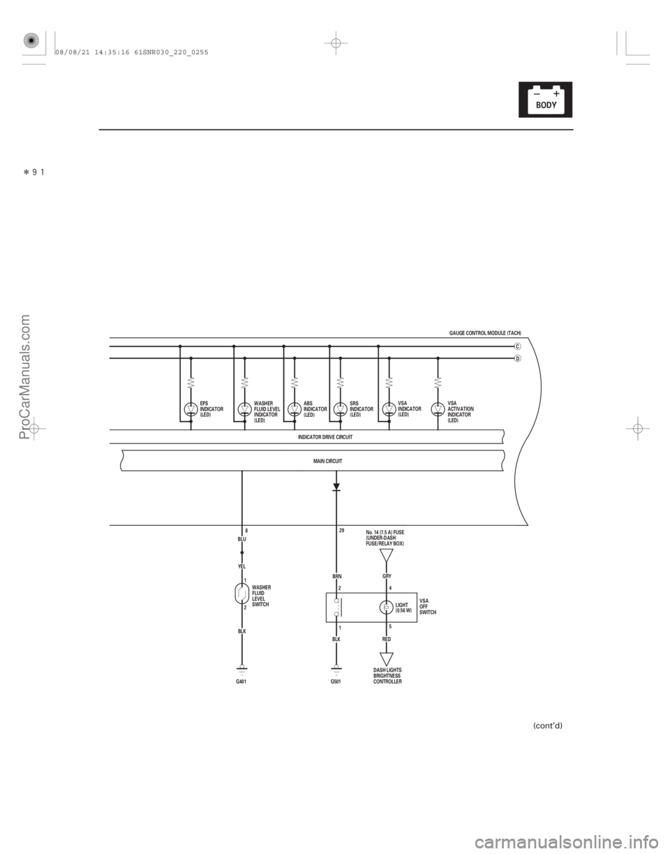
BLUYEL
BLK
G401 2 1
8 MAIN CIRCUIT
INDICATOR DRIVE CIRCUIT D
EPS
INDICATOR
(LED) VSA
INDICATOR
(LED)
SRS
INDICATOR
(LED)
ABS
INDICATOR
(LED)
WASHER
FLUID LEVEL
INDICATOR
(LED)
WASHER
FLUID
LEVEL
SWITCH VSA
ACTIVATION
INDICATOR
(LED)
5
2
4
1 No. 14 (7.5 A) FUSE
REDGRY
(0.56 W) LIGHT
BRN
BLK (UNDER-DASH
FUSE/RELAY BOX)
VSA
OFF
SWITCH
DASH LIGHTS
BRIGHTNESS
CONTROLLER
G501 29 GAUGE CONTROL MODULE (TACH)
C
(cont’d)
08/08/21 14:35:16 61SNR030_220_0255
ProCarManuals.com
DYNOMITE -2009-
Page 2204 of 2893
�����
�µ�´�µ
22-254Gauges
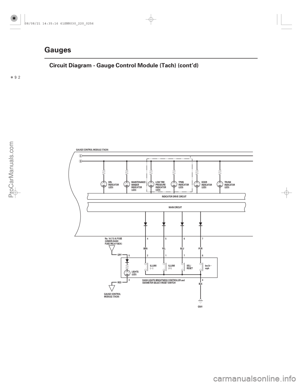
Circuit Diagram - Gauge Control Module (Tach) (cont’d)
GAUGE CONTROL MODULE (TACH)
D
MAIN CIRCUIT
INDICATOR DRIVE CIRCUIT
DRL
INDICATOR
(LED)
DOOR
INDICATOR
(LED)TRUNK
INDICATOR
(LED)
MAINTENANCE
MINDER
INDICATOR
(LED) *
LOW TIRE
PRESSURE
INDICATOR
(LED) TPMS
INDICATOR
(LED)
G5014
3 6
7
1
2
5
BLK
PUR
7
BLU 6
YEL 5
4
BRN
GRY
RED ILLUMI
()
ILLUMI
()SEL/
RESETkm/h
mph
LIGHTS
(LED)
GAUGE CONTROL
MODULE (TACH) No. 14 (7.5 A) FUSE
(UNDER-DASH
FUSE/RELAY BOX)
DASH LIGHTS BRIGHTNESS CONTROLLER and
ODOMETER SELECT/RESET SWITCH
C
08/08/21 14:35:16 61SNR030_220_0256
ProCarManuals.com
DYNOMITE -2009-
Page 2206 of 2893
����
�µ
�´
�µ
22-256 Gauges
Circuit Diagram - Dash Lights Brightness Controller
RED
GRY
BRN45
YEL 6
BLU 7
PUR
BLK
2176
4
G501 13
RED
14
16
BLK B")
����
�(�#�'���������������������
�����������������)����
�µ
�´
�µ
22-256 Gauges
Circuit Diagram - Dash Lights Brightness Controller
RED
GRY
BRN45
YEL 6
BLU 7
PUR
BLK
2176
4
G501 13
RED
14
16
BLK BLK
G503
13
RED
16
BLK BLK
G504 15
MAIN CIRCUIT
WHT BRN
No. 2 (IG) (50 A)
GAUGE CONTROL MODULE (TACH) 18 17
ORN
IG1
BAT
BLU
WHT
No. 23 (10 A)
BATTERY
IGNITION SWITCH
No. 1 (BAT) (100 A)
(7.5 A) No. 10
UNDER-DASH
FUSE/RELAY
BOX IG1 HOT in ON (II)
and START (III)
DASH LIGHTS BRIGHTNESS CONTROLLER and
ODOMETER SELECT/RESET SWITCH
No. 14 (7.5 A) FUSE
(UNDER-DASH
FUSE/RELAY BOX)
GAUGE CONTROL
MODULE (TACH) km/h
mph
SEL/
RESET
ILLUMI
()
ILLUMI
()
H1
D4 G2D2
UNDER-HOOD FUSE/RELAY BOX
5
3LIGHTS
(LED) Q1 Q9
MICU A/T GEAR POSITION INDICATOR
PANEL LIGHT
AMBIENT LIGHT
SEAT HEATER SWITCHES LIGHT
DRIVER’S FOOTWELL LIGHT*1
FRONT PASSENGER’S
FOOTWELL LIGHT*1
CLIMATE CONTROL UNIT*2
DASH LIGHTS BRIGHTNESS
CONTROLLER*2
FRONT PASSENGER’S
AIRBAG CUTOFF INDICATOR*2
VSA OFF SWITCH*2
AUDIO UNIT
NAVIGATION UNIT
HAZARD WARNING SWITCH LIGHT
MOONROOF SWITCH LIGHT
STEERING SWITCHES LIGHT
CLIMATE CONTROL UNIT*1
DASH LIGHTS BRIGHTNESS
CONTROLLER*1
FRONT PASSENGER’S
AIRBAG CUTOFF INDICATOR*1
VSA OFF SWITCH*1
*1: TYPE S model
*2: Except TYPE S model
08/08/21 14:35:17 61SNR030_220_0258
ProCarManuals.com
DYNOMITE -2009-
Page 2208 of 2893
������(�#�'���������������
�����������������������)���
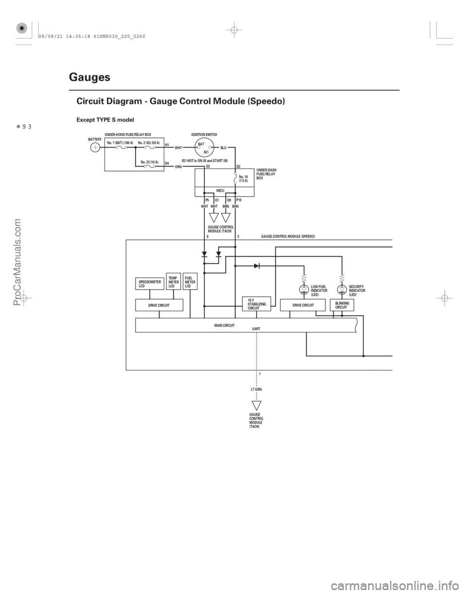
Except TYPE S model
22-258Gauges
Circuit Diagram - Gauge Control Module (Speedo)
UART
No. 10
(7.5 A)
No. 1 (BAT) (100 A)
IGNITION SWITCH
BATTERY
No. 23 (10 A)WHT
BLU
BAT
IG1
ORN
No. 2 (IG) (50 A)
BRN
WHT BRN
UNDER-HOOD FUSE/RELAY BOX
IG1 HOT in ON (II) and START (III)
WHT
DRIVE CIRCUIT DRIVE CIRCUIT
5
MAIN CIRCUIT LT GRN7GAUGE CONTROL MODULE (SPEEDO)
6
BLINKING
CIRCUIT
GAUGE
CONTROL
MODULE
(TACH)
10 V
STABILIZING
CIRCUIT
LOW FUEL
INDICATOR
(LED)
SECURITY
INDICATOR
(LED)
FUEL
METER
LCD
TEMP
METER
LCD
SPEEDOMETER
LCD GAUGE CONTROL
MODULE (TACH)UNDER-DASH
FUSE/RELAY
BOX
H1
D4 G2D2
P5 Q1 Q9P10
MICU
08/08/21 14:35:18 61SNR030_220_0260
ProCarManuals.com
DYNOMITE -2009-
Page 2210 of 2893
������(�#�'���������������
�����������������������)���
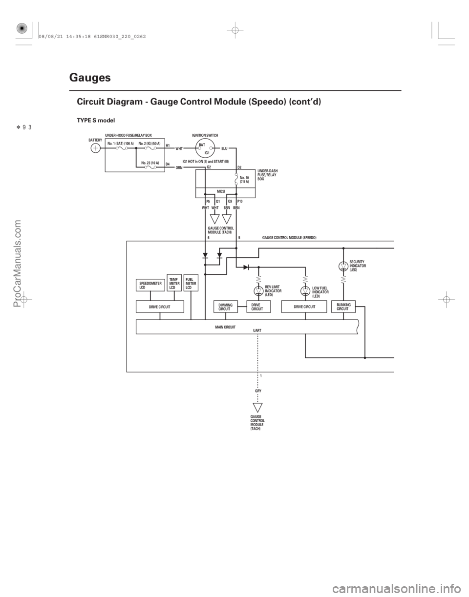
TYPE S model
22-260Gauges
Circuit Diagram - Gauge Control Module (Speedo) (cont’d)
UART
No. 10
(7.5 A)
No. 1 (BAT) (100 A)
IGNITION SWITCH
BATTERY
No. 23 (10 A)WHT
BLU
BAT
IG1
ORN
No. 2 (IG) (50 A)
BRN
WHT BRN
UNDER-HOOD FUSE/RELAY BOX
IG1 HOT in ON (II) and START (III)
WHT
DRIVE CIRCUIT DRIVE CIRCUIT
5
MAIN CIRCUIT GRY1GAUGE CONTROL MODULE (SPEEDO)
6
BLINKING
CIRCUIT
GAUGE
CONTROL
MODULE
(TACH) LOW FUEL
INDICATOR
(LED)
SECURITY
INDICATOR
(LED)
FUEL
METER
LCD
TEMP
METER
LCD
SPEEDOMETER
LCD GAUGE CONTROL
MODULE (TACH)UNDER-DASH
FUSE/RELAY
BOX
H1
D4 G2D2
P5 Q1 Q9P10
REV LIMIT
INDICATOR
(LED)
DIMMING
CIRCUIT DRIVE
CIRCUIT
MICU
08/08/21 14:35:18 61SNR030_220_0262
ProCarManuals.com
DYNOMITE -2009-
Page 2213 of 2893
����
�µ
�µ �µ
�µ
DTC B1155:
DTC B1156:
DTC B1159:
DTC B1188:
YES
NO YES
NO
22-263
Gauge Control Module Lost
Communication with the MICU (Headlight
Swi")
�(�#�'��������� �������������.�
�
�����������)����
�µ
�µ �µ
�µ
DTC B1155:
DTC B1156:
DTC B1159:
DTC B1188:
YES
NO YES
NO
22-263
Gauge Control Module Lost
Communication with the MICU (Headlight
Switch Message)
Gauge Control Module Lost
Communication with the MICU (Wiper Switch
Message)
Gauge Control Module Lost
Communication with the MICU (DOORSW
Message)
Gauge Control Module Lost
Communication with the MICU (RM
Message)
NOTE: If you are troubleshooting multiple DTCs, be
sure to follow the instructions in B-CAN System
Diagnosis Test Mode A (see page 22-93).
1. Clear the DTCs with the HDS.
2. Turn the ignition switch to LOCK (0), and then back to ON (II).
3. Check for DTCs with the HDS.
Go to step 4.
Intermittent failure. The gauge control
module is OK at this time. Check for loose or poor
connections. If the connections are good, check the
battery condition (see page 22-67), and the
charging system. 4. Check for DTCs with the HDS.
Faulty MICU; replace the under-dash fuse/
relay box (see page 22-66).
Replace the gauge control module (tach)
(see page 22-277).
Ar e DT Cs B115 5 , B115 6, 115 7 , B115 9, B1160, and / or B1188 i nd i cat ed ? Ar e DT Cs B115 5 , B115 6, 115 7 , B115 9, B1160,
and / or B1188 i nd i cat ed at t he same t i me?
08/08/21 14:35:19 61SNR030_220_0265
ProCarManuals.com
DYNOMITE -2009-
Page 2214 of 2893
�����(�#���������� �������������.�
�
�����������)����
�µ
�µ
�µ
�µ �µ
�µ
�µ
�µ
DTC B1157: DTC B1160:
YES
NO
YES
NO YES
NO
YES
NO
22-26422-264Gauge")
�(�#�'��������� �������������.�
�
�����������)�����(�#�'��������� �������������.�
�
�����������)����
�µ
�µ
�µ
�µ �µ
�µ
�µ
�µ
DTC B1157: DTC B1160:
YES
NO
YES
NO YES
NO
YES
NO
22-26422-264Gauges
DTC Troubleshooting (cont’d)
Gauge Control Module Lost
Communication with the MICU (MICU
Message) Gauge Control Module Lost
Communication with the MICU (DRLOCKSW
Message)
NOTE: If you are troubleshooting multiple DTCs, be
sure to follow the instructions in B-CAN System
Diagnosis Test Mode A (see page 22-93).
1. Clear the DTCs with the HDS.
2. Turn the ignition switch to LOCK (0), and then back to ON (II).
3. Check for DTCs with the HDS.
Go to step 4.
Intermittent failure. The gauge control
module is OK at this time. Check for loose or poor
connections. If the connections are good, check the
battery condition (see page 22-67), and the
charging system.
4. Check for DTCs with the HDS.
Faulty MICU; replace the under-dash fuse/
relay box (see page 22-66).
Replace the gauge control module (tach)
(see page 22-277). NOTE: If you are troubleshooting multiple DTCs, be
sure to follow the instructions in B-CAN System
Diagnosis Test Mode A (see page 22-93).
1. Clear the DTCs with the HDS.
2. Turn the ignition switch to LOCK (0), and then back to ON (II).
3. Check for DTCs with the HDS.
Go to step 4.
Intermittent failure. The gauge control
module is OK at this time. Check for loose or poor
connections. If the connections are good, check the
battery condition (see page 22-67), and the
charging system.
4. Check for DTCs with the HDS.
Faulty MICU; replace the under-dash fuse/
relay box (see page 22-66).
Replace the gauge control module (tach)
(see page 22-277).
I s DT C B115 7 i nd i cat ed ?
Ar e DT Cs B115 7 and B1165 i nd i cat ed at t he sametime? I s DT C B1160 i nd i cat ed ?
Ar e DT Cs B1160 and B1905 i nd i cat ed at t he sametime?
08/08/21 14:35:19 61SNR030_220_0266
ProCarManuals.com
DYNOMITE -2009-
Page 2222 of 2893

�¦�§ �¦ �§�¦ �§
�¦�§
�¦�§
�µ
�µ
Cavity Wire Test condition
Test: Desired result Possible cause if desired result
is not obtained
Cavity Wire Test condition Test: Desired result Possible cause if desired result
is not obtained
22-272Gauges
Gauge Control Module (Tach) Input Test (cont’d)
4. With the connector still disconnected, do these input tests at the following connector.
If any test indicates a problem, find and correct the cause, then recheck the system.
If all the input tests prove OK, go to step 5.
20
2 LT GRN
GRY Disconnect the
gauge control
module (speedo)
12P connector Check for continuity between
terminal No. 20 No. 2 and
gauge control module (speedo)
12P connector terminal No. 7
No. 1 :
There should be continuity. An open in the wire
Check for continuity to ground:
There should be no continuity. A short to ground in the wire
13 RED Combination light switch ON Attach to ground:
The illuminations of the seat
heater switches and the
ambient light should come on
full bright. Faulty LEDs
An open in the wire
14 RED Combination light switch ON Attach to ground:
The illuminations of the dash
lights, the audio unit, the
steering wheel switches, and
the climate control unit lights
should come on full bright. Faulty LEDs
An open in the wire
: TYPE S model
5. Reconnect the connector to the gauge control module (tach), and do these input tests at the following connector. If any test indicates a problem, find and correct the cause, then recheck the system.
If all the input tests prove OK, the gauge control module (tach) must be faulty; replace it.
15 BLK Under all
conditions Measure the voltage to ground:
There should be less than 0.5 V. Poor ground (G503)
An open in the wire
16 BLK Under all conditions Measure the voltage to ground:
There should be less than 0.5 V. Poor ground (G504)
An open in the wire
17 BRN Ignition switch ON (II) Measure the voltage to ground:
There should be battery voltage. Blown No. 10 (7.5 A) fuse in
the under-dash fuse/relay box
An open in the wire
18 WHT Under all conditions Measure the voltage to ground:
There should be battery voltage.
An open in the wire
4 BRN Ignition switch ON (II), ILLUMI ( )
button pressed Measure the voltage to ground:
There should be less than 1 V.
Poor ground (G501)
Faulty dash light brightness
controller and odometer
select/reset switch
An open in the wire
Ignition switch ON
(II), ILLUMI ( )
button released Measure the voltage to ground:
There should be more than 5 V.
Faulty dash light brightness
controller and odometer
select/reset switch
A short to ground in the wire
Blown No. 23 (10 A) fuse in the
under-hood fuse/relay box
08/08/21 14:35:58 61SNR030_220_0274
ProCarManuals.com
DYNOMITE -2009-