Page 2256 of 2893
����
Both mirrors Left mirror
Right mirror
Defogger
22-306Power Mirrors
Function Test
BLK
WHTGRN
WHTPNK BLU PUR
BRN
BLK
A
B
1. Remove the power win")
����
�(�#�'�������������������������������
�������)����
Both mirrors Left mirror
Right mirror
Defogger
22-306Power Mirrors
Function Test
BLK
WHTGRN
WHTPNK BLU PUR
BRN
BLK
A
B
1. Remove the power window master switch (A).
2. Disconnect the 13P connector (B) from the powermirror switch.
3. Choose the appropriate test based on the symptom:
Both mirrors don’t work, go to step 4.
Leftmirrordoesn’twork,gotostep6.
Right mirror doesn’t work, go to step 7.
4. Measure the voltage between terminal No. 2 and body ground with the ignition switch turned to ON
(II).
There should be battery voltage.
If there is no voltage, check for: – Blown No. 36 (10 A) fuse in the under-dash fuse/relay box.
– AnopenintheBRNwire.
If there is battery voltage, go to step 5.
5. Check for continuity between terminal No. 6 and body ground. There should be continuity.
If there is no continuity, check for: – AnopenintheBLKwire.
– Poor ground (G 503).
If there is continuity, check both mirrors individually as described in the next steps. 6. Connect terminals No. 2 and No. 10, and terminals
No. 5 (or No. 12) and No. 6 with jumper wires.
The left mirror should tilt down (or swing left) with
the ignition switch to ON (II).
If the left mirror does not tilt down (or does not swing left), check for an open in the PUR (or PNK)
wire between the left mirror and the 13P
connector.
If the wire is OK, check the left mirror actuator.
If the mirror neither tilts down nor swings left, repair the GRN wire.
If the mirror works properly, check the mirror switch.
7. Connect terminals No. 2 and No. 11, and terminals No. 5 (or No. 13) and No. 6 with jumper wires. The
right mirror should tilt down (or swing left) with the
ignition switch to ON (II).
If the mirror does not tilt down (or does not swing left), check for an open in the PUR (or BLU) wire
between the right mirror and the 13P connector.
If the wire is OK, check the right mirror actuator.
If the mirror neither tilts down nor swings left, repair the WHT wire.
If the mirror works properly, check the mirror switch.
8. Connect the power mirror defogger relay terminals No. 1 and No. 2 in the under-hood fuse/relay box
with a jumper wire, and measure the voltage
between mirror connectors terminal No. 1 and
body ground. There should be battery voltage and
both mirrors should warm up with the ignition
switch to ON (II). If there is no voltage or neither warms up, check for:
– AnopenintheORNwire.
– Blown No. 36 (10 A) fuse in the under-dash fuse/relay box.
If only one fails to warm up, check: – Its defogger.
– Poor ground (G 503).
If both warm up, check the defogger switch.
Wire side of female terminals
08/08/21 14:36:52 61SNR030_220_0308
ProCarManuals.com
DYNOMITE -2009-
Page 2260 of 2893
����
�(�#�'���������������
�����
�����������������)����
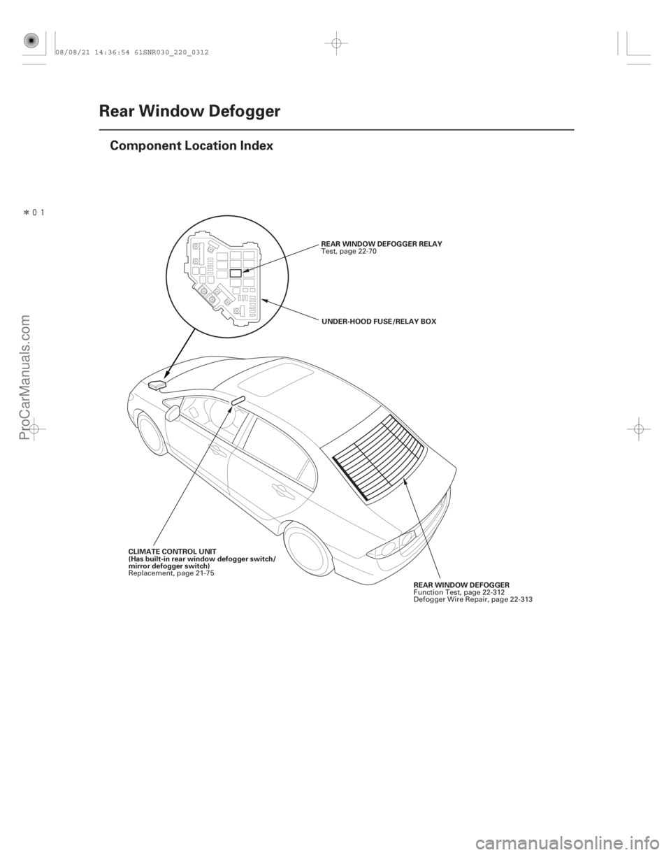
22-310Rear Window Defogger
Component Location Index
REAR WINDOW DEFOGGER RELAY
UNDER-HOOD FUSE/RELAY BOX
REAR WINDOW DEFOGGER
CLIMATE CONTROL UNIT
(Has built-in rear window defogger switch/
mirror defogger switch) Test, page 22-70
Function Test, page 22-312
Defogger Wire Repair, page 22-313
Replacement, page 21-75
08/08/21 14:36:54 61SNR030_220_0312
ProCarManuals.com
DYNOMITE -2009-
Page 2261 of 2893
����
�(�#�'���������������
�����
�����������������)����
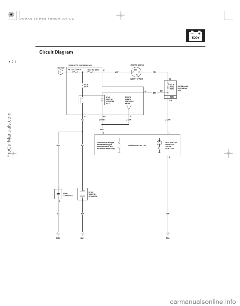
22-311
Circuit Diagram
IG2 HOT in ON (II) G12C3
CLIMATE CONTROL UNIT LT GRN
BLK
G603 2 BRN
LT GRN LT GRN
BLK No. 2 (IG) (50 A)
G801
1
RED RED UNDER-HOOD FUSE/RELAY BOX
G504BLK
RED
BRN
No. 8
(30 A)
No. 36
(HAC)
(10 A)
ORN
IGNITION SWITCH
IG2
BAT
WHT
BATTERY
No. 1 (BAT) (100 A)
UNDER-DASH
FUSE/RELAY
BOX
REAR
WINDOW
DEFOGGER
RELAY
REAR WINDOW
DEFOGGER
SWITCH
INDICATOR
(Rear window defogger
switch and defogger
timer circuit built into
the climate control unit.)
NOISE
CONDENSER REAR
WINDOW
DEFOGGER POWER
MIRROR
DEFOGGER
RELAY
H1
D1
J4 F17 F8
2 3
5
1
1 MICU
Q16
08/08/21 14:36:55 61SNR030_220_0313
ProCarManuals.com
DYNOMITE -2009-
Page 2262 of 2893
���
22-312Rear Window Defogger
Function Test
A
B
About 2.0 V About 6 V About 11 V
About 8.5 V
About 4.2 V
NOTE:
Be careful not to scratch or damage")
���
�(�#�'���������������
�����
���������
�������)���
22-312Rear Window Defogger
Function Test
A
B
About 2.0 V About 6 V About 11 V
About 8.5 V
About 4.2 V
NOTE:
Be careful not to scratch or damage the defogger wires with the tester probe.
Before testing, check the No. 8 (30 A) fuse in the under-hood fuse/relay box and the No. 36 (10 A) fuse
in the under-dash fuse/relay box.
1. Measure the voltage between the positive terminal (A) and body ground with the ignition switch turned
to ON (II) and the defogger switch ON.
There should be battery voltage.
If there is no voltage, check for: – Faulty rear window defogger relay.
– Faulty climate control unit.
– An open in the RED wire to the positive terminal.
If there is voltage, go to step 2. 2. Disconnect the negative terminal (B) from the rear
window defogger.
3. Check for continuity between the negative terminal and body ground.
If there is no continuity, check for an open in the
wire or poor ground (G 801). If there is continuity,
go to step 4.
4. Reconnect the negative terminal to the rear window defogger.
5. Turn the ignition switch to ON (II) and the rear window defogger switch ON.
6. Touch the voltmeter positive probe to each point on each defogger wire, and the negative probe to
the negative terminal.
If the voltage is as specified, the defogger wire up to that point is OK.
If the voltage is not as specified, repair the defogger wire.
– If it is more than specified at one of the points, there is a break in the negative half of the wire.
– If it is less than specified at one of the points, there is a break in the positive half of the wire.
08/08/21 14:36:55 61SNR030_220_0314
ProCarManuals.com
DYNOMITE -2009-
Page 2266 of 2893
����
�µ
�µ
�µ
22-316Immobilizer System
Circuit Diagram
LT GRN
PNK R9
F8 LT GRN
28
21
PNK
F24 G2D2
Q1
R12
PNK R6 R16 PNK
BRN/YEL C40
BRN/YEL LG1")
����
�(�#�'���������������������������������������)����
�µ
�µ
�µ
22-316Immobilizer System
Circuit Diagram
LT GRN
PNK R9
F8 LT GRN
28
21
PNK
F24 G2D2
Q1
R12
PNK R6 R16 PNK
BRN/YEL C40
BRN/YEL LG1
LG2
BRN/YEL C44 B-CAN
Q6
G504 BLK
2 1
BRN/YEL IG1
2
YEL MICU
B-CAN
VBU
K-LINE
IGKEYSW
LG
7
BLK
BRN
IG1 C36
BLK/GRN
5
LT BLU
WHT
A44
B1
B36 PG2
PG1
BLK
G101 PNK
BRN
PNK
1
No. 2 (15 A)
WHT
KEY
IMOCD
ECM/PCM UNDER-DASH FUSE/RELAY BOX
ORN IG1
BAT
BLU
No. 23 (10 A)
UNDER-HOOD FUSE/RELAY BOX
No. 2 (IG) (50 A)
BATTERY IGNITION SWITCH
No. 1 (BAT) (100 A)
IMMOBILIZER-KEYLESS CONTROL UNIT6
3 4
PGM-FI
MAIN RELAY 2
(FUEL PUMP)
DATA LINK
CONNECTOR
IGNITION
KEY SWITCH
(Closed: Key inserted)
IG1 HOT in ON (II)
and START (III)
GAUGE CONTROL
MODULE (TACH)
UNDER-DASH
FUSE/RELAY BOX IMMOBILIZER
INDICATOR
(LED)
PARKING
BRAKE
SWITCH
(Closed:
Lever pulled)
UNDER-DASH
FUSE/RELAY
BOX
D4
H1
1: CAN line
: Other communication line
*1: ’06 07 models
*2: ’07 09 models
*3: ’08 09 models
ORN
IMOES UNIT
(Built into the MICU) MICU
BLK*2
IMOCD
BLK/RED*1 BLK*3
08/08/21 14:36:58 61SNR030_220_0318
ProCarManuals.com
DYNOMITE -2009-
Page 2267 of 2893
�����µ
�µ
�µ
�µ
DTC B1905:
YES
NO
YES
NO
22-317
DTC Troubleshooting
Immobilizer-Keyless Control Unit
Lost Communication with MICU (DRLOCKSW
Message)
N")
�(�#�'��������� �������������.�
�������������)�����µ
�µ
�µ
�µ
DTC B1905:
YES
NO
YES
NO
22-317
DTC Troubleshooting
Immobilizer-Keyless Control Unit
Lost Communication with MICU (DRLOCKSW
Message)
NOTE: If you are troubleshooting multiple DTCs, be
sure to follow the instructions in B-CAN System
Diagnosis Test Mode A (see page 22-93).
1. Clear the DTCs with the HDS.
2. Turn the ignition switch to LOCK (0), and then back to ON (II).
3. Wait for 6 seconds or more.
4. Check for DTCs with the HDS.
Go to step 5.
Intermittent failure, the system is OK at this
time. Check for loose or poor connections at the
immobilizer-keyless control unit 7P c onnector, and
the under-dash fuse/relay box connector Q (16P).
5. Check for DTCs with the HDS.
Faulty MICU; replace the under-dash fuse/
relay box (see page 22-66).
Replace the immobilizer-keyless control unit
(see page 22-332).
Is DTC B1905 indicated?
Is DT C B1160 also indicated with DT C B1905?
08/08/21 14:36:58 61SNR030_220_0319
ProCarManuals.com
DYNOMITE -2009-
Page 2269 of 2893
����
�µ
�µ �µ
�µ
�µ
�µ
DTC B1925:
YES
NO YES
NO
YES
NO
22-319
IGNITION KEY SWITCH 6P CONNECTOR
GND
IG KEY SW
IGNITION KEY SWITCH 6P CONNEC")
���
����
�(�#�'��������� �������������.�
�������������)����
�µ
�µ �µ
�µ
�µ
�µ
DTC B1925:
YES
NO YES
NO
YES
NO
22-319
IGNITION KEY SWITCH 6P CONNECTOR
GND
IG KEY SW
IGNITION KEY SWITCH 6P CONNECTOR GND
IG KEY SW
Ignition Key Switch Signal Error
NOTE:
If you are troubleshooting multiple DTCs, be sure to follow the instructions in B-CAN System Diagnosis
Test Mode A (see page 22-93).
If the vehicle is equipped with an ACURA ACCESSORY remote starter, this DTC is normal no
further diagnosis is necessary.
1. Clear the DTCs with the HDS.
2. Turn the ignition switch to LOCK (0) and remove the ignition key.
3. Insert the ignition key into the ignition switch, and turn the ignition switch to ON (II).
4. Check for DTCs with the HDS.
Go to step 5.
Intermittent failure, the system is OK at this
time. Check for loose or poor connections at the
immobilizer-keyless control unit 7P c onnector,
under-dash fuse/relay box 20P connector R, and at
the ignition key switch 6P connector.
5. Turn the ignition switch to LOCK (0) and remove the ignition key.
6. Disconnect the ignition key switch 6P connector. 7. At the ignition key switch side, check for continuity
between ignition key switch 6P connector terminals
No. 1 and No. 2.
Faulty ignition key switch or short to ground,
replace the steering lock assembly (see page 17-14).
Go to step 8.
8. Insert the ignition key into the ignition switch.
9. At the ignition key switch side, check for continuity between ignition key switch 6P connector terminals
No. 1 and No. 2.
Go to step 10.
Faulty ignition key switch, replace the
steering lock assembly (see page 17-14).
(cont’d)
Terminal side of male terminals
Terminal side of male terminals
Is DTC B1925 indicated? Is there continuity?
Is there continuity?
08/08/21 14:36:59 61SNR030_220_0321
ProCarManuals.com
DYNOMITE -2009-
Page 2270 of 2893

IGNITION KEY SWITCH 6P CONNECTOR
IMMOBILIZER-KEYLESS CONTROL UNIT 7P CONNECTOR IG KEY SW (PNK)
IG KEY SW")
��������
�µ
�µ �µ
�µ
YES
NO YES
NO
22-320Immobilizer System
DTC Troubleshooting (cont’d)
IGNITION KEY SWITCH 6P CONNECTOR
IMMOBILIZER-KEYLESS CONTROL UNIT 7P CONNECTOR IG KEY SW (PNK)
IG KEY SW (PNK) IMMOBILIZER-KEYLESS CONTROL UNIT 7P CONNECTOR
IG KEY SW (PNK)
10. Disconnect the immobilizer-keyless control unit 7Pconnector.
11. Check for continuity between immobilizer-keyless control unit 7P connector terminal No. 6 and
ignition key switch 6P connector terminal No. 1.
Go to step 12.
Repair an open in the wire and check under-
dash fuse/relay box 20P connector R. 12. Check for continuity between immobilizer-keyless
control unit 7P connector terminal No. 6 and body
ground.
Repair a short to ground in the wire or
substitute a known-good under-dash fuse/relay box,
and recheck. If the symptom/indication goes away,
replace under-dash fuse/relay box.
Replace the immobilizer-keyless control unit
(see page 22-332).
Wire side of female terminals
Wire side of female terminals Wire side of female terminals
Is there continuity?
Is there continuity?
08/08/21 14:36:59 61SNR030_220_0322
ProCarManuals.com
DYNOMITE -2009-