Page 2244 of 2893
����
�(�#�'�����������������
�
�������������������)����
22-294Accessory Power Sockets
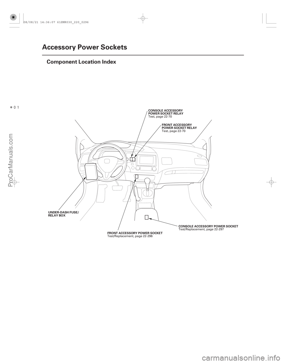
Component Location Index
FRONT ACCESSORY POWER SOCKET
FRONT ACCESSORY
POWER SOCKET RELAY
CONSOLE ACCESSORY
POWER SOCKET RELAY
CONSOLE ACCESSORY POWER SOCKET
UNDER-DASH FUSE/
RELAY BOX
Test/Replacement, page 22-296Test, page 22-70
Test, page 22-70
Test/Replacement, page 22-297
08/08/21 14:36:07 61SNR030_220_0296
ProCarManuals.com
DYNOMITE -2009-
Page 2245 of 2893
����
�(�#�'�����������������
�
�������������������)���
�µ
�µ
22-295
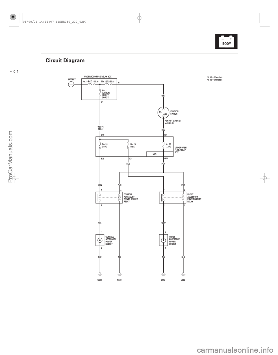
Circuit Diagram
(15 A) No. 29
BLU
G503BLK
PUR
(80 A) *1
(60 A) *2
BLK
G503
G601 YEL
BLK
1
2 PUR
GRN No. 28
(15 A) No. 2
(OPTION)
No.1(BAT)(100A) No.2(IG)(50A)
BATTERY UNDERHOOD FUSE/RELAY BOX
PUR2 1
G502 BLK
WHT (7.5 A) No. 35
RED ACC
BAT WHT
IGNITION
SWITCH
ACC HOT in ACC (I)
and ON (II)
UNDER-DASH
FUSE/RELAY
BOX
CONSOLE
ACCESSORY
POWER SOCKET
RELAY FRONT
ACCESSORY
POWER
SOCKET
CONSOLE
ACCESSORY
POWER
SOCKET FRONT
ACCESSORY
POWER SOCKET
RELAY
H1
G1
G19 C2
E35 K8 Q14
2 4
1 3 24
1
3
WHT*1
RED*2 *1: ’06 07 models
*2: ’08 09 models
MICU
08/08/21 14:36:07 61SNR030_220_0297
ProCarManuals.com
DYNOMITE -2009-
Page 2246 of 2893
����
22-296 Accessory Power Sockets
Front Accessory Power Socket Test/Replacement
BLK
WHT
A B
A
A
NOTE: If both of the front and console acc")
���
����
����
�(�#�'�����������������
�
���
���������������)����
22-296 Accessory Power Sockets
Front Accessory Power Socket Test/Replacement
BLK
WHT
A B
A
A
NOTE: If both of the front and console accessory power
sockets do not work, check the No. 35 (7.5 A) fuse in the
under-dash fuse/relay box. 1. Remove the center panel. With audio:– ’06-08 models (see page 23-80)
– ’09 model (see page 23-256)
With navigation: – ’06-08 models (see page 23-155)
– ’09 model (see page 23-355)
2. Disconnect the 2P connector (A) from the front accessory power socket (B).
3. Inspect the connector terminals to be sure they are all making good contact.
If the terminals are bent, loose, or corroded, repair them as necessary and recheck the system.
IftheterminalslookOK,gotostep4.
4. Turn the ignition switch to ACC (I).
5. Measure the voltage between front accessory power socket 2P connector terminal No. 1 and body
ground. There should be battery voltage.
If there is battery voltage, go to step 6.
If there is no voltage, check for: – Blown No. 29 (15 A) fuse in the under-dash fuse/relay box.
– Faulty front accessory power socket relay.
– Poor ground (G 503).
– Anopeninthewire. 6. Check for continuity between front accessory
power socket 2P connector terminal No. 2 and body
ground. There should be continuity.
If there is continuity, replace the power socket; go to step 7.
If there is no continuity, check for: – Poor ground (G 502).
– Anopeninthewire.
7. Remove the socket (A).
8. Remove the housing (A) from the panel.
9. Install the front accessory power socket in the reverse order of removal.
Wire side of
female terminals
08/08/21 14:36:08 61SNR030_220_0298
ProCarManuals.com
DYNOMITE -2009-
Page 2247 of 2893
����
22-297
Console Accessory Power Socket Test/Replacement
BLK
YEL
A
B
A
A
NOTE: If both of the front and console accessory power
socket")
����
����
����
�(�#�'�����������������
�
���
�������
�������)����
22-297
Console Accessory Power Socket Test/Replacement
BLK
YEL
A
B
A
A
NOTE: If both of the front and console accessory power
sockets do not work, check the No. 35 (7.5 A) fuse in the
under-dash fuse/relay box. 1. Remove the center console (see page 20-95).
2. Disconnect the 2P connector (A) from the console accessory power socket (B).
3. Inspect the connector terminals to be sure they are all making good contact.
If the terminals are bent, loose, or corroded, repair them as necessary and recheck the system.
IftheterminalslookOK,gotostep4.
4. Turn the ignition switch to ACC (I), and measure the voltage between console accessory power socket
2P connector terminal No. 1 and body ground.
There should be battery voltage.
If there is battery voltage, go to step 5.
If there is no voltage, check for: – Blown No. 28 (15 A) fuse in the under-dash fuse/relay box.
– Faulty console accessory power socket relay.
– Poor ground (G 503).
– Anopeninthewire. 5. Check for continuity between console accessory
power socket 2P connector terminal No. 2 and body
ground. There should be continuity.
If there is continuity, replace the power socket; go to step 6.
If there is no continuity, check for: – Poor ground (G 601).
– Anopeninthewire.
6. Remove the socket (A).
7. Remove the housing (A) from the panel.
8. Install the console accessory power socket in the reverse order of removal.
Wire side of
female terminals
08/08/21 14:36:08 61SNR030_220_0299
ProCarManuals.com
DYNOMITE -2009-
Page 2250 of 2893
������(�#�'�����"���������
�����������������������)����
22-300Seat Heaters
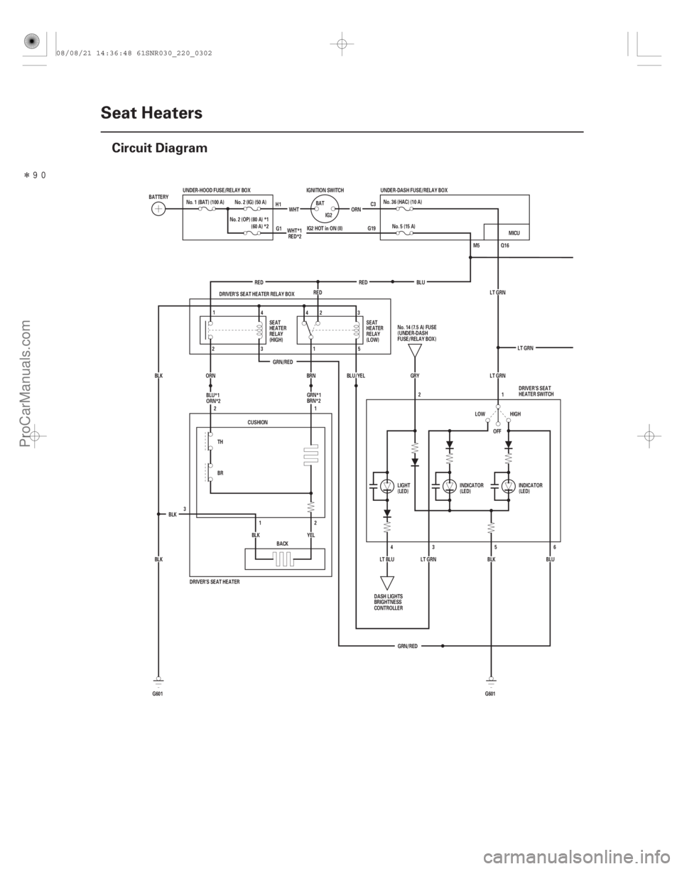
Circuit Diagram
Q16
IG2 HOT in ON (II) G19 C3
M5
LT GRN
GRN/RED LT GRN
OFF 1
2
GRN/RED LT GRN
6
5
3
BLU
BLK HIGH
LOW
4
LT BLU GRY
LT GRN
DRIVER’S SEAT HEATER
3
YEL
BLK
BLK BLK CUSHION
1
2
2
1
BACK
BR TH DRIVER’S SEAT HEATER RELAY BOX
BLU/YEL
BRN
ORN
BLK RED
RED
RED No. 5 (15 A)
No.36(HAC)(10A)
G601
G601 IGNITION SWITCH
IG2
BAT
ORN
WHT
UNDER-HOOD FUSE/RELAY BOX
No. 2 (IG) (50 A)
No. 1 (BAT) (100 A)
BATTERY UNDER-DASH FUSE/RELAY BOX
SEAT
HEATER
RELAY
(HIGH) SEAT
HEATER
RELAY
(LOW)
No.14(7.5A)FUSE
(UNDER-DASH
FUSE/RELAY BOX)
DASH LIGHTS
BRIGHTNESS
CONTROLLER LIGHT
(LED)
INDICATOR
(LED)DRIVER’S SEAT
HEATER SWITCH
INDICATOR
(LED)
H1
G1
1 4
2 343
1 5
2
No. 2 (OP) (80 A) *1
(60 A) *2 WHT*1
RED*2
BLU
BLU*1
ORN*2 GRN*1
BRN*2 MICU
08/08/21 14:36:48 61SNR030_220_0302
ProCarManuals.com
DYNOMITE -2009-
Page 2251 of 2893
�����
�µ
�µ
�¦�µ �µ �§
�¦�µ �µ�§
�¦�µ �µ�§ �¦�µ �µ�§
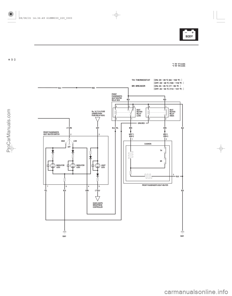
22-301
GRN/REDRED
OFF 3
BLU
RED
BLK
ORN
BRN
BLU/YEL
TH
BR2
1
CUSHION
BLKBLK
FRONT PASSENGER’S SEAT HEATER
LT GRN GRY
LT BLU5
LOW
HIGH
BLK
YEL 4
6
7
GRN3
2
FRONT PASSENGER’S
SEAT HEATER SWITCH
DASH LIGHTS
BRIGHTNESS
CONTROLLER
No. 14 (7.5 A) FUSE
(UNDER-DASH
FUSE/RELAY BOX)
SEAT
HEATER
RELAY
(LOW)SEAT
HEATER
RELAY
(HIGH)
FRONT
PASSENGER’S
SEAT HEATER
RELAY BOX
INDICATOR
(LED) INDICATOR
(LED) LIGHT
(LED)32
4
5 1 4
1
3 2
RED
WHT*1BRN*2 *1: ’06 07 models
*2: ’08 09 models
RED*1
ORN*2
G601
G601
TH: THERMOSTAT
BR: BREAKER ON: 29 39 °C (84 102 °F)
OFF: 38 48 °C (100 118 °F)
OFF: 45 55 °C (113 131 °F) ON: 25 35 °C (77 95 °F)
08/08/21 14:36:49 61SNR030_220_0303
ProCarManuals.com
DYNOMITE -2009-
Page 2254 of 2893
�����
������(�#�'�������������������������������
�������)����
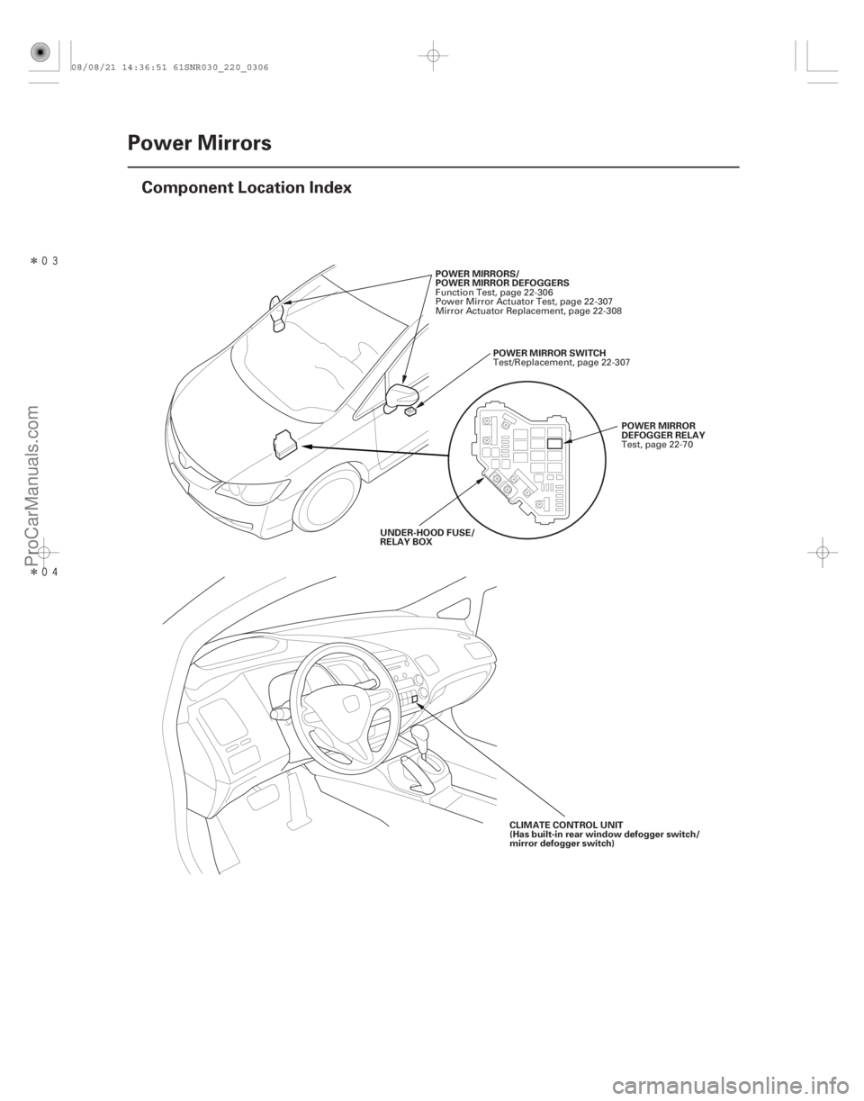
22-304Power Mirrors
Component Location Index
POWER MIRRORS/
POWER MIRROR DEFOGGERS
POWERMIRRORSWITCH
POWER MIRROR
DEFOGGER RELAY
UNDER-HOOD FUSE/
RELAY BOX
CLIMATE CONTROL UNIT
(Has built-in rear window defogger switch/
mirror defogger switch)
Function Test, page 22-306
Power Mirror Actuator Test, page 22-307
Mirror Actuator Replacement, page 22-308
Test/Replacement, page 22-307
Test, page 22-70
08/08/21 14:36:51 61SNR030_220_0306
ProCarManuals.com
DYNOMITE -2009-
Page 2255 of 2893
���
�(�#�'�������������������������������
�������)����
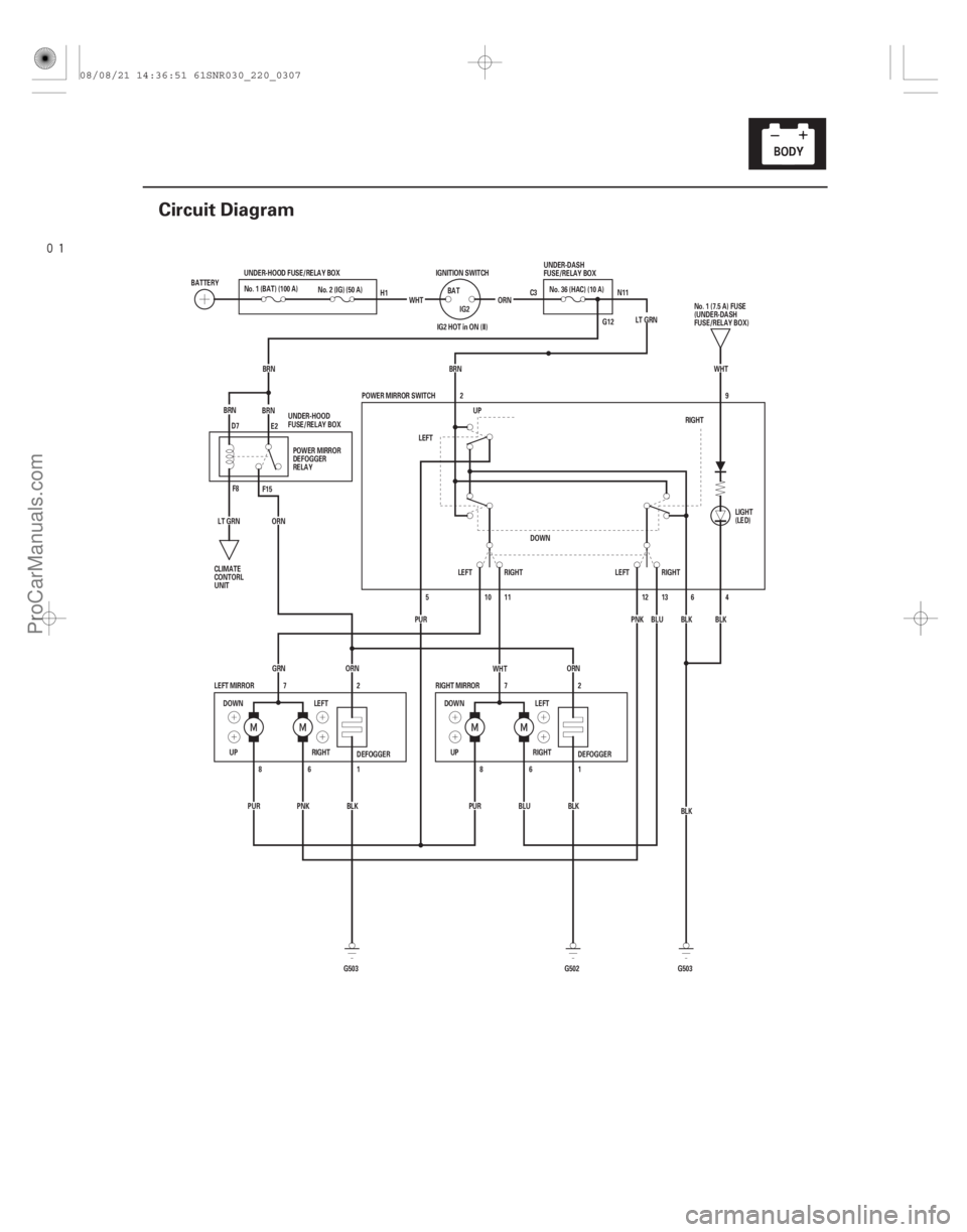
22-305
Circuit Diagram
C3 N11
G12
DEFOGGER
DEFOGGER 4
6
ORN
BRN
BRNBRN
G503 G502
PUR
PNK BLK PURBLUBLK1
6
8
1
6
8 2
7
2
7
GRN
ORN ORN
WHT
BLK
G503 BLK
BLK
UP RIGHTLEFT
DOWN
RIGHT MIRROR
LEFT MIRROR POWER MIRROR SWITCH
BRN LT GRN
IG2 HOT in ON (II)
BLU
PNK
LT GRN WHT
DOWN LEFT
RIGHT
UP IGNITION SWITCH
BAT
IG2
UNDER-HOOD FUSE/RELAY BOX
No. 2 (IG) (50 A)
BATTERY
ORN
2
DOWN RIGHT
LEFT UP
RIGHT
LEFT LEFTRIGHT
5
PUR 10 11
12 139
WHT
No. 1 (BAT) (100 A)
UNDER-DASH
FUSE/RELAY BOX
No. 1 (7.5 A) FUSE
(UNDER-DASH
FUSE/RELAY BOX)
CLIMATE
CONTORL
UNIT LIGHT
(LED)
POWER MIRROR
DEFOGGER
RELAY
UNDER-HOOD
FUSE/RELAY BOX H1
D7 E2
F8 F15 No.36(HAC)(10A)
08/08/21 14:36:51 61SNR030_220_0307
ProCarManuals.com
DYNOMITE -2009-