Page 2225 of 2893

�¦�§ �¦ �§�¦ �§
�¦�§ �¦�§
�¦�§ Cavity Wire Test condition
Test: Desired result Possible cause if desired result
is not obtained
Cavity Wire Test condition Test: Desired result Possible cause if desired result
is not obtained
22-275
4. With the connector still disconnected, do these input tests at the following connector.
If any test indicates a problem, find and correct the cause, then recheck the system.
If all the input tests prove OK, go to step 5.
11 BLU Ignition switch ON,
turn signal switch
in LEFT Measure the voltage to ground:
There should be battery voltage
when the lights are flashing. Faulty MICU
Faulty combination light
switch
An open in the wire
12 GRN Ignition switch ON, turn signal switch
in RIGHT Measure the voltage to ground:
There should be battery voltage
when the lights are flashing. Faulty MICU
Faulty combination light
switch
An open in the wire
7
1 LT GRN
GRY Disconnect the
gauge control
module (tach) 36P
connector Check for continuity between
terminal No. 7 No. 1 and
gauge control module (tach)
36P connector terminal No. 20
No. 2 :
There should be continuity. An open in the wire
Check for continuity between
terminal No. 7 No. 1 and
body ground (gauge control
module (tach) 36P connector
disconnected):
There should be no continuity. A short to ground in the wire
: TYPE S model
5. Reconnect the connector to the gauge control module (speedo), and do these input tests at the following connector.
If any test indicates a problem, find and correct the cause, then recheck the system.
If all the input tests prove OK, the gauge control module (speedo) must be faulty; replace it.
6 WHT Under all
conditions Measure the voltage to ground:
There should be battery voltage. Blown No. 23 (10 A) fuse in
the under-hood fuse/relay
box
An open in the wire
5 BRN Ignition switch ON (II) Measure the voltage to ground:
There should be battery voltage. Blown No. 10 (7.5 A) fuse in
the under-dash fuse/relay box
An open in the wire
4 BLK Under all conditions Measure the voltage to ground:
There should be less than 0.5 V. Poor ground (G504)
An open in the wire
08/08/21 14:35:59 61SNR030_220_0277
ProCarManuals.com
DYNOMITE -2009-
Page 2232 of 2893
����
�µ�µ
�µ
22-282 Reminder Systems
Circuit Diagram
MICU
ORN
(10 A) No. 23
BLK1 2
SRS UNIT
G602
B11
A12
A11 YEL
WHT REDRED")
����
�(�#�'�������������������
�
�����������������)����
�µ�µ
�µ
22-282 Reminder Systems
Circuit Diagram
MICU
ORN
(10 A) No. 23
BLK1 2
SRS UNIT
G602
B11
A12
A11 YEL
WHT REDRED
WHT
ORN28
LT GRN BLK16
G504
INDICATOR DRIVE CIRCUIT
MICU
ECM/PCM MAIN CIRCUIT
21
PNK
124
CAN L
CAN H
CHIME
WHT
BRN
RED 19
1
WHT No. 2 (IG) (50 A)
GAUGE CONTROL MODULE (TACH) 18
17
IG1
BAT
BLU
WHT
UNDER-HOOD FUSE/RELAY BOX
BATTERY IGNITION SWITCH
No. 1 (BAT) (100 A)
(7.5 A) No. 10UNDER-DASH
FUSE/RELAY
BOX
DRIVE
CIRCUIT
PARKING
BRAKE
REMINDER
SEAT
BELT
REMINDER
KEY-IN
REMINDER
F-CAN
TRANSCEIVER B-CAN
TRANSCEIVERLIGHTS-ON
INDICATOR
(LED)
IG1 HOT in ON (II)
and START (III)
ABS MODULATOR-
CONTROL UNIT*1 LIGHTS-ON INDICATOR
DIMMING CIRCUIT
PARKING
BRAKE
SWITCH
(Closed:
Lever pulled)
DRIVER’S
SEAT BELT
BUCKLE
SWITCH
(Closed:
unbuckled) SEAT BELT
REMINDER
INDICATOR
(LED)
BRAKE
SYSTEM
INDICATOR
(LED)COMPULSORY
TURNING-ON
CIRCUIT
LIGHTS-ON
REMINDER
CLIMATE
CONTROL
UNIT
IMMOBILIZER-
KEYLESS
CONTROL UNIT
HANDSFREELINK
CONTROL UNIT*4
H1
D4 D2
Q1 Q9
G2 :CANline
1
VSA MODULATOR-
CONTROL UNIT*2
YAW RATE-LATERAL
ACCELERATION SENSOR*2
DATA LINK CONNECTOR
EPS CONTROL UNIT
TPMS CONTROL UNIT*3 10 V
STABILIZING
CIRCUIT
*1: ’06 07 Touring and Premium models
*2: ’07 TYPE S and ’08 09 models
*3: ’08 09 models
*4: ’09 model with navigation system
MICU
A
B
08/08/21 14:36:02 61SNR030_220_0284
ProCarManuals.com
DYNOMITE -2009-
Page 2233 of 2893
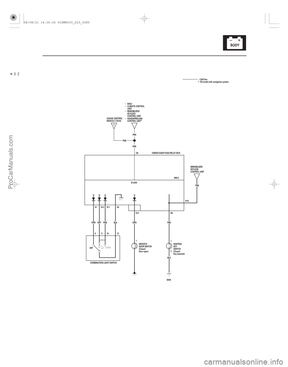
�����
22-283
R16
PNK
Q6
PNK
PNK
B-CAN PNK
R6
G504 BLK
2 1
PNK
GRN E37 MICU
UNDER-DASH FUSE/RELAY BOX
9 S1
ORN S5
S11S13
BLK
PNK
GRY
12
(
()
1011
)
OFF
COMBINATION LIGHT SWITCH DRIVER’S
DOOR SWITCH
(Closed :
Door open)
IGNITION
KEY
SWITCH
(Closed :
Key inserted)IMMOBILIZER-
KEYLESS
CONTROL UNIT
GAUGE CONTROL
MODULE (TACH)
MICU
CLIMATE CONTROL
UNIT
IMMOBILIZER-
KEYLESS
CONTROL UNIT
HANDSFREELINK
CONTROL UNIT*
1 : CAN line
*: ’09 model with navigation system
A
08/08/21 14:36:02 61SNR030_220_0285
ProCarManuals.com
DYNOMITE -2009-
Page 2234 of 2893
���
�(�#�'�������������������������
�����
�������)�
��
22-284Reminder Systems
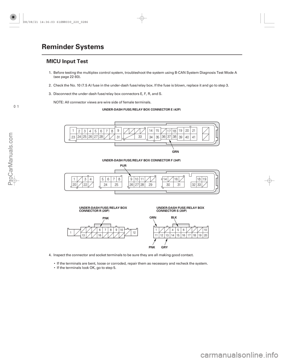
MICU Input Test
UNDER-DASH FUSE/RELAY BOX CONNECTOR E (42P)
GRN
PUR
PNK ORN
BLK
PNK GRY
UNDER-DASH FUSE/RELAY BOX
CONNECTOR R (20P) UNDER-DASH FUSE/RELAY BOX CONNECTOR F (34P)
UNDER-DASH FUSE/RELAY BOX
CONNECTOR S (20P)
1. Before testing the multiplex control system, troubleshoot the system using B-CAN System Diagnosis Test Mode A(see page 22-93).
2. Check the No. 10 (7.5 A) fuse in the under-dash fuse/relay box. If the fuse is blown, replace it and go to step 3.
3. Disconnect the under-dash fuse/relay box connectors E, F, R, and S. NOTE: All connector views are wire side of female terminals.
4. Inspect the connector and socket terminals to be sure they are all making good contact. If the terminals are bent, loose or corroded, repair them as necessary and recheck the system.
IftheterminalslookOK,gotostep5.
08/08/21 14:36:03 61SNR030_220_0286
ProCarManuals.com
DYNOMITE -2009-
Page 2235 of 2893

Cavity WireTest condition Test: Desired resultPossible cause if desired result is not
obtained
22-285
5. Reconnect the connector to the under-dash fuse/relay box, and do these input tests at the following connectors.
If any test indicates a problem, find and correct the cause, then recheck the system.
If all the input tests prove OK, the MICU must be faulty; replace the under-dash fuse/relay box.
E37 GRN Driver’s door open Measure the voltage to ground:
There should be less than 0.5 V.Faulty driver’s door switch
An open in the wire
Driver’s door closed Measure the voltage to ground: There should be more than 5 V. Faulty driver’s door switch
A short to ground in the wire
R6 PNK Ignition key inserted into the ignition switch Measure the voltage to ground:
There should be less than 0.5 V. Poor ground (G504)
Faulty ignition key switch
An open in the wire
Ignition switch OFF and ignition
key removed from the ignition
switch Measure the voltage to ground:
There should be more than 5 V.
Faulty ignition key switch
A short to ground in the wire
S1 ·
S5 ORN
·
BLK Combination light switch OFF Measure the voltage between S1
and S5 terminals:
There should be less than 0.5 V. Faulty combination light switch
An open in the wire
Combination light switch in any
other position than OFF Measure the voltage between S1
and S5 terminals:
There should be more than 5 V. Faulty combination light switch
A short to ground in the wire
S11 ·
S5 PNK
·
BLK Combination light switch
(Headlight position) ON
Measure the voltage between S11
and S5 terminals:
There should be less than 0.5 V. Faulty combination light switch
An open in the wire
Combination light switch OFF Measure the voltage between S11 and S5 terminals:
There should be more than 5 V. Faulty combination light switch
A short to ground in the wire
S13 ·
S5 GRY
·
BLK Combination light switch
(SMALL position) ON
Measure the voltage between S13
and S5 terminals:
There should be less than 0.5 V. Faulty combination light switch
An open in the wire
Combination light switch OFF Measure the voltage between S13 and S5 terminals:
There should be more than 5 V. Faulty combination light switch
A short to ground in the wire
08/08/21 14:36:03 61SNR030_220_0287
ProCarManuals.com
DYNOMITE -2009-
Page 2238 of 2893
���
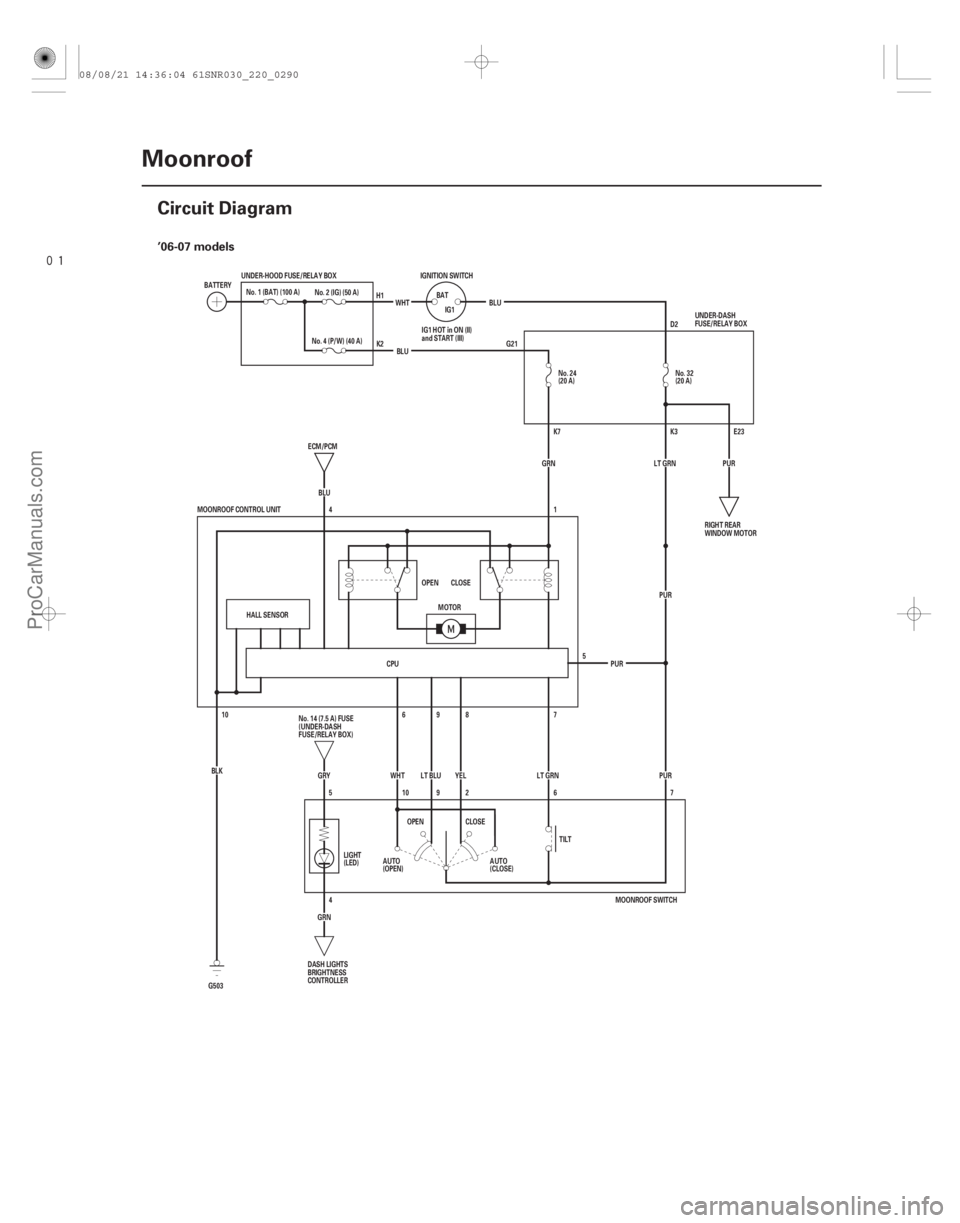
�(�#�'���������������������������������������)���� ’06-07 models
22-288Moonroof
Circuit Diagram
No. 24
(20 A)
IGNITION SWITCH
BATIG1
WHT
BLU
No. 2 (IG) (50 A)
BATTERY
No. 1 (BAT) (100 A)
(20 A)
D2
G21
E23
K3
K7
YEL
WHT
(CLOSE)
(OPEN) PUR
PUR PUR
LT GRN PUR
5
AUTO
AUTO
MOONROOF CONTROL UNIT
6
10OPEN CLOSE
HALL SENSOR
ECM/PCM
4
BLU GRN
No. 4 (P/W) (40 A)
1
10 7
8
9
7
LT BLU
CPU
MOONROOF SWITCH
BLU
G503 BLK
GRY
5 6
2
9 LT GRN
4
GRN LIGHT
(LED)
TILT
MOTOR
CLOSE
OPEN No. 32
UNDER-HOOD FUSE/RELAY BOX
RIGHT REAR
WINDOW MOTOR
No. 14 (7.5 A) FUSE
(UNDER-DASH
FUSE/RELAY BOX)
DASH LIGHTS
BRIGHTNESS
CONTROLLER UNDER-DASH
FUSE/RELAY BOX
IG1 HOT in ON (II)
and START (III)
H1
K2
08/08/21 14:36:04 61SNR030_220_0290
ProCarManuals.com
DYNOMITE -2009-
Page 2239 of 2893
����
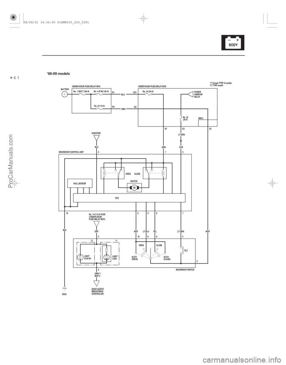
�(�#�'���������������������������������������)���� ’08-09 models
22-289
BLU
No. 4 (P/W) (40 A)
BATTERY
No. 1 (BAT) (100 A)
(20 A)
G2
G21
Q1
K7
YEL
WHT
(CLOSE)
(OPEN) WHT
PUR
LT GRN
AUTO
AUTO
MOONROOF CONTROL UNIT
6
10OPEN CLOSE
HALL SENSOR
ECM/PCM
4
BLU
GRN
1
10 7
8
9
5
LT BLU
CPU ORN
G503 BLK
GRY
3 4
8
6 LT GRN
2 TILT
MOTOR
CLOSE
OPEN No. 32
UNDER-HOOD FUSE/RELAY BOX
No. 14 (7.5 A) FUSE
(UNDER-DASH
FUSE/RELAY BOX)DASH LIGHTS
BRIGHTNESS
CONTROLLER K2
D4 No. 24 (20 A)
5POWER
WINDOW
RELAY
MICU
UNDER-DASH FUSE/RELAY BOX
K3
LIGHT
(LED)
(0.84 W) LIGHT *1: Except TYPE S models
*2: TYPE model
No. 23 (10 A)
*2 *1
MOONROOF SWITCH
GRN*1
RED*2
08/08/21 14:36:05 61SNR030_220_0291
ProCarManuals.com
DYNOMITE -2009-
Page 2241 of 2893

Cavity Wire Test conditionTest: Desired result Possible cause if desired result is
not obtained
22-291
5. Reconnect the connector to the moonroof control unit, and do these input tests at the following connector.
If any test indicates a problem, find and correct the cause, then recheck the system.
If all the input tests prove OK, go to step 6.
1 GRN Under all
conditions Measure the voltage to ground:
There should be battery voltage. Blown No. 24 (20 A) fuse in the
under-dash fuse/relay box
An open in the wire
5 PUR Ignition switch ON (II) Measure the voltage to ground:
There should be battery voltage. Blown No. 32 (20 A) fuse in the
under-dash fuse/relay box
An open in the wire
10 BLK Under all conditions Measure the voltage to ground:
There should be less than 0.5 V. Poor ground (G503)
An open in the wire
6 WHT Moonroof switch in AUTO OPEN or
AUTO CLOSE
position Measure the voltage to ground:
There should be battery voltage.
Faulty moonroof switch
Blown No. 32 (20 A) fuse in the
under-dash fuse/relay box
Blown No. 23 (10 A) fuse in the
under-hood fuse/relay box
Faulty under-dash fuse/relay
box
An open in the wire
7 LT GRN Moonroof switch in TILT position Measure the voltage to ground:
There should be battery voltage. Faulty moonroof switch
Blown No. 32 (20 A) fuse in the
under-dash fuse/relay box
Blown No. 23 (10 A) fuse in the
under-hood fuse/relay box
Faulty under-dash fuse/relay
box
An open in the wire
8 YEL Moonroof switch in CLOSE position Measure the voltage to ground:
There should be battery voltage. Faulty moonroof switch
Blown No. 32 (20 A) fuse in the
under-dash fuse/relay box
Blown No. 23 (10 A) fuse in the
under-hood fuse/relay box
Faulty under-dash fuse/relay
box
An open in the wire
9 LT BLU Moonroof switch in OPEN position Measure the voltage to ground:
There should be battery voltage. Faulty moonroof switch
Blown No. 32 (20 A) fuse in the
under-dash fuse/relay box
Blown No. 23 (10 A) fuse in the
under-hood fuse/relay box
Faulty under-dash fuse/relay
box
An open in the wire
1: ’06-07 models
2: ’08-09 models
(cont’d)
12
1 2
1 2
1 2
08/08/21 14:36:05 61SNR030_220_0293
ProCarManuals.com
DYNOMITE -2009-