Page 2177 of 2893

WIP INT/LO SW (ORN)
WIP MIST
SW (GRN) WIP LO/HI
SW (WHT) UNDER-DASH FUSE/RELAY BOX CONNECTOR S (20P)
WIP")
����
�����
�µ
�µ �µ
�µ
YES
NO YES
NO
22-227
UNDER-DASH FUSE/RELAY BOX CONNECTOR S (20P)
WIP INT/LO SW (ORN)
WIP MIST
SW (GRN) WIP LO/HI
SW (WHT) UNDER-DASH FUSE/RELAY BOX CONNECTOR S (20P)
WIP INT/
LO SW
(ORN)
WIP MIST
SW (GRN) WIP LO/HI
SW (WHT)
COMBI GND (BLK)
COMBI GND (BLK)
COMBI GND (BLK)
14. Turn the ignition switch to LOCK (0).
15. Disconnect under-dash fuse/relay box connector S
(20P).
16. Check for continuity between body ground and under-dash fuse/relay box connector S (20P)
terminals No. 10, No. 15, and No. 20 individually.
Repair a short to ground in the wire.
Go to step 17. 17. Check for continuity between under-dash fuse/relay
box connector S (20P) terminal No. 4 and terminals
No. 10, No. 15, and No. 20 individually.
Repair a short between the wires.
Faulty MICU; replace the under-dash fuse/
relay box (see page 22-66).
Wire side of female terminals Wire side of female terminals
Is there continuity?
Is there continuity?
08/08/21 14:28:47 61SNR030_220_0229
ProCarManuals.com
DYNOMITE -2009-
Page 2178 of 2893
���
�(�#�'�������������������������
�����
�������)����
22-228Wipers/Washers
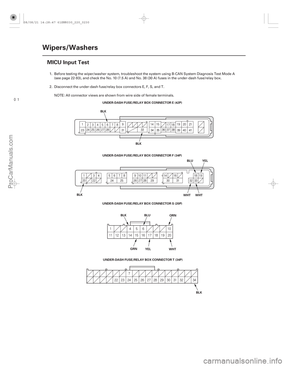
MICU Input Test
UNDER-DASH FUSE/RELAY BOX CONNECTOR E (42P)
YEL
GRN ORN
BLK
BLU
WHT
UNDER-DASH FUSE/RELAY BOX CONNECTOR F (34P)
UNDER-DASH FUSE/RELAY BOX CONNECTOR S (20P) YEL
BLK BLK
BLK WHT WHT
UNDER-DASH FUSE/RELAY BOX CONNECTOR T (34P) BLK
BLU
1. Before testing the wiper/washer system, troubleshoot the system using B-CAN System Diagnosis Test Mode A
(see page 22-93), and check the No. 10 (7.5 A) and No. 38 (30 A) fuses in the under-dash fuse/relay box.
2. Disconnect the under-dash fuse/relay box connectors E, F, S, and T. NOTE: All connector views are shown from wire side of female terminals.
08/08/21 14:28:47 61SNR030_220_0230
ProCarManuals.com
DYNOMITE -2009-
Page 2180 of 2893

5. Reconnect the connectors to the under-dash fuse/relay")
Cavity Wire Test conditionTest: Desired result Possible cause if desired result
is not obtained
22-230Wipers/Washers
MICU Input Test (cont’d)
5. Reconnect the connectors to the under-dash fuse/relay box, and do these input tests at the following connectors.
If any test indicates a problem, find and correct the cause, then recheck the system.
If all the input tests prove OK, the MICU must be faulty; replace the under-dash fuse/relay box.
E6 BLK Under all conditions Measure the voltage to ground:
There should be less than 0.5 V.Poor ground (G602)
An open in the wire
E33 BLK Under all conditions Measure the voltage to ground: There should be less than 0.5 V.Poor ground (G601)
An open in the wire
F20 BLK Under all conditions Measure the voltage to ground: There should be less than 0.5 V.Poor ground (G401)
An open in the wire
T34 BLK Under all conditions Measure the voltage to ground: There should be less than 0.5 V.Poor ground (G501)
An open in the wire
S10 ·
S4 ORN
·
BLK Ignition switch ON (II),
windshield wiper/
washer switch (INT)
ON Measure the voltage between
terminals S10 and S4, and
terminals S20 and S4:
There should be less than 1 V. Faulty windshield wiper/
washer switch
An open in the wire
Ignition switch ON (II),
windshield wiper/
washer switch OFF Measure the voltage between
terminals S10 and S4, and
terminals S20 and S4:
There should be more than 5 V. Faulty windshield wiper/
washer switch
A short to ground in the wire
S15 ·
S4 GRN
·
BLK Ignition switch ON (II),
windshield wiper/
washer switch (MIST)
ON Measure the voltage between
terminals S15 and S4:
There should be less than 1 V.
Faulty windshield wiper/
washer switch
An open in the wire
Ignition switch ON (II),
windshield wiper/
washer switch (MIST)
OFF Measure the voltage between
terminals S15 and S4:
There should be more than 5 V.
Faulty windshield wiper/
washer switch
A short to ground in the wire
S17 ·
S4 YEL
·
BLK Ignition switch ON (II),
windshield washer
switch ON Measure the voltage between
terminals S17 and S4:
There should be less than 1 V. Faulty windshield wiper/
washer switch
An open in the wire
Ignition switch ON (II),
windshield washer
switch OFF Measure the voltage between
terminals S17 and S4:
There should be more than 5 V. Faulty windshield wiper/
washer switch
A short to ground in the wire
S20 ·
S4 WHT
·
BLK Ignition switch ON (II),
windshield wiper/
washer switch (LOW)
ON Measure the voltage between
terminals S20 and S4:
There should be less than 1 V.
Faulty windshield wiper/
washer switch
An open in the wire
Ignition switch ON (II),
windshield wiper/
washer switch OFF Measure the voltage between
terminals S20 and S4:
There should be more than 5 V. Faulty windshield wiper/
washer switch
A short to ground in the wire
Ignition switch ON (II),
windshield wiper/
washer switch (HIGH)
ON Measure the voltage between
terminals S20 and S4:
There should be less than 1 V.
Faulty windshield wiper/
washer switch
An open in the wire
Ignition switch ON (II),
windshield wiper/
washer switch OFF Measure the voltage between
terminals S20 and S4:
There should be more than 5 V. Faulty windshield wiper/
washer switch
A short to ground in the wire
08/08/21 14:28:48 61SNR030_220_0232
ProCarManuals.com
DYNOMITE -2009-
Page 2191 of 2893
����
Entering the self-diagnostic function with the HDS
Entering the self-diagnostic function (manual method)
22-241
Self-diagnostic Function
ON (I")
����
�(�#�'���������������
�����������������������)����
Entering the self-diagnostic function with the HDS
Entering the self-diagnostic function (manual method)
22-241
Self-diagnostic Function
ON (II)
OFF ON
OFF ON
Ignition
Switch
Lighting
Switch
SEL/RESET
Switch
5sec.
5sec.
LOCK (0)
Before troubleshooting the gauge system, refer to multiplex integrated control system B-CAN System Diagnosis Test
Mode A (see page 22-93).
The gauge control module (tach) has a self-diagnostic function shown, and also has a customizable reset function.
The beeper drive circuit check.
The indicator drive circuit check.
The switch input test.
The LCD segments check.
The gauges drive circuit check (Tachometer, Fuel gauge, Coolant temperature gauge).
The communication line check (B-CAN, F-CAN, and UART lines).
NOTE: Indicators are also controlled via the communication line.
Using the HDS, select Body Electrical, Gauges, then Function Test and do the self-diagnostic function.
Before doing the self-diagnostic function, check the No. 10 (7.5 A) fuse in the under-dash fuse/relay box and the No. 23
(10 A) fuse in the under-hood fuse/relay box. 1. Push and hold the SEL/RESET switch button.
2. Turn the headlights ON.
3. Turn the ignition switch to ON (II).
4. Within 5 sec., turn the headlights OFF, then ON and OFF again.
5. Within 5 sec., release the SEL/RESET switch button, and then push and release the button three times repeatedly.
NOTE: While in the self-diagnostic mode, the dash lights brightness controller operates normally.
While in the self-diagnostic mode, the SEL/RESET switch button is used to start the Beeper Drive Circuit Test and the Gauge Drive Circuit Check.
If the vehicle speed exceeds 2 km/h (1.2 mph) or the ignition switch is turned to LOCK (0), the self-diagnostic mode ends.
(cont’d)
Move to self-diagnostic mode.
08/08/21 14:35:11 61SNR030_220_0243
ProCarManuals.com
DYNOMITE -2009-
Page 2194 of 2893
����
Except TYPE S model
22-244Gauges
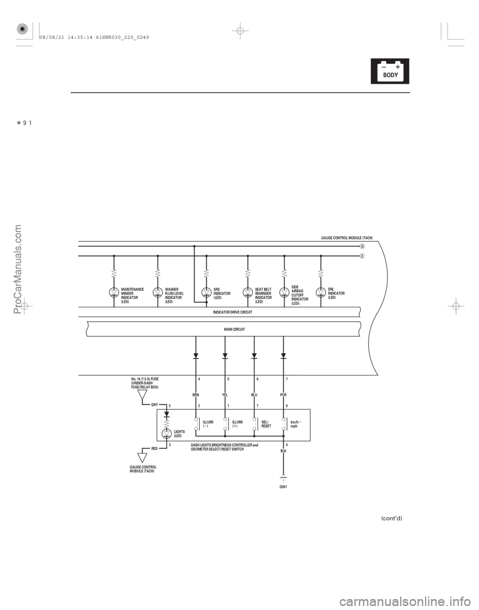
Circuit Diagram - Gauge Control Module (Tach)
UART
WHT
IG1 HOT in ON (II) and START (III)
UNDER-HOOD FUSE/REL")
������(�#�'���������������
�����������������������)����
Except TYPE S model
22-244Gauges
Circuit Diagram - Gauge Control Module (Tach)
UART
WHT
IG1 HOT in ON (II) and START (III)
UNDER-HOOD FUSE/RELAY BOX
5V
MAIN CIRCUIT
MAIN CIRCUIT
MICU
LT GRN
20
21
PNK
124
CAN L
CAN H
CHIME
BRN
WHT BRN
RED 19
1
WHT No. 2 (IG) (50 A)
GAUGE CONTROL MODULE (TACH) 18 17 TACHOMETER ORN
IG1
BAT
BLU
WHT
No. 23 (10 A)
BATTERY
IGNITION SWITCH
No. 1 (BAT) (100 A)
(7.5 A) No. 10UNDER-DASH
FUSE/RELAY
BOX
GAUGE CONTROL
MODULE (SPEEDO)
DRIVE
CIRCUIT DIMMING
CIRCUIT
PARKING
BRAKE
REMINDER
SEAT
BELT
REMINDER
KEY-IN
REMINDER
F-CAN
TRANSCEIVER B-CAN
TRANSCEIVER
IMMOBILIZER-
KEYLESS
CONTROL UNIT GAUGE
CONTROL
MODULE
(SPEEDO) 10 V
STABILIZING
CIRCUIT
HIGH BEAM
INDICATOR
(LED)
LIGHTS-ON
REMINDER
CLIMATE CONTROL
UNIT
HANDSFREELINK
CONTROL UNIT*3 IMMOBILIZER
INDICATOR
(LED)
ON/OFF
5V
5V
CONTROL
CIRCUIT
H1
D4 G2D2
Q1 P5 P10 Q9
A
ECM/PCM
ABS MODULATOR-
CONTROL UNIT*1
VSA MODULATOR-
CONTROL UNIT*2
YAW RATE-LATERAL
ACCELERATION SENSOR*2
EPS CONTROL UNIT
TPMS CONTROL UNIT*2
DATA LINK CONNECTOR
SRS UNIT
MICU
08/08/21 14:35:12 61SNR030_220_0246
ProCarManuals.com
DYNOMITE -2009-
Page 2197 of 2893
����
�µ�´�µ
22-247
G5014
3 6
7
1
2
5
BLK
PUR
7
BLU 6
YEL 5
4
BRN
GRY
RED MAIN CIRCUIT
D
INDICATOR DRIVE CIRCUIT E
MAINTENANCE
MINDER
INDICATOR
(LED) SIDE
AIRBAG
CUTOFF
INDICATOR
(LED)
ILLUMI
() ILLUMI
()SEL/
RESET km/h
mph
LIGHTS
(LED)
GAUGE CONTROL
MODULE (TACH) No. 14 (7.5 A) FUSE
(UNDER-DASH
FUSE/RELAY BOX) SEAT BELT
REMINDER
INDICATOR
(LED)
SRS
INDICATOR
(LED)
DASH LIGHTS BRIGHTNESS CONTROLLER and
ODOMETER SELECT/RESET SWITCH
WASHER
FLUID LEVEL
INDICATOR
(LED)
GAUGE CONTROL MODULE (TACH)
DRL
INDICATOR
(LED)
(cont’d)
08/08/21 14:35:14 61SNR030_220_0249
ProCarManuals.com
DYNOMITE -2009-
Page 2198 of 2893
�����
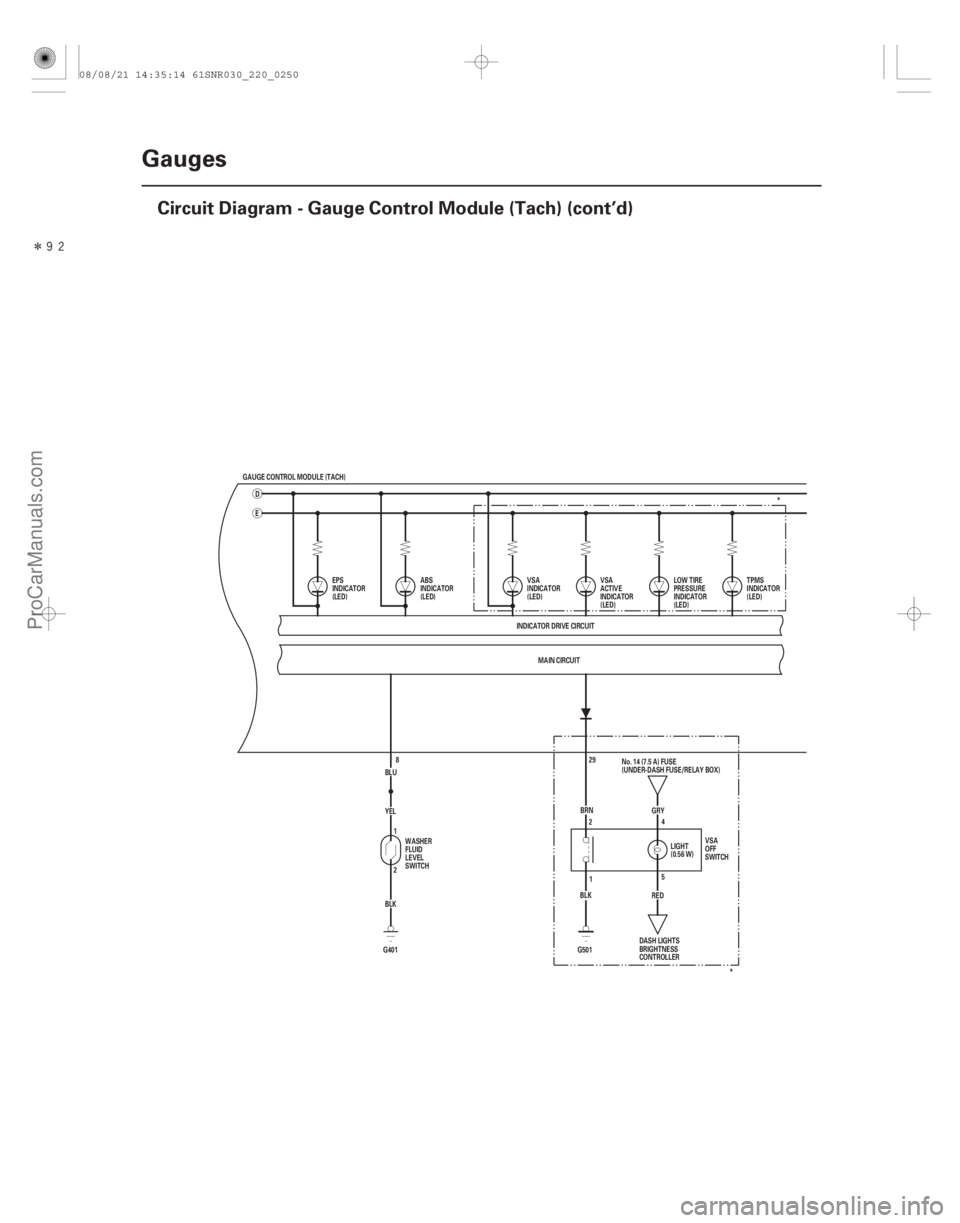
22-248Gauges
Circuit Diagram - Gauge Control Module (Tach) (cont’d)
GAUGE CONTROL MODULE (TACH)
ED
BLUYEL
BLK
G401 2 1
8 MAIN CIRCUIT
INDICATOR DRIVE CIRCUIT
EPS
INDICATOR
(LED)
LOW TIRE
PRESSURE
INDICATOR
(LED)TPMS
INDICATOR
(LED)
VSA
ACTIVE
INDICATOR
(LED)
VSA
INDICATOR
(LED)
ABS
INDICATOR
(LED)
WASHER
FLUID
LEVEL
SWITCH 5
2
4
1 RED GRY
(0.56 W) LIGHT
BRN
BLK VSA
OFF
SWITCH
DASH LIGHTS
BRIGHTNESS
CONTROLLER
G501 29
No. 14 (7.5 A) FUSE
(UNDER-DASH FUSE/RELAY BOX) *
*
08/08/21 14:35:14 61SNR030_220_0250
ProCarManuals.com
DYNOMITE -2009-
Page 2200 of 2893
����
TYPE S model
22-250Gauges
Circuit Diagram - Gauge Control Module (Tach) (cont’d)
UART
WHT
IG1 HOT in ON (II) and START (III)
UNDER-HOOD FUSE")
������(�#�'���������������
�����������������������)����
TYPE S model
22-250Gauges
Circuit Diagram - Gauge Control Module (Tach) (cont’d)
UART
WHT
IG1 HOT in ON (II) and START (III)
UNDER-HOOD FUSE/RELAY BOX
ECM
VSA MODULATOR-
CONTROL UNIT
YAW RATE-LATERAL
ACCELERATION SENSOR
EPS CONTROL UNIT
TPMS CONTROL UNIT*1
DATA LINK CONNECTOR
SRS UNIT MAIN CIRCUIT
MAIN CIRCUIT
MICU
GRY
2
21
PNK
124
CAN L
CAN H
CHIME
BRN
WHT BRN
RED 19
1
WHT No. 2 (IG) (50 A)
GAUGE CONTROL MODULE (TACH) 18 17 TACHOMETER ORN
IG1
BAT
BLU
WHT
No. 23 (10 A)
BATTERY
IGNITION SWITCH
No. 1 (BAT) (100 A)
(7.5 A) No. 10UNDER-DASH
FUSE/RELAY
BOX
GAUGE CONTROL
MODULE (SPEEDO)
DRIVE
CIRCUIT DIMMING
CIRCUIT
PARKING
BRAKE
REMINDER
SEAT
BELT
REMINDER
KEY-IN
REMINDER
F-CAN
TRANSCEIVER B-CAN
TRANSCEIVER
IMMOBILIZER-
KEYLESS
CONTROL UNIT GAUGE
CONTROL
MODULE
(SPEEDO) 10 V
STABILIZING
CIRCUIT
HIGH BEAM
INDICATOR
(LED)
LIGHTS-ON
REMINDER
CLIMATE CONTROL
UNIT
HANDSFREELINK
CONTROL UNIT*2 IMMOBILIZER
INDICATOR
(LED)
H1
D4 G2D2
Q1 P5 P10 Q9
A DRIVER DRIVERMAIN CIRCUIT
MICU
08/08/21 14:35:15 61SNR030_220_0252
ProCarManuals.com
DYNOMITE -2009-