Page 1436 of 2893
����
Removal
18-26 Front Suspension
Damper/Spring Removal and Installation
A
B
8x1.25mm
A
14x1.5mm
B A
B
C
10x1.25mm
A
1. Turn the igni")
����
���
����
����
�(�#�'�����������������������
���
���
� �����)����
Removal
18-26 Front Suspension
Damper/Spring Removal and Installation
A
B
8x1.25mm
A
14x1.5mm
B A
B
C
10x1.25mm
A
1. Turn the ignition switch to ON (II), then turn on thewindshield wipers. Turn the ignition switch to
LOCK (0) when the wipers are near the A-pillars.
2. Raise the front of the vehicle, and support it with safety stands in the proper locations (see page
1-11).
3. Remove the front wheel.
4. Remove the wheel speed sensor harness clip (A) and the brake hose bracket (B) from the damper. Do
not disconnect the wheel speed sensor connector.
5. Remove the damper pinch bolts (A) and the self- locking nuts (B) from the damper.
NOTE: Do not allow the knuckle to rotate too far
outward. This may allow the driveshaft inboard
joint come apart. 6. Remove the service cap (A) and the lid (B).
7. Remove the three flange nuts (C) from top of the
damper.
8. Remove the damper/spring (A). NOTE: The left and right damper springs are different. Mark the springs L and R before you continue.
Be careful not to damage the body.
Replace.
Replace. Replace.
08/08/21 14:57:38 61SNR030_180_0026
ProCarManuals.com
DYNOMITE -2009-
Page 1437 of 2893

’06-08 models type S model:
10x1.25mm
59N·m(6.0kgf·m,43lbf·ft)
�")
�
��
����
����
�
��
Installation
18-27
FRONT
A
B
C
A
’06-08 models except Type S model:
10x1.25mm
44N·m(4.5kgf·m,33lbf·ft)
’06-08 models type S model:
10x1.25mm
59N·m(6.0kgf·m,43lbf·ft)
’09 model:
10x1.25mm
59N·m(6.0kgf·m,43lbf·ft)
A
14x1.5mm
90 N·m
(9.2 kgf·m,
67 lbf·ft)
C
B
A
B
C
8x1.25mm
22 N·m
(2.2 kgf·m, 16 lbf·ft)1. Install the damper/spring (A) onto the frame. Note
the direction of the damper mounting base as
shown.
NOTE: Be careful not to damage the body.
2. Loosely install the new flange nuts (A). NOTE: Install the service cap (B) and the lid (C) after
tightening the flange nuts to the specified torque
value. 3. Loosely install the new damper pinch bolts (A) and
the new self-locking nuts (B) to the damper (C).
4. Raise the front suspension with a floor jack to load the suspension with the vehicle’s weight.
5. Tighten the flange nuts on top of the damper to the specified torque value.
6. Tighten the damper pinch bolts to the specified torque value.
7. Install the wheel speed sensor harness clip (A) and the brake hose bracket (B) to the damper (C).
8. Install the service cap and the lid.
9. Clean the mating surfaces of the brake disc and the inside of the wheel, then install the front wheel.
10. Check the wheel alignment, and adjust it if necessary (see page 18-5).
11. Turn the ignition switch to ON (II), then turn the windshield wipers to the default positions, and turn
the ignition switch to LOCK (0).
Replace.
Replace.
Replace.
Replace.
Replace.
08/08/21 14:57:39 61SNR030_180_0027
ProCarManuals.com
DYNOMITE -2009-
Page 1851 of 2893

Fastener Locations
:Bolt,5
A
6x1.0mm
9.8 N·m
(1.0 kgf·m,
7.2 lbf·ft) :Bolt,4
B
8x1.25mm
22 N·m
(2.2 kgf·m,
16 lbf·ft)
A
B
C
B
A AA")
���
����
20-164Exterior Trim
Cowl Cover Replacement (cont’d)
Fastener Locations
:Bolt,5
A
6x1.0mm
9.8 N·m
(1.0 kgf·m,
7.2 lbf·ft) :Bolt,4
B
8x1.25mm
22 N·m
(2.2 kgf·m,
16 lbf·ft)
A
B
C
B
A AA B
B
A
Fastener Location : Clip, 1 B
A
4. If necessary, remove the bolts (A, B), then remove the under-cowl panel (C).
5. Remove these items: Windshield wiper arms (see page 22-233)
Front fender trim, both sides (see page 20-162)
6. Detach the clip by carefully pulling the side cowl cover (A) up, then remove the cover by releasing
the hooks (B) from the front fender. Take care not to
scratch the body. Repeat this step for the other side
cowl cover, and disconnect the windshield washer
tube. 7. Install the parts in the reverse order of removal,
and note these items:
If the clips are damaged or stress-whitened, replace them with new ones.
Make sure the washer tubes are connected securely.
Make sure the windshield wipers operate normally.
Push the clips into place securely.
08/08/21 15:05:02 61SNR030_200_0166
ProCarManuals.com
DYNOMITE -2009-
Page 2036 of 2893

Keyless
Driver’s Door Switch OFF/ON
Front Passenger’s Door Switch OFF/ON
Driver")
�µ
System MenuData List Data List Indication
22-90Multiplex Integrated Control System
System Description (cont’d)
Keyless
Driver’s Door Switch OFF/ON
Front Passenger’s Door Switch OFF/ON
Driver’s Rear Door Switch OFF/ON
Passenger’s Rear Door Switch OFF/ON
Trunk Lid/Tailgate Switch OFF/ON
Front Passenger’s Door Lock Sw. (LOCK) OFF/ON
Front Passenger’s Door Lock Sw. (UNLOCK) OFF/ON
Front Passenger’s Door Lock Knob Sw. (UNLOCK) OFF/ON
Driver’s Rear Door Lock Knob Switch (UNLOCK) OFF/ON
Passenger’s Rear Door Lock Knob Sw. (UNLOCK) OFF/ON
Trunk Key Cylinder (UNLOCK) OFF/ON
Driver’s Door Key Cylinder Switch (LOCK) OFF/ON
Driver’s Door Key Cylinder Switch (UNLOCK) OFF/ON
Driver’s Door Lock Switch (LOCK) OFF/ON
Driver’s Door Lock Switch (UNLOCK) OFF/ON
Driver’s Door Lock Knob Switch (LOCK) OFF/ON
Driver’s Door Lock Knob Switch (UNLOCK) OFF/ON
Door LOCK Command OFF/ON
Door UNLOCK Command OFF/ON
Driver’s Door UNLOCK Command OFF/ON
Wipers Brake Pedal Position Switch OFF/ON
Windshield Wiper Switch (LOW) OFF/ON
Windshield Wiper Switch (HIGH) OFF/ON
Windshield Wiper Switch (MIST) OFF/ON
Windshield Wiper Switch (INT) OFF/ON
Windshield Washer Switch OFF/ON
Windshield Wiper Motor PARK Switch OFF/ON
Intermittent Wiper Dwell Timer 0.0 1.0 k /OPEN
Windshield Wiper Motor HI Command OFF/ON
Windshield Wiper Motor LO Command OFF/ON
Windshield Washer Motor Command OFF/ON
08/08/21 14:24:58 61SNR030_220_0092
ProCarManuals.com
DYNOMITE -2009-
Page 2038 of 2893

Door Locks
LOCK all doors Outputs LOCK")
�•�•�•
Function Test:
System Menu Data List Indication Data List and Operation Time
22-92Multiplex Integrated Control System
System Description (cont’d)
Door Locks
LOCK all doors Outputs LOCK signal 1 time (0.6 sec) to all doors
UNLOCK driver’s side door Outputs UNLOCK signal 1 time (0.6 sec) to driver’s
door
UNLOCK all doors Outputs UNLOCK signal 1 time (0.6 sec) to all doors
Lighting Interior Light Command Illuminates for 30 seconds.
LEFT Turn Signal Command Blinks for 5 seconds.
RIGHT Turn Signal Command Blinks for 5 seconds.
Hazard flasher Blinks turn signal (left and right) for 15 seconds.
Headlight Command Operates headlight (low) for 15 seconds.
Headlight HIGH Beam Command Operates headlight (high) for 15 seconds.
Fog Light Operates fog light relay for 15 seconds.
Parking Light Command Operates small lights for 15 seconds.
Keyless Trunk Lid/Tailgate Release Command Unlock trunk
Security Horn Command Operates horn for 1 second.
Wipers Windshield Wiper Motor LOW Command Operates windshield wiper motor for 5 seconds (low
speed).
Windshield Wiper Motor HIGH Command Operates windshield wiper motor for 5 seconds (high
speed).
Windshield Washer Command Operates windshield washer motor for 5 seconds.
Gauges Self Diagnostic Test
08/08/21 14:24:58 61SNR030_220_0094
ProCarManuals.com
DYNOMITE -2009-
Page 2171 of 2893
����
�(�#�'���������������������������������������)����
22-221
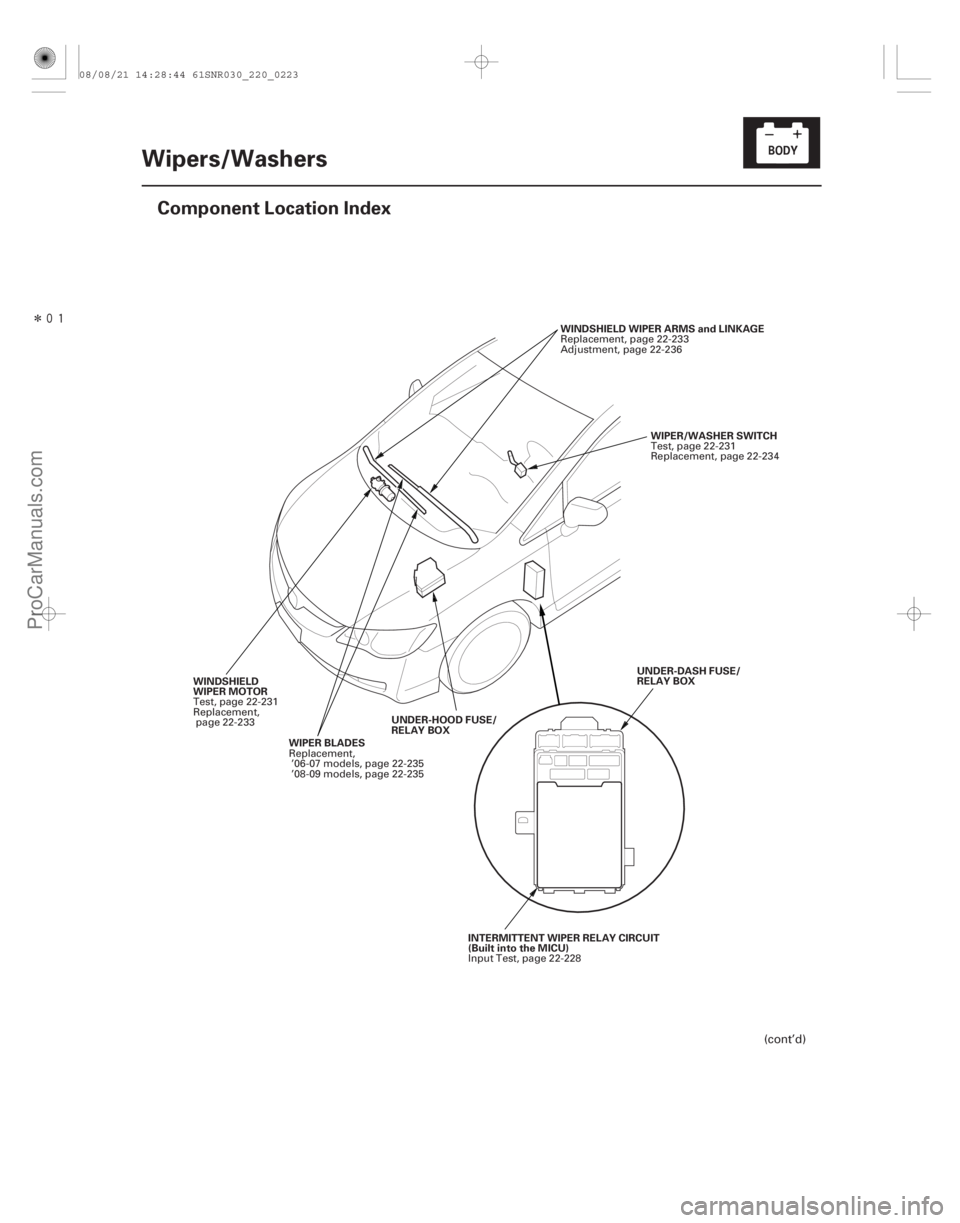
Wipers/Washers
Component Location Index
WIPER/WASHER SWITCH
WINDSHIELD WIPER ARMS and LINKAGE
WIPER BLADES UNDER-HOOD FUSE/
RELAY BOX
WINDSHIELD
WIPER MOTOR
UNDER-DASH FUSE/
RELAY BOX
INTERMITTENT WIPER RELAY CIRCUIT
(Built into the MICU)
(cont’d)
Test, page 22-231
Replacement, page 22-234
Replacement, page 22-233
Adjustment, page 22-236
Replacement, ’06-07 models, page 22-235
’08-09 models, page 22-235
Test, page 22-231
Replacement,
page 22-233
Input Test, page 22-228
08/08/21 14:28:44 61SNR030_220_0223
ProCarManuals.com
DYNOMITE -2009-
Page 2172 of 2893
�����
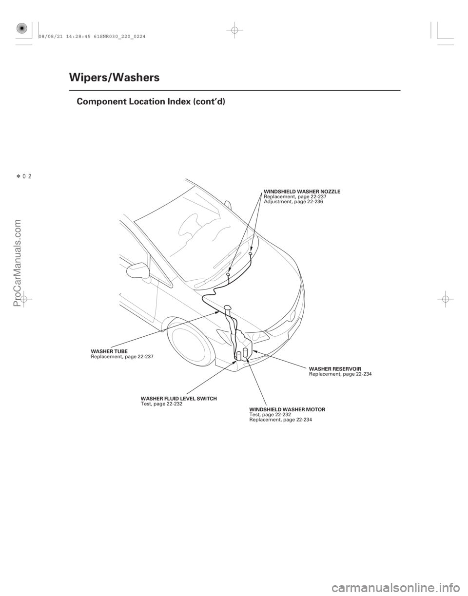
22-222Wipers/Washers
Component Location Index (cont’d)
WINDSHIELD WASHER NOZZLE
WASHER RESERVOIR
WINDSHIELD WASHER MOTOR
WASHER TUBE
WASHER FLUID LEVEL SWITCH Replacement, page 22-237
Adjustment, page 22-236
Replacement, page 22-234
Test, page 22-232
Replacement, page 22-234
Replacement, page 22-237
Test, page 22-232
08/08/21 14:28:45 61SNR030_220_0224
ProCarManuals.com
DYNOMITE -2009-
Page 2174 of 2893
����
�µ
�µ
�µ
�µ
�µ
�µ �µ
�µ
�µ
�µ
DTC B1077:
YES
NO
YES
NO
YES
NO YES
NO
YES
NO
22-224Wipers/Washers
DTC Troubleshooting
UNDER-DASH F")
���
����
�(�#�'��������� �������������.�
�������������)����
�µ
�µ
�µ
�µ
�µ
�µ �µ
�µ
�µ
�µ
DTC B1077:
YES
NO
YES
NO
YES
NO YES
NO
YES
NO
22-224Wipers/Washers
DTC Troubleshooting
UNDER-DASH FUSE/RELAY BOX CONNECTOR F (34P)
WINDSHIELD WIPER MOTOR 5P CONNECTOR AS (WHT)
AS (WHT)
WINDSHIELD WIPER MOTOR 5P CONNECTOR AS (WHT)
Windshield Wiper (As) Signal
Error
NOTE: If you are troubleshooting multiple DTCs, be
sure to follow the instructions in B-CAN System
Diagnosis Test Mode A (see page 22-93).
1. Clear the DTCs with the HDS.
2. Turn the ignition switch to LOCK (0), and then back to ON (II).
3. Turn the wiper switch to LOW or HIGH for 15 seconds or more, then turn the switch OFF.
Go to step 4.
Go to step 12.
4. Check for DTCs with the HDS.
Go to step 5.
Intermittent failure. The windshield wiper
system is OK at this time. Check for loose or poor
connections.
5. Turn the ignition switch to LOCK (0).
6. Do the wiper motor test (see page 22-231).
Go to step 7.
Replace the windshield wiper motor
(see page 22-233) and recheck.
7. Disconnect under-dash fuse/relay box connector F (34P) and windshield wiper motor 5P connector. 8. Check for continuity between windshield wiper
motor 5P connector terminal No. 5 and under-dash
fuse/relay box connector F (34P) terminal No. 32.
Go to step 9.
Repair an open in the WHT wire.
9. Check for continuity between windshield wiper motor 5P connector terminal No. 5 and body
ground.
Repair a short in the WHT wire.
Go to step 10.
Wire side of female terminals
Wire side of female terminals
Wire side of female terminals
Do t he w i nd shi el d w i per r un? Is DTC B1077 indicated?
Does t he w i per mot or r un nor mal l y and d oes i tpul se? Is there continuity?
Is there continuity?
08/08/21 14:28:46 61SNR030_220_0226
ProCarManuals.com
DYNOMITE -2009-