Page 311 of 5135

05±137
AVENSIS REPAIR MANUAL (RM1018E)
NSPEC")
A65745
STA
E12
ECM Connector
A79097
Driver Side R/B
LHDStarter Relay
A79098
Driver Side R/B
RHD
Starter Relay
±
DIAGNOSTICS SFI SYSTEM(1ZZ±FE/3ZZ±FE)
05±137
AVENSIS REPAIR MANUAL (RM1018E)
NSPECTION PROCEDURE
HINT:
This diagnostic chart is on the premise that the engine is cranked normally. If the engine is not cranked,
pro-
ceed to the problem symptoms table on page 05±22.
1 READ VALUE OF HAND±HELD TESTER(STARTER SIGNAL)
(a) Connect the hand±held tester to the DLC3.
(b) Turn the ignition switch ON and push the hand±held tester main switch \
ON.
(c) Select the item ºDIAGNOSIS / OBD/MOBD / DATA LIST / ALL / STARTER SIGº and read its value dis-
played on the hand±held tester.
Result:
Ignition Switch PositionONSTART
STA SignalOFFON
OK PROCEED TO NEXT CIRCUIT INSPECTION SHOWN ON PROBLEM SYMPTOMS TABLE
NG
2 CHECK HARNESS AND CONNECTOR(ECM ± STARTER RELAY)
(a) Disconnect the ECM E12 connector.
(b) Remove the starter relay from the driver side R/B.
(c) Check for continuity between the wire harness side con- nectors.
Standard (Check for open):
Symbols (Terminal No.)Specified condition
Starter relay (1) ± STA (E12±9)Continuity
Standard (Check for short):
Symbols (Terminal No.)Specified condition
Starter relay (1) or STA (12±9) ± Body groundNo continuity
Page 313 of 5135

G±Y
B±W
B±W
IB1 10 IC3
6
±
DIAGNOSTICS SFI SYSTEM(1ZZ±F")
A79082
53G±Y
L±B E9 10
4
5 W±B
BR F25
Fuel Pump ECM
B±W 12
FC
C8
Circuit
Opening Relay
From
Terminal 3 of
EFI Relay
(See Page 05±124)
G±Y
B±W
B±W
IB1 10 IC3
6
±
DIAGNOSTICS SFI SYSTEM(1ZZ±FE/3ZZ±FE)
05±131
AVENSIS REPAIR MANUAL (RM1018E)
FUEL PUMP CONTROL CIRCUIT
CIRCUIT DESCRIPTION
In the diagram below, when the engine is cranked, current flows from terminal ST of the igni\
tion switch to
the starter relay coil and also current flows to terminal STA of the ECM (STA signal).
When the STA signal and NE signal are input to the ECM, Tr is turned ON, current flows to the coil of the
circuit opening relay, the relay switches on, power is supplied to the fuel pump and the fuel p\
ump operates.
While the NE signal is generated (engine running), the ECM keeps Tr ON (circuit opening relay ON) and the
fuel pump also keeps operating.
WIRING DIAGRAM
INSPECTION PROCEDURE
1PERFORM ACTIVE TEST USING HAND±HELD TESTER(OPERATION OF CIRCUIT
OPENING RELAY)
(a)Turn the ignition switch ON.
(b)Select the item ºDIAGNOSIS / OBD/MOBD / ACTIVE TEST / FUEL PUMP / SPD\
º.
(c)Perform the active test with the engine stopped.
Result: The circuit opening relay operates.
OKPROCEED TO NEXT CIRCUIT INSPECTIONSHOWN ON PROBLEM SYMPTOMS TABLE
NG
2CHECK FOR ECM POWER SOURCE CIRCUIT(See page 05±124)
NG REPAIR OR REPLACE POWER SOURCE CIRCUIT
OK
05C6H±01
Page 315 of 5135

05±133
AVENSIS REPAIR MANUAL (RM10")
A66053
Engine Room R/B No.4EFI Relay
123
5
A79099
Wire Harness Side
C8
Circuit Opening Relay Connector
A65748
E9
MRELFC
±
DIAGNOSTICS SFI SYSTEM(1ZZ±FE/3ZZ±FE)
05±133
AVENSIS REPAIR MANUAL (RM1018E)
5CHECK HARNESS AND CONNECTOR(EFI RELAY ± CIRCUIT OPENING RELAY,
CIRCUIT OPENING RELAY ± ECM)
(a)Remove the EFI relay from the engine room R/B No.4.
(b)Remove the circuit opening relay.
(c)Disconnect the E9 ECM connector.
(d)Check for continuity between the wire harness side con-
nectors.
Standard (Check for open):
Symbols (Terminal No.)Specified condition
EFI relay (3) ± Circuit opening relay (C8±1)
Circuit opening relay (C8±2) ± FC (E9±10)Continuity
EFI relay (1) ± MREL (E9±8)
y
Standard (Check for short):
Symbols (Terminal No.)Specified condition
EFI relay (3) or Circuit opening relay (C8±1) ± Body ground
Circuit opening relay (C8±2) or FC (E9±10) ± Body groundNo continuity
EFI relay (1) or MREL (E9±8) ± Body ground
y
NGREPAIR OR REPLACE HARNESS OR CONNECTOR
OK
CHECK AND REPLACE ECM (See page 01±32)
6INSPECT FUEL PUMP ASSY (See page 11±8)
NG REPAIR OR REPLACE FUEL PUMP ASSY
OK
Page 320 of 5135
A79096
Driver Side J/B
IGN Fuse
A66055
Engine Room R/B No.1
IG2 Fuse
B16200
± DIAGNOSTICSSFI SYSTEM (1ZZ±FE/3ZZ±FE)
05±127
AVENSIS REPAIR MANUAL (RM1018E)
4 CHECK FUSE(IGN FUSE)
(a) Remove the IGN fuse from the driver side J/B.
(b) Check for continuity in the IGN fuse.
Standard: Continuity
NG CHECK FOR SHORT IN ALL HARNESSES AND
COMPONENTS CONNECTED FUSE
OK
5 CHECK FUSE(IG2 FUSE)
(a) Remove the IG2 fuse from the engine room R/B No.1.
(b) Check for continuity in the IG2 fuse.
Standard: Continuity
NG CHECK FOR SHORT IN ALL HARNESSES AND
COMPONENTS CONNECTED FUSE
OK
6 INSPECT IG2 RELAY
(a) Remove the IG2 relay from the engine room R/B No.4.
(b) Inspect the IG2 relay.
Standard:
Terminal No.Specified condition
1 ± 2Continuity
No Continuity
3 ± 5Continuity
(Apply battery voltage Terminals 1 and 2)
NG REPLACE IG2 RELAY
OK
Page 321 of 5135
MREL (+)
A66054
Engine Room R/B No.1
EFI Fuse
05±128
± DIAGNOSTICSSFI SYSTEM (1ZZ±FE/3ZZ±FE)
AVENSIS REPAIR MANUAL (RM1018E)
7 INSPECT")
B50489Ignition Switch
I13
A18294ECM Connecter
E12E9
E1 (±)MREL (+)
A66054
Engine Room R/B No.1
EFI Fuse
05±128
± DIAGNOSTICSSFI SYSTEM (1ZZ±FE/3ZZ±FE)
AVENSIS REPAIR MANUAL (RM1018E)
7 INSPECT IGNITION OR STARTER SWITCH ASSY
(a) Measure the resistance between the connector terminals
shown in the chart below.
SwitchTerminal No.Resisitance
LOCKAll Terminals1M� or more
ACC1±31� or less
ON1±2, 1±3, 2±3, 5±61� or less
START4±5, 4±6, 5±6, 1±21� or less
NG REPLACE IGNITION OR STARTER SWITCH
ASSY
OK
CHECK AND REPAIR HARNESS AND CONNECTOR (BATTERY ± IGNITION SWITCH, IGNITION
SWITCH ± ECM)
8 INSPECT ECM(MREL VOLTAGE)
(a) Turn the ignition switch ON.
(b) Measure the voltage between the terminals of the E9 and
E12 ECM connector.
Standard:
Symbols (Terminal No.)Specified condition
MREL (E9±8) ± E1 (E12±7)9 to 14 V
NG CHECK AND REPLACE ECM
OK
9 CHECK FUSE(EFI FUSE)
(a) Remove the EFI fuse from the engine room R/B No.1.
(b) Check for continuity in the EFI fuse.
Standard: Continuity
NG CHECK FOR SHORT IN ALL HARNESSES AND
COMPONENTS CONNECTED FUSE
OK
Page 322 of 5135
������
�
A79065
Engine Room R/B No.4
EFI No.1 Fuse
B16200
± DIAGNOSTICSSFI SYSTEM (1ZZ±FE/3ZZ±FE)
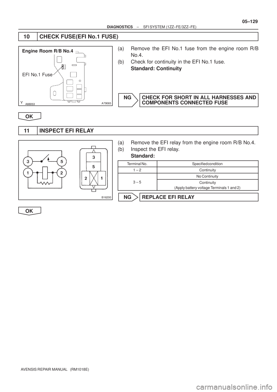
05±129
AVENSIS REPAIR MANUAL (RM1018E)
10 CHECK FUSE(EFI No.1 FUSE)
(a) Remove the EFI No.1 fuse from the engine room R/B
No.4.
(b) Check for continuity in the EFI No.1 fuse.
Standard: Continuity
NG CHECK FOR SHORT IN ALL HARNESSES AND
COMPONENTS CONNECTED FUSE
OK
11 INSPECT EFI RELAY
(a) Remove the EFI relay from the engine room R/B No.4.
(b) Inspect the EFI relay.
Standard:
Terminal No.Specified condition
1 ± 2Continuity
No Continuity
3 ± 5Continuity
(Apply battery voltage Terminals 1 and 2)
NG REPLACE EFI RELAY
OK
Page 323 of 5135

AVENSIS REPAIR MANUAL")
A66053
Engine Room R/B No.4
EFI Relay
������
�
A79066
Engine Room R/B No.4
EFI No.1 Fuse
1
2
A65748
MREL
E9
ECM Connector
+B
05±130
± DIAGNOSTICSSFI SYSTEM (1ZZ±FE/3ZZ±FE)
AVENSIS REPAIR MANUAL (RM1018E)
12 CHECK HARNESS AND CONNECTOR(EFI RELAY ± ECM, EFI RELAY ± BODY
GROUND)
(a) Check the harness and connector between the EFI relay
and ECM connector.
(1) Remove the EFI relay from the engine room R/B
No.4.
(2) Remove the EFI No.1 fuse from the engine room
R/B No.4.
(3) Disconnect the E9 ECM connector.
(4) Check for continuity between the wire harness side
connectors.
Standard (Check for open):
Symbols (Terminal No.)Specified condition
EFI relay (1) ± MREL (E9±8)
EFI relay (3) ± EFI No.1 fuse (1)Continuity
EFI No.1 fuse (2) ± +B (E9±1)
y
Standard (Check for short):
Symbols (Terminal No.)Specified condition
EFI relay (1) or MREL (E9±8) ± Body ground
EFI relay (3) or EFI No.1 fuse (1) ± Body groundNo continuity
EFI No.1 fuse (2) or +B (E9±1) ± Body ground
y
(b) Check the harness and connector between the EFI relay
and body ground.
(1) Remove the EFI relay from the engine room J/B
No.4.
(2) Check for continuity between the wire harness side
connector and the body ground.
Standard (Check for open):
Symbols (Terminal No.)Specified condition
EFI relay (2) ± Body groundContinuity
OK REPAIR OR REPLACE HARNESS OR
CONNECTOR
NG
CHECK AND REPAIR HARNESS AND CONNECTOR (TERMINAL +B OF ECM ± BATTERY POS-
ITIVE TERMINAL)
Page 325 of 5135
HT2B (+)E01 (±)E13
E10
ECM Connector
±
DIAGNOSTICS SFI SYSTEM(1AZ±FE)
05±219")
23
4 1
A79117
+B
HT
Bank 1
Sensor 2
Bank 2
Sensor 2 H8
H10
Heated Oxygen Sensor Connector
E1
OX
B16200
A18294
HT1B (+)HT2B (+)E01 (±)E13
E10
ECM Connector
±
DIAGNOSTICS SFI SYSTEM(1AZ±FE)
05±219
AVENSIS REPAIR MANUAL (RM1018E)
1INSPECT HEATED OXYGEN SENSOR(HEATER RESISTANCE)
(a)Disconnect the heated oxygen sensor connector.
(b)Inspect the heated oxygen sensor.
Standard:
Symbols (Terminal No.)ConditionSpecified condition
HT (H8±1) ± +B (H8±2)20�C (68 �F)11 to 16 �
HT (H8±1) ± E1 (H8±4)�No Continuity
HT (H10±1) ± +B (H10±2)20�C (68 �F)11 to 16 �
HT (H10±1) ± E1 (H10±4)�No Continuity
NGREPLACE HEATED OXYGEN SENSOR
OK
2INSPECT EFI RELAY
(a)Remove the EFI relay from the engine room R/B.
(b)Inspect the EFI relay. Standard:
Terminal No.Specified condition
1 ± 2Continuity
No Continuity
3 ± 5Continuity
(Apply battery voltage terminals 1 and 2)
NGREPLACE EFI RELAY
OK
3INSPECT ECM(HT1B OR HT2B VOLTAGE)
(a)Turn the ignition switch ON.
(b)Measure the voltage between the applicable terminals of the E10 and E13 ECM connector.
Standard:
Symbols (Terminal No.)Specified condition
HT1B (E10±4) ± E01 (E13±7)9to14VHT2B (E10±3) ± E01 (E13±7)9 to 14 V
HINT:
�The HT1B means the heated oxygen sensor bank 1 sen-
sor 2.
�The HT2B means the heated oxygen sensor bank 2 sen-
sor 2.
OKCHECK AND REPLACE ECM (See page 01±32)
NG

05±127
AVENSIS REPAIR MANUAL (RM1018E)
4 CHECK FUSE(IGN FUSE)
(a) Remove the I")