Page 326 of 5135
������
�
A79069
Engine Room R/B No.4
EFI No.2 Fuse
05±220
± DIAGNOSTICSSFI SYSTEM (1AZ±FE)
AVENSIS REPAIR MANUAL (RM1018E)
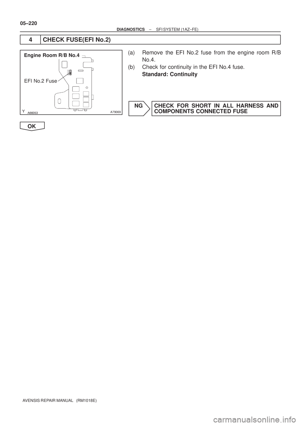
4 CHECK FUSE(EFI No.2)
(a) Remove the EFI No.2 fuse from the engine room R/B
No.4.
(b) Check for continuity in the EFI No.4 fuse.
Standard: Continuity
NG CHECK FOR SHORT IN ALL HARNESS AND
COMPONENTS CONNECTED FUSE
OK
Page 327 of 5135

A79118
Wire Harness SideBank 1
Sensor 2
Bank 2
Sensor 2 H8
H10
Heated Oxygen Sensor Connector +B
HT
A65744
HT2B
E10
ECM Connector
HT1B
������
� �
A79070
Engine Room R/B No.4
1 2
EFI No.2 Fuse
A66053
Engine Room R/B No.4
EFI Relay
±
DIAGNOSTICS SFI SYSTEM(1AZ±FE)
05±221
AVENSIS REPAIR MANUAL (RM1018E)
5CHECK HARNESS AND CONNECTOR(HEATED OXYGEN SENSOR ± ECM,
HEATED OXYGEN SENSOR ± EFI RELAY)
(a)Check the harness and connector between the ECM and
heated oxygen sensor connectors.
(1)Disconnect the H8 or H10 heated oxygen sensorconnector.
(2)Disconnect the E10 ECM connector.
(3)Check for continuity between the wire harness side connectors.
Standard (Check for open):
Symbols (Terminal No.)Specified condition
HT (H8±1) ± HT1B (E10±4)ContinuityHT (H10±1) ± HT2B (E10±3)Continuity
Standard (Check for short):
Symbols (Terminal No.)Specified condition
HT (H8±1)or HT1B (E10±4) ± Body groundNocontinuityHT (H10±1)or HT2B (E10±3) ± Body groundNo continuity
(b)Check the harness and connector between the heated oxygen sensor connector and EFI relay.
(1)Disconnect the H8 or H10 heated oxygen sensorconnector.
(2)Remove the EFI No.2 fuse from the engine room
R/B No.4.
(3)Remove the EFI relay from the engine room R/B No.4.
(4)Check for continuity between the wire harness side connectors.
Standard (Check for open):
Symbols (Terminal No.)Specified condition
+B (H8±2) ± EFI No.2 fuse (2)
+B (H10±2) ± EFI No.2 fuse (2)Continuity
EFI No.2 fuse (1) ± EFI relay (3)
y
Standard (Check for short):
Symbols (Terminal No.)Specified condition
+B (H8±2) or EFI No.2 fuse (2) ± Body ground
+B (H10±2) or EFI No.2 fuse (2) ± Body groundNo continuity
EFI No.2 fuse (1) or EFI relay (3) ± Body ground
y
NGREPAIR OR REPLACE HARNESS OR CONNECTOR
OK
CHECK AND REPLACE ECM (See page 01±32)
Page 330 of 5135

IG SW OFF Once
40 sec.
or more
60 sec.
or more 10 sec.Twice
40 sec.
or more
12 times
40 sec.
or more
10 sec.10 sec.
( � 1) (
� 3)
(� 4)
Idling( �2) (
� 3)
(� 4) (")
A58686
Vehicle speed40 km/h
(25 mph)
IG SW OFF Once
40 sec.
or more
60 sec.
or more 10 sec.Twice
40 sec.
or more
12 times
40 sec.
or more
10 sec.10 sec.
( � 1) (
� 3)
(� 4)
Idling( �2) (
� 3)
(� 4) (
� 3)
(� 5)
±
DIAGNOSTICS SFI SYSTEM(1AZ±FE)
05±213
AVENSIS REPAIR MANUAL (RM1018E)
CONFIRMATION DRIVING PATTERN
1.Connect the hand±held tester to the DLC3. ( �1)
2.Switch the hand±held tester from the normal mode to the check mode (See page 05±149). ( �1)
3. Start the engine and let the engine idle for 60 seconds or more. ( �2)
4. Drive the vehicle at 40 km/h (25 mph) or more for 40 seconds or more. \
( �3)
5. Let the engine idle for 10 seconds or more. ( �4)
6. Perform steps 4 to 5 12 times. ( �5)
HINT:
If a malfunction exists, the CHK ENG will be illuminated on the multi±\
information display during step 6.
NOTICE:
If the conditions in this test are not strictly followed, detection of t\
he malfunction will be impossible.
If you do not have a hand±held tester, turn the ignition switch OFF after performing steps from 3 to
6, then perform steps from 3 to 6 again.
INSPECTION PROCEDURE
HINT:
Hand±held tester only:
Narrowing down the trouble area is possible by performing ACTIVE TEST of the following \
ºA/F CONTROLº
(A/F sensor, heated oxygen sensor or other trouble areas can be distinguished).
(a) Perform ACTIVE TEST using the hand±held tester (A/F CONTROL).
HINT:
ºA/F CONTROLº is an ACTIVE TEST which changes the injection volume\
±12.5 % or +25 %.
(1) Connect the hand±held tester to the DLC3 on the vehicle.
(2) Turn the ignition switch ON.
(3) Warm up the engine with the engine speed at 2,500 rpm for approximately. 90 sec.
(4) Select the item ºDIAGNOSIS / OBD/MOBD / ACTIVE TEST / A/F CONTROLº\
.
(5) Perform ºA/F CONTROLº with the engine in an idle condition (press\
the right or left button).
Result:
A/F sensor reacts in accordance with increase and decrease of injection \
volume:
+25 % � rich output: Less than 3.0 V
±12.5 % � lean output: More than 3.35 V
Heated oxygen sensor reacts in accordance with increase and decrease of injection volume:
+25 % � rich output: More than 0.55 V
±12.5 % � lean output: Less than 0.4 V
Page 331 of 5135

Injection volume
Output voltage
Output voltage of heated oxygen
sensor (sensor 2)M")
+25 %
±12.5 %
More than 3.35 V
Less than 3.0 V
Case 1
Case 2
Case 3
Case 4
Output voltage of A/F sensor
(sensor 1)
Injection volume
Output voltage
Output voltage of heated oxygen
sensor (sensor 2)Mainly suspect
trouble area
OK
+25 %
±12.5 %
More than 3.35 V
Less than 3.0V
Injection volume
Output voltage
+25 %
±12.5 %
More than 0.55 V
Less than 0.4V
Injection volume
Output voltage
A/F sensor
(A/F sensor, heater, A/F sen-
sor circuit)
+25 %
±12.5 %
More than 0.55 V
Less than 0.4V
Injection volume
Output voltage
+25 %
±12.5 %
Injection volume
Output voltage
NG
+25 %
±12.5 %
Injection volume
Output voltage
NG
+25 %
±12.5 %
Injection volume
Output voltage
NG
+25 %
±12.5 %
Injection volume
Output voltage
NGExtremely rich or lean actual
air±fuel ratio
(Injector, fuel pressure, gas
leakage in exhaust system,
etc.) OK
OK
OK
No reaction
No reaction
No reaction No reaction
�
Heated oxygen sensor
(heated oxygen sensor,
heater, heated oxygen sensor
circuit) 05±214
± DIAGNOSTICSSFI SYSTEM (1AZ±FE)
AVENSIS REPAIR MANUAL (RM1018E)
NOTICE:
There is a few second delay in the A/F sensor output, and there is about 20 seconds delay in the
heated oxygen sensor output.
The following procedure of A/F CONTROL enables the technician to check and graph the voltage outputs
of both the A/F sensor and heated oxygen sensor.
For displaying the graph indication, enter ºACTIVE TEST/ A/F CONTROL/USER DATAº, then select ºAFS
B1S1 and O2S B1S2º or ºAFS B2S1 and O2S B2S2º by pressing ºYESº button and push ºENTERº button
before pressing ºF4º button.
HINT:
�If different DTCs that are related to a different system are output simultaneously while terminal E2 is
used as a ground terminal, terminal E2 may be open.
�Read freeze frame data using ��� ��������� ��
�� Freeze frame data records the engine conditions
when a malfunction is detected. When troubleshooting, it is useful for determining whether the vehicle
was running or stopped, the engine was warmed up or not, the air±fuel ratio was lean or rich, etc. at
the time of the malfunction.
Page 333 of 5135

B16200
A79118
Wire Harness Side
Bank 1
Sensor 2
Bank 2
Sensor 2H8
H10
Heated Oxygen Sensor ConnectorOX
HT
A65747
HT1BHT2B
E12E10
ECM Connector
OX1BOX2B
������A79115
Heated Oxygen Sensor
EFI Relay
Heater
Sensor
OX1B HT1B
Duty
Control ECM
From
Battery
EFI Fuse
O1B±
MREL Reference (Bank 1 Sensor 2 System Drawing)
EFI No.2 Fuse 05±216
± DIAGNOSTICSSFI SYSTEM (1AZ±FE)
AVENSIS REPAIR MANUAL (RM1018E)
4 INSPECT EFI RELAY
(a) Remove the EFI relay from the engine room R/B No.4.
(b) Inspect the EFI relay.
Standard:
Terminal No.Specified condition
1 ± 2Continuity
No Continuity
3 ± 5Continuity
(Apply battery voltage Terminals 1 and 2)
NG REPLACE EFI RELAY
OK
5 CHECK HARNESS AND CONNECTOR(HEATED OXYGEN SENSOR ± ECM)
(a) Disconnect the H8 or H10 heated oxygen sensor connec-
tor.
(b) Disconnect the E10 and E12 ECM connector.
(c) Check for continuity between the wire harness side con-
nectors.
Standard (Check for open):
Symbols (Terminal No.)Specified condition
OX (H8±3) ± OX1B (E12±21)
HT (H8±1) ± HT1B (E10±4)ContinuityOX (H10±3) ± OX2B (E12±29)Continuity
HT (H10±1) ± HT2B (E10±3)
Standard (Check for short):
Symbols (Terminal No.)Specified condition
OX (H8±3) or OX1B (E12±21) ± Body ground
HT (H8±1) or HT1B (E10±4) ± Body groundNo continuityOX (H10±3) or OX2B (E12±29) ± Body groundNo continuity
HT (H10±1) or HT2B (E10±3) ± Body ground
Page 341 of 5135
05±210
±
DIAGNOSTICS SFI SYSTEM(1AZ±FE)
AVENSIS REPAIR MANUAL (RM1018E)
4READ OUTPUT DTC(THROTTLE POSITION SENSOR DTCS ARE OUTPUT AGAIN)
(a)Clear the DTC (See page 05±149).
(b) Start the engine.
(c) Run the engine at idle for more than 15 seconds.
(d)Read the DTC (See page 05±149). Result:
Display (DTC output)Proceed to
ºP0120/41, P0122/41 or P0123/41º is output againA
ºP0120/41, P0122/41 or P0123/41º is not output againB
B SYSTEM OK
A
CHECK AND REPLACE ECM (See page 01±32)
Page 343 of 5135

AVENSIS REPAIR MANUAL (RM1018E)
INSPECTION PROCEDURE
HINT:
�If different DTCs that are related to a different system are output simultaneously while termin")
05±200
±
DIAGNOSTICS SFI SYSTEM(1AZ±FE)
AVENSIS REPAIR MANUAL (RM1018E)
INSPECTION PROCEDURE
HINT:
�If different DTCs that are related to a different system are output simultaneously while terminal E2 is
used as a ground terminal, terminal E2 may be open.
�Read freeze frame data using
\b�\b�
��\b� �
�\f
��� Freeze frame data records the engine conditions
when a malfunction is detected. When troubleshooting, it is useful for d\
etermining whether the vehicle
was running or stopped, the engine was warmed up or not, the air±fuel ra\
tio was lean or rich, etc. at
the time of the malfunction.
When using hand±held tester:
1READ VALUE OF HAND±HELD TESTER(ENGINE COOLANT TEMPERATURE)
(a)Connect the hand±held tester to the DLC3.
(b)Turn the ignition switch ON and push the hand±held tester main switch \
ON.
(c)Select the item ºDIAGNOSIS / OBD/MOBD / DATA LIST / ALL / COOLANT TEMPº and read its value displayed on the hand±held tester.
Temperature: Same value as the actual intake air temperature.
Result:
Temperature DisplayedProceed to
±40�C (±40 ��)A
140 �C (284 ��) or moreB
OK (Same as present temperature)C
HINT:
�If there is an open circuit, the hand±held tester indicates ±40 �C (±40 �F).
�If there is a short circuit, the hand±held tester indicates 140 �C (284 �F) or more.
BGo to step 4
CCHECK FOR INTERMITTENT PROBLEMS (See page 05±149)
A
Page 344 of 5135

A75743
ECM
Engine Coolant
Temperature Sensor
A76786
Wire Harness Side
E2
Engine Coolant Temperature
Sensor Connector
A75742
ECM
Engine Coolant
Temperature Sensor
A18294
THWE2
ECM Connector
E13
±
DIAGNOSTICS SFI SYSTEM(1AZ±FE)
05±201
AVENSIS REPAIR MANUAL (RM1018E)
2READ VALUE OF HAND±HELD TESTER(CHECK FOR OPEN IN WIRE HARNESS)
(a)Disconnect the engine coolant temperature sensor con-
nector.
(b)Connect terminals 1 and 2 of the engine coolant tempera- ture sensor connector.
(c)Turn the ignition switch ON.
(d)Select the item ºDIAGNOSIS / OBD/MOBD / DATA LIST / ALL / COOLANT TEMPº and read its value displayed on
the hand±held tester.
Temperature value: 140 �C (284 �F) or more
OKCONFIRM GOOD CONNECTION AT SENSOR. IF OK, REPLACE WATER TEMP. SENSOR
NG
3READ VALUE OF HAND±HELD TESTER(CHECK FOR OPEN IN ECM)
(a)Disconnect the engine coolant temperature sensor con- nector.
(b)Connect terminals THW and E2 of the E13 ECM connec- tor.
HINT:
Before checking, do a visual and contact pressure check for the
ECM connector.
(c)Turn the ignition switch ON.
(d)Select the item ºDIAGNOSIS / OBD/MOBD / DATA LIST
/ ALL / COOLANT TEMPº and read its value displayed on
the hand±held tester.
Temperature value: 140 �C (284 �F) or more
OKREPAIR OR REPLACE HARNESS OR CONNECTOR
NG
CONFIRM GOOD CONNECTION AT ECM. IF OK, CHECK AND REPLACE ECM (See page 01±32)

AVENSIS REPAIR MANUAL (RM1018E)
4READ OUTPUT DTC(THROTTLE POSITION SENSOR DTCS ARE OUTPUT AGAIN)
(a)Clear the DTC (See page 05±149).
(b) Start the engine")