Page 264 of 5135

CH2
(IGF1)
GND
GND
05±106
±
DIAGNOSTICS SFI SYSTEM(1ZZ±FE/3ZZ±FE)
AVENSIS REPAIR MANUAL (RM1018E)
INSPECTION PROCEDURE")
A18294
IGT4IGT3IGT2IGT1
ECM Connector
E1
E13E12
IGF
A63956
CH1
(IGT1 ± 4)
CH2
(IGF1)
GND
GND
05±106
±
DIAGNOSTICS SFI SYSTEM(1ZZ±FE/3ZZ±FE)
AVENSIS REPAIR MANUAL (RM1018E)
INSPECTION PROCEDURE
HINT:
Read freeze frame data using \f���� ����\b�\f��\f�
� Freeze frame data records the engine conditions when
a malfunction is detected. When troubleshooting, it is useful for determi\
ning whether the vehicle was running
or stopped, the engine was warmed up or not, the air±fuel ratio was lea\
n or rich, etc. at the time of the mal-
function.
1PERFORM SIMULATION TEST
(a)Clear the DTC (See page 05±5)
(b)Shuffle arrangement of the ighition coil and igniters.
NOTICE:
Do not shuffle the connectors.
(c)Perform the simulation test.
(d)Clear the DTC (See page 05±5) Result:
Display (DTC output)Proceed to
The same DTC is output againA
The other DTC is outputB
BREPLACE IGNITION COIL
A
2INSPECT ECM(IGT1, IGT2, IGT3, IGT4 AND IGF SIGNAL)
(a)Inspection using the oscilloscope.
(b)During cranking or idling, check the waveform between terminals IGT1 to IGT4 and E1, and IGF1 and E1 of the
ECM connector.
Standard:
ItemContents
TerminalCH1: IGT1, IGT2, IGT3, IGT4 ± E1
CH2: IGF ± E1
Equipment Set2V/DIV, 20ms/DIV
ConditionWhile the engine is cranking or idling
HINT:
Correct waveform is as shown in the diagram on the left.
NGCHECK AND REPLACE ECM (See page 01±32)
OK
Page 266 of 5135
B16200
05±108
± DIAGNOSTICSSFI SYSTEM (1ZZ±FE/3ZZ±FE)
AVENSIS REPAIR MANUAL (RM1018E)
Standard (Check for short):
Symbols (Terminal No.)Specified condition
IGT (I1±3) or IGT1 (E13±8) ± Body ground
IGT (I2±3) or IGT2 (E13±9) ± Body ground
IGT (I3±3) or IGT3 (E13±10) ± Body ground
IGT (I4±3) or IGT4 (E13±11) ± Body groundNo continuityIGF (I1±2) or IGF (E13±23) ± Body groundNo continuity
IGF (I2±2) or IGF (E13±23) ± Body ground
IGF (I3±2) or IGF (E13±23) ± Body ground
IGF (I4±2) or IGF (E13±23) ± Body ground
NG REPLACE HARNESS OR CONNECTOR
OK
REPLACE IGNITION COIL
5 INSPECT IG2 RELAY
(a) Remove the IG2 relay from the engine room R/B No.4.
(b) Inspect the IG2 relay.
Standard:
Terminal No.Specified condition
1 ± 2Continuity
No Continuity
3 ± 5Continuity
(Apply battery voltage Terminals 1 and 2)
NG REPLACE IG2 RELAY
OK
Page 267 of 5135

05±109
AVENSIS REPAIR MANUAL (RM1018E")
A54393
+B
Ignition Coil and Igniter Connector
Wire Harness Side
I1
I2I3I4
������A79064IG2 Relay
Engine Room R/B No.4
±
DIAGNOSTICS SFI SYSTEM(1ZZ±FE/3ZZ±FE)
05±109
AVENSIS REPAIR MANUAL (RM1018E)
6CHECK HARNESS AND CONNECTOR(IG2 RELAY ± IGNITION COIL)
(a)Disconnect the ignition coil and igniter connector.
(b)Remove the IG2 relay from the engine room R/B No.4.
(c)Check for continuity between the wire harness side con-
nectors.
Standard (Check for open):
Symbols (Terminal No.)Specified condition
+B (I1±1) ± IG2 relay (3)
+B (I2±1) ± IG2 relay (3)Continuity+B (I3±1) ± IG2 relay (3)Continuity
+B (I4±1) ± IG2 relay (3)
Standard (Check for short):
Symbols (Terminal No.)Specified condition
+B (I1±1) or IG2 relay (3) ± Body ground
+B (I2±1) or IG2 relay (3) ± Body groundNocontinuity+B (I3±1) or IG2 relay (3) ± Body groundNo continuity
+B (I4±1) or IG2 relay (3) ± Body ground
NGREPLACE HARNESS OR CONNECTOR
OK
7CHECK FUSE(IGN FUSE) (See page 05±124)
NG CHECK FOR SHORT IN ALL HARNESSES AND COMPONENTS CONNECTED FUSE
OK
Page 268 of 5135
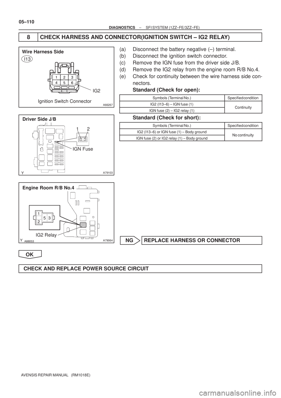
A66267
IG2 Wire Harness Side
Ignition Switch Connector
I13
A79103
Driver Side J/B
IGN Fuse12
������A79064
Engine Room R/B No.4
IG2 Relay
05±110
± DIAGNOSTICSSFI SYSTEM (1ZZ±FE/3ZZ±FE)
AVENSIS REPAIR MANUAL (RM1018E)
8 CHECK HARNESS AND CONNECTOR(IGNITION SWITCH ± IG2 RELAY)
(a) Disconnect the battery negative (±) terminal.
(b) Disconnect the ignition switch connector.
(c) Remove the IGN fuse from the driver side J/B.
(d) Remove the IG2 relay from the engine room R/B No.4.
(e) Check for continuity between the wire harness side con-
nectors.
Standard (Check for open):
Symbols (Terminal No.)Specified condition
IG2 (I13±6) ± IGN fuse (1)ContinuityIGN fuse (2) ± IG2 relay (1)Continuity
Standard (Check for short):
Symbols (Terminal No.)Specified condition
IG2 (I13±6) or IGN fuse (1) ± Body groundNo continuityIGN fuse (2) or IG2 relay (1) ± Body groundNo continuity
NG REPLACE HARNESS OR CONNECTOR
OK
CHECK AND REPLACE POWER SOURCE CIRCUIT
Page 270 of 5135
GND (±)
ISC valve Connector
Wire Harness Side
I10
±
DIAGNOSTICS SFI SYSTEM(1ZZ±FE/3ZZ±FE)
05±101
AVENSIS REPAIR MANUAL (RM1018E)
1PERFORM ACTIVE TEST USING HAND±HELD TESTER(C")
123
A66264VISC (+)GND (±)
ISC valve Connector
Wire Harness Side
I10
±
DIAGNOSTICS SFI SYSTEM(1ZZ±FE/3ZZ±FE)
05±101
AVENSIS REPAIR MANUAL (RM1018E)
1PERFORM ACTIVE TEST USING HAND±HELD TESTER(CHECK ISC VALVE
OPERATION)
(a)Warm up the engine to the normal operating temperature.
(b)Switch off all the accessories.
(c)Switch off the A/C.
(d)Shift the lever to the neutral position.
(e)Connect the hand±held tester to the DLC3 on the vehicle.
(f)Select the item ºDIAGNOSIS / OBD/MOBD / ACTIVE TEST / ISC DUTY RATIOº.
(g)Check that the engine RPM varies when changing the ISC duty ratio.
Engine RPM:
Engine RPM fluctuates ups and downs in respose to the ISC duty ratio var\
iation.
OKCHECK FOR INTERMITTENT PROBLEMS (See page 05±5)
NG
2 CHECK HARNESS AND CONNECTOR
(a) Disconnect the ISC valve connector.
(b) Turn the ignition switch ON.
(c) Measure the voltage between the terminals of the ISC valve wire harness side connector.
Standard:
Symbols (Terminal No.)Specified condition
VISC (I10±2) ± GND (I10±3)9 to 14 V
NG REPAIR OR REPLACE HARNESS OR CONNECTOR
OK
Page 273 of 5135
E1 (±)ECM Connector
E12 E10
A62954
Turn Wheel
4.5±5.5V
0V
±
DIAGNOSTICS SFI SYSTEM(1ZZ±FE/3ZZ±FE)
05±99
AVENSIS REPAIR MANUAL (RM1018E)
INSPECTION PROCEDURE
HINT:
Read freeze fra")
A18294
SPD (+)E1 (±)ECM Connector
E12 E10
A62954
Turn Wheel
4.5±5.5V
0V
±
DIAGNOSTICS SFI SYSTEM(1ZZ±FE/3ZZ±FE)
05±99
AVENSIS REPAIR MANUAL (RM1018E)
INSPECTION PROCEDURE
HINT:
Read freeze frame data using \f���� ����\b�\f��\f�
� Freeze frame data records the engine conditions when
a malfunction is detected. When troubleshooting, it is useful for determi\
ning whether the vehicle was running
or stopped, the engine was warmed up or not, the air±fuel ratio was lea\
n or rich, etc. at the time of the mal-
function.
1CHECK OPERATION OF SPEEDOMETER(SPEEDOMETER OPERATION)
(a)Drive the vehicle and check that the operation of the speedometer in the\
combination meter is normal.
HINT:
The vehicle speed sensor is operating normally if the speedometer display i\
s normal.
NGCHECK SPEEDOMETER CIRCUIT
OK
2INSPECT ECM(CHECK VOLTAGE)
(a)Shift the lever to the neutral position.
(b)Jack up the vehicle.
(c)Turn the ignition switch ON.
(d)Measure the voltage between the terminals of the E10 and E12 ECM connectors as the wheel is turned slowly.
Standard:
Symbols (Terminal No.)Specified condition
SPD (E10±17) ± E1 (E12±7)Generated intermittently
HINT:
The output voltage should fluctuate up and down similarly to the
diagram on the left when the wheel is turned slowly.
NGREPAIR OR REPLACE HARNESS AND CONNECTOR
OK
CHECK AND REPLACE ECM (See page 01±32)
Page 275 of 5135
 ECM Connector
E13
EVP1 (+)
±
DIAGNOSTICS SFI SYSTEM(1ZZ±FE/3ZZ±FE)
05±95
AVENSIS REPAIR MANUAL (RM1018E)
1PERFORM ACTIVE TEST BY HAND±HELD TEST")
A79090VSV is ONVSV is OFF
E
F E
F
A18294
E01 (±) ECM Connector
E13
EVP1 (+)
±
DIAGNOSTICS SFI SYSTEM(1ZZ±FE/3ZZ±FE)
05±95
AVENSIS REPAIR MANUAL (RM1018E)
1PERFORM ACTIVE TEST BY HAND±HELD TESTER(VSV FOR EVAP)
(a)Select the ACTIVE TEST mode on the hand±held tester.
(b)Disconnect the vacuum hose from the VSV for EVAP.
(c)Start the engine.
(d)When the VSV for EVAP is operated by the hand±held
tester, apply the disconnected hose to your finger to
check the suction.
Result:
VSV is ON: Disconnected port sucks.
VSV is OFF: Disconnected port does not suck.
OKCHECK FOR INTERMITTENT PROBLEMS
NG
2INSPECT ECM(CHECK VOLTAGE)
(a)Turn the ignition switch ON.
(b)Measure the voltage between the terminals of the E13 ECM connector.
Standard:
Symbols (Terminal No.)Specified condition
EVP1 (E13±12) ± E01 (E13±7)8 to 14 V
OKCHECK AND REPLACE ECM
NG
3INSPECT VACUUM SWITCHING VALVE ASSY NO.1
NGREPLACE VACUUM SWITCHING VALVE ASSY NO.1
OK
4CHECK FUSE(EFI No.2) (See page 05±45)
NG CHECK FOR SHORT IN ALL HARNESS AND COMPONENTS CONNECTED FUSE
OK
Page 277 of 5135

A66053
Engine Room R/B No.4EFI Relay
�����
�
A79070
Engine Room R/B No.4EFI No.2 Fuse
1
2
��\b��A52933
Wire Harness Side
Vacuum Switching Valve Connector
V5
±
DIAGNOSTICS SFI SYSTEM(1ZZ±FE/3ZZ±FE)
05±97
AVENSIS REPAIR MANUAL (RM1018E)
6CHECK HARNESS AND CONNECTOR(EFI RELAY ± VSV FOR EVAP)
(a)Remove the EFI relay from the engine room R/B No.4.
(b)Remove the EFI No.2 fuse from the engine room R/B
No.4.
(c)Disconnect the VSV connector.
(d)Check for continuity between the wire harness side con- nectors.
Standard (Check for open):
Symbols (Terminal No.)Specified condition
EFI relay (3) ± EFI No.2 fuse (1)ContinuityEFI No.2 fuse (2) ± VSV (V5±1)Continuity
Standard (Check for short):
Symbols (Terminal No.)Specified condition
EFI relay (3) or EFI No.2 fuse (1) ± Body groundNocontinuityEFI No.2 fuse (2) or VSV (V5±1) ± Body groundNo continuity
NOTICE:
Do not insert the tester leads hard in the procedure (c), the
holder may be damaged.
NGREPAIR OR REPLACE HARNESS OR CONNECTOR
OK
CHECK FOR ECM POWER SOURCE CIRCUIT (See page 05±124)

AVENSIS REPAIR MANUAL (RM1018E)
Standard (Check for short):
Symbols (Terminal No.)Specified condition
IGT (I1±3) or IGT1 (E13±8) ± Body")