Page 246 of 5135
A75744
ECM
Engine Coolant
Temperature Sensor
A65743ECM Connector
E13
±
DIAGNOSTICS SFI SYSTEM(1ZZ±FE/3ZZ±FE)
05±37
AVENSIS REPAIR MANUAL (RM1018E)
5READ VALUE OF HAND±HELD TESTER(CHECK FOR SHORT IN ECM)
(a)Disconnect the E13 ECM connector.
(b)Disconnect the engine coolant temperature sensor con-
nector.
(c)Turn the ignition switch ON.
(d)Select the item ºDIAGNOSIS / OBD/MOBD / DATA LIST / ALL / COOLANT TEMPº and read its value displayed on
the hand±held tester.
Temperature: ±40 �C (±40 �F)
OKREPAIR OR REPLACE HARNESS OR CONNECTOR
NG
CHECK AND REPLACE ECM (See page 01±32)
Page 248 of 5135

4
5 G±R
BR E2
THA ECM
20
E13
E13 28 5V
R
THA
E2
±
DIAGNOSTICS SFI SYSTEM(1ZZ±FE/3ZZ±FE)
05±31
AVENSIS REPAIR MANUAL (RM1018E)
WI")
A72925
A6
Intake Air Temp. Sensor
(built in Mass Air Flow Meter)
4
5 G±R
BR E2
THA ECM
20
E13
E13 28 5V
R
THA
E2
±
DIAGNOSTICS SFI SYSTEM(1ZZ±FE/3ZZ±FE)
05±31
AVENSIS REPAIR MANUAL (RM1018E)
WIRING DIAGRAM
INSPECTION PROCEDURE
HINT:
�Read freeze frame data using \f���� ����\b�\f��\f�
� Freeze frame data records the engine conditions
when a malfunction is detected. When troubleshooting, it is useful for d\
etermining whether the vehicle
was running or stopped, the engine was warmed up or not, the air±fuel ra\
tio was lean or rich, etc. at
the time of the malfunction.
�If different DTCs that are related to a different system are output simultaneously while terminal E2 is
used as a ground terminal, terminal E2 may be open.
1READ VALUE OF HAND±HELD TESTER(INTAKE AIR TEMPERATURE)
(a)Connect the hand±held tester to the DLC3.
(b)Turn the ignition switch ON.
(c)Select the item ºDIAGNOSIS / OBD/MOBD / DATA LIST / ALL / INTAKE AIRº and read its value dis- played on the hand±held tester.
Temperature: The same as actual intake air temperature
Result:
Temperature DisplayedProceed to
±40 �C (±40 �F)A
140 �C (284 �F) or moreB
OK (Same as present temperature)C
HINT:
�If there is an open circuit, the hand±held tester indicates ±40
C (±40
F).
�If there is a short circuit, the hand±held tester indicates 140
C (284
F) or more.
BGo to step 4
CCHECK FOR INTERMITTENT PROBLEMS (See Page 05±5)
A
Page 252 of 5135
A66054
Engine Room R/B No.1EFI Fuse
A18294
BATT (+)E1 (±)
ECM Connector
E9E12
05±120
±
DIAGNOSTICS SFI SYSTEM(1ZZ±FE/3ZZ±FE)
AVENSIS REPAIR MANUAL (RM1018E)
1CHECK FUSE(EFI FUSE)
(a)Remove the EFI fuse from the engine room R/B No.1.
(b)Check for continuity in the EFI fuse. Standard: Continuity
NGCHECK FOR SHORT IN ALL HARNESSES AND COMPONENTS CONNECTED FUSE
OK
2INSPECT ECM(CHECK VOLTAGE)
(a)Turn the ignition switch ON.
(b)Measure the voltage between the terminals of the E9 and E12 ECM connector.
Standard:
Symbols (Terminal No.)Specified condition
BATT (E9±3) ± E1 (E12±7)8 to 14 V
OKCHECK AND REPLACE ECM (See page 01±32)
NG
Page 253 of 5135
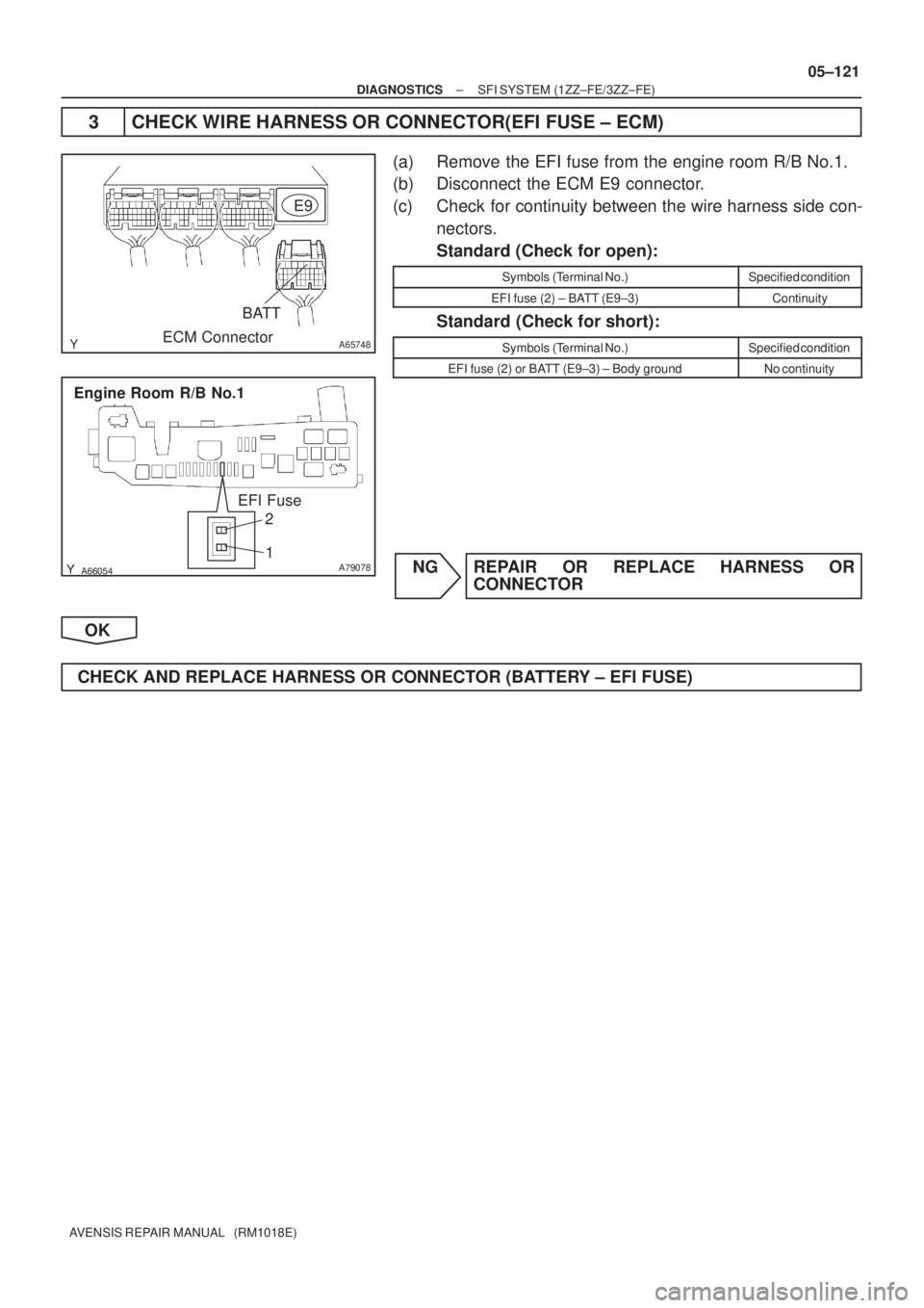
A65748
E9
ECM Connector
BATT
������A79078
Engine Room R/B No.1
EFI Fuse
2
1
± DIAGNOSTICSSFI SYSTEM (1ZZ±FE/3ZZ±FE)
05±121
AVENSIS REPAIR MANUAL (RM1018E)
3 CHECK WIRE HARNESS OR CONNECTOR(EFI FUSE ± ECM)
(a) Remove the EFI fuse from the engine room R/B No.1.
(b) Disconnect the ECM E9 connector.
(c) Check for continuity between the wire harness side con-
nectors.
Standard (Check for open):
Symbols (Terminal No.)Specified condition
EFI fuse (2) ± BATT (E9±3)Continuity
Standard (Check for short):
Symbols (Terminal No.)Specified condition
EFI fuse (2) or BATT (E9±3) ± Body groundNo continuity
NG REPAIR OR REPLACE HARNESS OR
CONNECTOR
OK
CHECK AND REPLACE HARNESS OR CONNECTOR (BATTERY ± EFI FUSE)
Page 256 of 5135

05±117
AVENSIS REPAIR MANUAL (RM1018E)
INSPECTION PROCEDURE
HINT:
Read freeze frame data using ��� �� ������ �����
� Freeze frame data records the engine")
± DIAGNOSTICSSFI SYSTEM (1ZZ±FE/3ZZ±FE)
05±117
AVENSIS REPAIR MANUAL (RM1018E)
INSPECTION PROCEDURE
HINT:
Read freeze frame data using ��� �� ������ �����
� Freeze frame data records the engine conditions when
a malfunction is detected. When troubleshooting, it is useful for determining whether the vehicle was running
or stopped, the engine was warmed up or not, the air±fuel ratio was lean or rich, etc. at the time of the mal-
function.
1 CHECK OPERATION OF STOP LIGHT
(a) Check if the stop lights go on and off normally when the brake pedal is depressed and released.
NG REPAIR OR REPLACE STOP LAMP SWITCH
CIRCUIT
OK
2 READ VALUE OF HAND±HELD TESTER
(a) Connect the hand±held tester to the DLC3.
(b) Select the item ºDIAGNOSIS / OBD/MOBD / DATA LIST / ALL / STOP LIGHT SWº and read its value
displayed the hand±held tester.
(c) Turn the ignition switch ON and push the hand±held tester main switch ON.
(d) Read the STP signal on the hand±held tester.
Result:
Brake PedalSTP Signal
DepressedON
ReleasedOFF
OK CHECK FOR INTERMITTENT PROBLEMS
NG
Page 258 of 5135

AVENSIS REPAIR MANUAL (RM1018E)
DTCP1349VVT SYSTEM MALFUNCT")
A63991
ECM
C2
Camshaft Timing
Oil Control Valve
2
1
Y±B
W±G
OCV+
OCV±
15
14
E13
E13
05±112
±
DIAGNOSTICS SFI SYSTEM(1ZZ±FE/3ZZ±FE)
AVENSIS REPAIR MANUAL (RM1018E)
DTCP1349VVT SYSTEM MALFUNCTION (BANK 1)
CIRCUIT DESCRIPTION
VVT system controls the intake valve timing to proper timing in response to\
driving condition.
The ECM controls the oil control valve (OCV) to make the intake valve timing properly, oil pressure regulated
by the OCV is supplied to the valiable valve timing (VVT) controller, and then the VVT controller changes
relative position between the camshaft and the crankshaft.
DTC No.DTC Detecting ConditionTrouble Area
P1349
Condition (a) or (b) continues with engine speed at 400 to
4,000 rpm after the engine is warmed up
(a)Valve timing does not change from the current valve timing
(b)Current valve timing is fixed� Valve timing
� OCV
� VVT controller assembly
� ECM
WIRING DIAGRAM
INSPECTION PROCEDURE
HINT:
Read freeze frame data using \f���� ����\b�\f��\f�
� Freeze frame data records the engine conditions when
a malfunction is detected. When troubleshooting, it is useful for determi\
ning whether the vehicle was running
or stopped, the engine was warmed up or not, the air±fuel ratio was lea\
n or rich, etc. at the time of the mal-
function.
1CHECK VALVE TIMING (See page 14±49)
NGADJUST VALVE TIMING(See page 14±49)
OK
05C6F±01
Page 259 of 5135
(A)(A)
±
DIAGNOSTICS SFI SYSTEM(1ZZ±FE/3ZZ±FE)
05±113
AVENSIS REPAIR MANUAL (RM1018E)
2P")
A18294
OCV+OCV±
ECM Connector
E13
A58701A58701
OCV Signal Waveform1 m sec./Division 5 V/
Division
GND
(A)(A)(A)
±
DIAGNOSTICS SFI SYSTEM(1ZZ±FE/3ZZ±FE)
05±113
AVENSIS REPAIR MANUAL (RM1018E)
2PERFORM ACTIVE TEST BY HAND±HELD TESTER(OPERATE OF OCV)
(a)Start the engine and warm it up.
(b)Connect the hand±held tester and select VVT from the ACTIVE TEST menu\
.
(c)Check the engine speed while operating the OCV by the hand±held teste\
r.
OCV is OFF: Normal engine speed
OCV is ON: Rough idle or engine stall
HINT:
DTC P1349 is also output when a foreign object is detected in some parts\
of the system in engine oil, and
then the system returns to normal in a short time. There is also no problem \
on the VVT as the oil filter should
catch the foreign object in engine oil.
OKVVT SYSTEM OK
NG
3INSPECT ECM(CHECK VOLTAGE)
(a)Turn the ignition switch ON.
(b)Check the waveform between terminals OCV+ and OCV± of the E13 ECM connector.
HINT:
�The correct waveform is as shown on the left.
�The waveform frequency (A) becomes longer as the en-
gine speed becomes higher.
NGCHECK AND REPLACE ECM (See page 01±32)
OK
4INSPECT CAMSHAFT TIMING GEAR ASSY (See page14±64)
NG REPLACE VVT CONTROLLER ASSEMBLY, AND THEN GO TO NEXT STEP
OK
Page 260 of 5135
05±114
±
DIAGNOSTICS SFI SYSTEM(1ZZ±FE/3ZZ±FE)
AVENSIS REPAIR MANUAL (RM1018E)
5INSPECT CAMSHAFT TIMING OIL CONTROL VALVE ASSY (See page 10±3)
NGREPLACE CAMSHAFT TIMING OIL CONTROL VALVE ASSEMBLY, AND THEN GO TO NEXT
STEP
OK
6CHECK OIL CONTROL VALVE FILTER(CHECK BLOCKAGE)
NGREPAIR OR REPLACE OIL CONTROL VALVE FILTER
OK
7PERFORM SIMULATION TEST(DTC CHECK)
(a)Clear the DTC (See page 05±5).
(b)Perform the simulation test.
(c)Check whether or not DTC P1349 is stored (See page 05±5). Result:
DTCProceed to
ºP1349º is output.A
ºP1349º is not output.B
HINT:
DTC P1349 is also output when a foreign object is detected in some parts\
of the system in engine oil, and
then the system returns to normal in a short time. There is also no problem \
on the VVT as the oil filter should
catch the foreign object in the engine oil.
BVVT SYSTEM OK
A
CHECK AND REPLACE ECM (See page 01±32)

05±37
AVENSIS REPAIR MANUAL (RM1018E)
5READ VALUE OF HAND±HELD TESTER(CHECK FOR SHO")
E1 (±)
ECM Connector
E9E12
05±120
±
DIAGNOSTICS SFI SYSTEM(1ZZ±FE/3ZZ±FE)
AVENSIS REPAIR MANUAL (RM1018E)
1CHECK FUSE(EFI FUSE)
(a)Remove the")

AVENSIS REPAIR MANUAL (RM1018E)
5INSPECT CAMSHAFT TIMING OIL CONTROL VALVE ASSY (See page 10±3)
NGREPLACE CAMSHAFT TIMING OIL CONTROL VALVE ASSEMB")