Page 378 of 5135
A76869
Engine Room R/B No.1
Engine Room J/B No.1
EFI
12
1 1A1
B±G
4A
4B 11
Engine
Room J/B No.4
B±G
FL MAIN
Battery
EFBR B±Y
IE3
IO1 77
(LHD)(RHD)B±Y3
E9 BATTECM
E1 7
E12
A66054
Engine Room R/B No.1
EFI Fuse
05±262
± DIAGNOSTICSSFI SYSTEM (1AZ±FE)
AVENSIS REPAIR MANUAL (RM1018E)
ECM BACK±UP POWER SOURCE CIRCUIT
CIRCUIT DESCRIPTION
While the ignition switch is OFF, the battery positive voltage is supplied to terminal BATT of the ECM for the
DTCs memory and air±fuel ratio adaptive control value memory, etc.
WIRING DIAGRAM
INSPECTION PROCEDURE
1 CHECK FUSE(EFI FUSE)
(a) Remove the EFI fuse from the engine room R/B No.1.
(b) Check for continuity in the EFI fuse.
Standard: Continuity
NG CHECK FOR SHORT IN ALL HARNESSES AND
COMPONENTS CONNECTED FUSE
OK
05C78±01
Page 379 of 5135
E1 (±)
ECM Connector
E9E12
A65748
E9
ECM Connector
BATT
������A79078
Engine Room R/B No.1 EFI Fuse2
1
±
DIAGNOSTICS SFI SYSTEM(1AZ±FE)
05±263
AVENSIS REPAIR MANUAL (RM1018E)
2INSP")
A18294
BATT (+)E1 (±)
ECM Connector
E9E12
A65748
E9
ECM Connector
BATT
������A79078
Engine Room R/B No.1 EFI Fuse2
1
±
DIAGNOSTICS SFI SYSTEM(1AZ±FE)
05±263
AVENSIS REPAIR MANUAL (RM1018E)
2INSPECT ECM(BATT VOLTAGE)
(a)Turn the ignition switch ON.
(b)Measure the voltage between the terminals of the E9 and
E12 ECM connector.
Standard:
Symbols (Terminal No.)Specified condition
BATT (E9±3) ± E1 (E12±7)8 to 14 V
OKCHECK AND REPLACE ECM (See page 01±32)
NG
3 CHECK HARNESS AND CONNECTOR(ECM ± EFI FUSE, EFI FUSE ± BATTERY)
(a) Check the harness and connector between the EFI fuse and ECM.
(1) Remove the EFI fuse from the engine room R/B.
(2) Disconnect the E9 ECM connector.
(3) Check for continuity between the wire harness sideconnectors.
Standard (Check for open):
Symbols (Terminal No.)Specified condition
EFI fuse (2) ± BATT (E9±3)Continuity
Standard (Check for short):
Symbols (Terminal No.)Specified condition
EFI fuse (2) or BATT (E9±3) ± Body groundNo continuity
(b) Check the harness and connector between the EFI fuse and battery.
(1) Remove the EFI fuse from the engine room R/B.
(2) Disconnect the battery positive terminal.
(3) Check for continuity between the wire harness sideconnectors.
Standard (Check for open):
Symbols (Terminal No.)Specified condition
Battery positive terminal ± EFI fuse (1)Continuity
Standard (Check for short):
Symbols (Terminal No.)Specified condition
Battery positive terminal or EFI fuse (1) ± Body groundNo continuity
NG REPAIR OR REPLACE HARNESS OR CONNECTOR
OK
CHECK AND REPLACE ENGINE ROOM RELAY BLOCK
Page 383 of 5135
A66054
Engine Room R/B No.1
EFI Fuse
B16200
������
� �
A79065
Engine Room R/B No.4
EFI No.1 Fuse
05±260
± DIAGNOSTICSSFI SYSTEM (1AZ±FE)
AVENSIS REPAIR MANUAL (RM1018E)
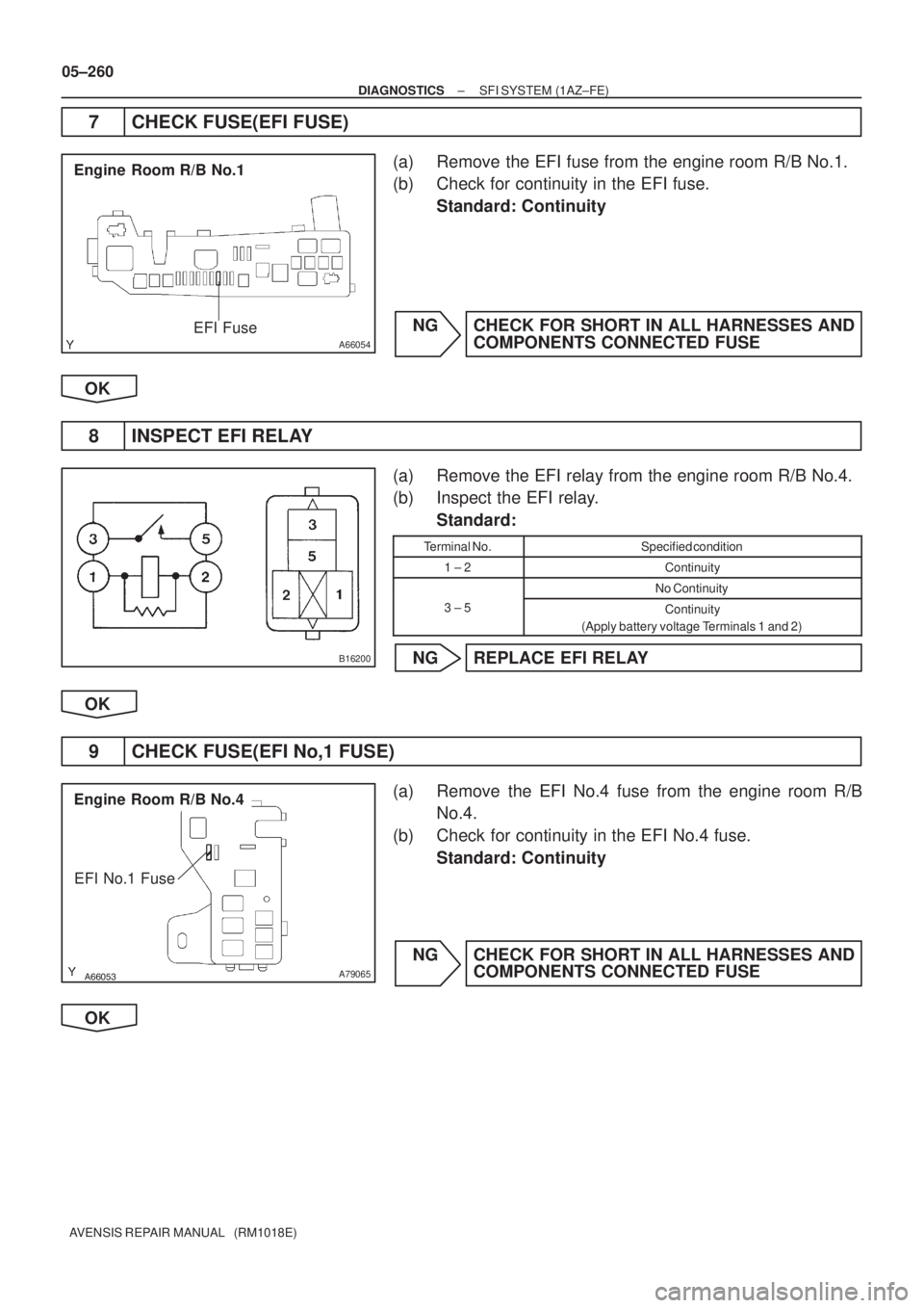
7 CHECK FUSE(EFI FUSE)
(a) Remove the EFI fuse from the engine room R/B No.1.
(b) Check for continuity in the EFI fuse.
Standard: Continuity
NG CHECK FOR SHORT IN ALL HARNESSES AND
COMPONENTS CONNECTED FUSE
OK
8 INSPECT EFI RELAY
(a) Remove the EFI relay from the engine room R/B No.4.
(b) Inspect the EFI relay.
Standard:
Terminal No.Specified condition
1 ± 2Continuity
No Continuity
3 ± 5Continuity
(Apply battery voltage Terminals 1 and 2)
NG REPLACE EFI RELAY
OK
9 CHECK FUSE(EFI No,1 FUSE)
(a) Remove the EFI No.4 fuse from the engine room R/B
No.4.
(b) Check for continuity in the EFI No.4 fuse.
Standard: Continuity
NG CHECK FOR SHORT IN ALL HARNESSES AND
COMPONENTS CONNECTED FUSE
OK
Page 384 of 5135

05±261
AVENSIS REPAIR MANUAL (RM1018E")
A66053
Engine Room R/B No.4
EFI Relay
������
�
A79066
Engine Room R/B No.4
EFI No.1 Fuse
1
2
A65748
MREL
E9
ECM Connector
+B
± DIAGNOSTICSSFI SYSTEM (1AZ±FE)
05±261
AVENSIS REPAIR MANUAL (RM1018E)
10 CHECK HARNESS AND CONNECTOR(EFI RELAY ± ECM, EFI RELAY ± BODY
GROUND)
(a) Check the harness and connector between the EFI relay
and ECM connector.
(1) Remove the EFI relay from the engine room R/B
No.4.
(2) Remove the EFI No.1 fuse from the engine room
R/B No.4.
(3) Disconnect the E9 ECM connector.
(4) Check for continuity between the wire harness side
connectors.
Standard (Check for open):
Symbols (Terminal No.)Specified condition
EFI relay (1) ± MREL (E9±8)
EFI relay (3) ± EFI No.1 fuse (1)Continuity
EFI No.1 fuse (2) ± +B (E9±1)
y
Standard (Check for short):
Symbols (Terminal No.)Specified condition
EFI relay (1) or MREL (E9±8) ± Body ground
EFI relay (3) or EFI No.1 fuse (1) ± Body groundNo continuity
EFI No.1 fuse (2) or +B (E9±1) ± Body ground
y
(b) Check the harness and connector between the EFI relay
and body ground.
(1) Remove the EFI relay from the engine room J/B
No.4.
(2) Check for continuity between the wire harness side
connector and the body ground.
Standard (Check for open):
Symbols (Terminal No.)Specified condition
EFI relay (2) ± Body groundContinuity
OK REPAIR OR REPLACE HARNESS OR
CONNECTOR
NG
CHECK AND REPAIR HARNESS AND CONNECTOR (TERMINAL +B OF ECM ± BATTERY POS-
ITIVE TERMINAL)
Page 390 of 5135

Injection volume
Output voltage
Output voltage of heated oxygen
sensor (sensor 2)M")
+25 %
±12.5 %
More than 3.35 V
Less than 3.0 V
Case 1
Case 2
Case 3
Case 4
Output voltage of A/F sensor
(sensor 1)
Injection volume
Output voltage
Output voltage of heated oxygen
sensor (sensor 2)Mainly suspect
trouble area
OK
+25 %
±12.5 %
More than 3.35 V
Less than 3.0V
Injection volume
Output voltage
+25 %
±12.5 %
More than 0.55 V
Less than 0.4V
Injection volume
Output voltage
A/F sensor
(A/F sensor, heater, A/F sen-
sor circuit)
+25 %
±12.5 %
More than 0.55 V
Less than 0.4V
Injection volume
Output voltage
+25 %
±12.5 %
Injection volume
Output voltage
NG
+25 %
±12.5 %
Injection volume
Output voltage
NG
+25 %
±12.5 %
Injection volume
Output voltage
NG
+25 %
±12.5 %
Injection volume
Output voltage
NGExtremely rich or lean actual
air±fuel ratio
(Injector, fuel pressure, gas
leakage in exhaust system,
etc.) OK
OK
OK
No reaction
No reaction
No reaction No reaction
�
Heated oxygen sensor
(heated oxygen sensor,
heater, heated oxygen sensor
circuit)
± DIAGNOSTICSSFI SYSTEM (1AZ±FE)
05±253
AVENSIS REPAIR MANUAL (RM1018E)
The following procedure of A/F CONTROL enables the technician to check and graph voltage output of both
the A/F sensor and heated oxygen sensor.
For displaying the graph indication, enter ºACTIVE TEST/ A/F CONTROL/USER DATAº, then select ºAFS
B1S1 and O2S B1S2º or ºAFS B2S1 and O2S B2S2º by pressing ºYESº button and push ºENTERº button
before pressing ºF4º button.
HINT:
�If DTC ��������� ��������� ����
���� ��� ����� ��� ���� �� ��� ���� is displayed, check bank 1
sensor 1 circuit.
�If DTC ��������� ��������� ��������� ��� ����� ��� ��� �� ���
��� is displayed, check bank 2
sensor 1 circuit.
�Read freeze frame data using the hand±held tester. Freeze frame data records the engine conditions
when a malfunction is detected. When troubleshooting, it is useful for determining whether the vehicle
was running or stopped, the engine was warmed up or not, the air±fuel ratio was lean or rich, etc. at
the time of the malfunction.
Page 394 of 5135
±
DIAGNOSTICS SFI SYSTEM(1AZ±FE)
05±247
AVENSIS REPAIR MANUAL (RM1018E)
DTCP0606/89ECM/PCM PROCESSOR
CIRCUIT DESCRIPTION
DTC No.DTC Detection ConditionTrouble Area
P0606/89ECM inside error�ECM
INSPECTION PROCEDURE
HINT:
Read freeze frame data using \f���� ����\b�\f��\f�
� Freeze frame data records the engine conditions when
a malfunction is detected. When troubleshooting, it is useful for determi\
ning whether the vehicle was running
or stopped, the engine was warmed up or not, the air±fuel ratio was lea\
n or rich, etc. at the time of the mal-
function.
CHECK AND REPLACE ECM (See page 01±32)
05C75±01
Page 396 of 5135
GND (±)
ISC valve Connector
Wire Harness Side
I10
05±244
±
DIAGNOSTICS SFI SYSTEM(1AZ±FE)
AVENSIS REPAIR MANUAL (RM1018E)
When using hand±held tester:
1PERFORM ACTIVE TEST USIN")
123
A66264+B (+)GND (±)
ISC valve Connector
Wire Harness Side
I10
05±244
±
DIAGNOSTICS SFI SYSTEM(1AZ±FE)
AVENSIS REPAIR MANUAL (RM1018E)
When using hand±held tester:
1PERFORM ACTIVE TEST USING HAND±HELD TESTER(CHECK ISC VALVE OPERATION)
(a)Warm up the engine to the normal operating temperature.
(b)Switch off all the accessories.
(c)Switch off the A/C.
(d)Shift the lever to the neutral position.
(e)Connect the hand±held tester to the DLC3 on the vehicle.
(f)Select the item ºDIAGNOSIS / OBD/MOBD / ACTIVE TEST / ISC DUTY RATIOº.
(g)Check that the engine RPM varies when changing the ISC duty ratio.
Engine RPM:
Engine RPM fluctuates ups and downs in respose to the ISC duty ratio var\
iation.
OKCHECK FOR INTERMITTENT PROBLEMS(See page 05±149)
NG
2 CHECK HARNESS AND CONNECTOR
(a) Disconnect the ISC valve connector.
(b) Turn the ignition switch ON.
(c) Measure the voltage between the terminals of the ISC valve wire harness side connector.
Standard:
Symbols (Terminal No.)Specified condition
+B (I10±2) ± GND (I10±3)9 to 14 V
NG REPAIR OR REPLACE HARNESS OR CONNECTOR
OK
Page 400 of 5135
A76866
Combination MeterECM
C11 V±W
SPD
17
V±W E10
J/C
18H
J10
(LHD) J20
H
(RHD) H
J10
(LHD) J20
H
(RHD)
±
DIAGNOSTICS SFI SYSTEM(1AZ±FE)
05±241
AVENSIS REPAIR MANUAL (RM1018E)
WIRING DIAGRAM
INSPECTION PROCEDURE
HINT:
Read freeze frame data using \f���� ����\b�\f��\f�
� Freeze frame data records the engine conditions when
a malfunction is detected. When troubleshooting, it is useful for determi\
ning whether the vehicle was running
or stopped, the engine was warmed up or not, the air±fuel ratio was lea\
n or rich, etc. at the time of the mal-
function.
1CHECK OPERATION OF SPEEDOMETER
(a)Drive the vehicle and check that the operation of the speedometer in the\
combination meter is normal.
HINT:
The vehicle speed sensor is operating normally if the speedometer display i\
s normal.
NGCHECK SPEEDOMETER CIRCUIT(See page 05±1500)
OK
(RHD)B±Y3
E9 BATTECM
E1 7
E12
A66054
Engine Room R/B N")

 J20
H
(RHD) H
J10
(LHD) J20
H
(RHD)
±
DIAGNOSTICS SFI SYSTEM(1AZ±FE)
05±241
AVENSIS REPAIR MANUAL (RM1018E)
WIRING DIAGRAM
I")