Page 2635 of 5135

320W4±01
G24211
F42291
±
BRAKE BRAKE BOOSTER ASSY (RHD)
32±25
AVENSIS REPAIR MANUAL (RM1018E)
REPLACEMENT
NOTICE:
Do not adjust the brake booster push rod.
1. DRAIN BRAKE FLUID
NOTICE:
Wash the brake fluid off immediately if it adheres to any painted surface\
.
2.REMOVE BRAKE MASTER CYLINDER SUB±ASSY (See page 32±13)
(a) w/o VSC:
SST 09023±00100
(b) w/ VSC: SST 09023±38400
3.REMOVE CLUTCH MASTER CYLINDER ASSY (M/T TRANSAXLE) (See page 42±13) SST 09023±00100
4. REMOVE ENGINE ASSEMBLY WITH TRANSAXLE (1AZ±FSE ENGINE TYPE) (See page 14±204)
5. REMOVE ENGINE COVER NO.1
6.REMOVE IGNITION COIL ASSY (GASOLINE ENGINE TYPE) (See page 14±81)
7.REMOVE CYLINDER HEAD COVER SUB±ASSY (GASOLINE ENGINE TYPE) (See page 14±81)
8.REMOVE TIMING BELT NO.2 COVER (DIESEL ENGINE TYPE) (See page 14±307)
9.REMOVE CYLINDER HEAD COVER SUB±ASSY (DIESEL ENGINE TYPE) (See page 14±318)
10.REMOVE INJECTOR ASSY (DIESEL ENGINE TYPE) (See page 14±318)
11. REMOVE FRONT WHEEL RH
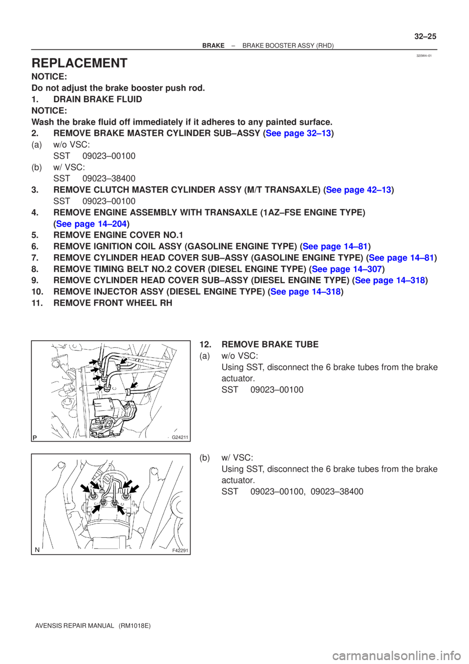
12. REMOVE BRAKE TUBE
(a) w/o VSC:Using SST, disconnect the 6 brake tubes from the brake
actuator.
SST 09023±00100
(b) w/ VSC: Using SST, disconnect the 6 brake tubes from the brake
actuator.
SST 09023±00100, 09023±38400
Page 2637 of 5135
F45361
F45362
F45367
F45363Vacuum tank
C81275
± BRAKEBRAKE BOOSTER ASSY (RHD)
32±27
AVENSIS REPAIR MANUAL (RM1018E)
(f) Using SST, disconnect the 3 brake tubes from the ways.
SST 09023±00100
(g) Disconnect the brake tube from the clamp and remove
the brake tubes.
(h) Disconnect the 3 brake tubes from the clamp and remove
the brake tubes.
13. REMOVE BRAKE BOOSTER ASSY
(a) Gasoline engine type:
Remove the 2 bolts and separate the vacuum pipe from
the body.
(b) Diesel engine type:
Remove the 2 bolts and remove the vacuum tank from the
body.
(c) Disconnect the vacuum hose from the brake booster
assy.
(d) Remove the engine under cover.
(e) Remove the 2 nuts from the engine mounting bracket RH.
(f) Remove the bolt from the rear engine mounting bracket.
(g) Remove the bolt and nut from the front engine mounting
bracket.
Page 2639 of 5135
C80805
C82119
C81275
C81274
F45367
± BRAKEBRAKE BOOSTER ASSY (RHD)
32±29
AVENSIS REPAIR MANUAL (RM1018E)
18. INSTALL BRAKE BOOSTER ASSY
(a) Install the clevis to the booster push rod.
(b) Install the brake booster assy with the 4 nuts.
Torque: 13 N�m (130 kgf�cm, 9 ft�lbf)
(c) Connect the vacuum hose to the check valve.
(d) Install the engine mounting bracket RH to the body with
the 3 bolts.
Torque: 52 N�m (530 kgf�cm, 39 ft�lbf)
(e) Install the bolt to the rear engine mounting bracket.
Torque: 87 N�m (887 kgf�cm, 64 ft�lbf)
(f) Install the bolt and nut to the front engine mounting brack-
et.
Torque: 52 N�m (530 kgf�cm, 39 ft�lbf)
(g) Install the 2 nuts to the engine mounting bracket RH.
Torque: 52 N�m (530 kgf�cm, 39 ft�lbf)
(h) Install the engine under cover.
(i) Connect the vacuum hose to the brake booster assy.
(j) Gasoline engine type:
Install the vacuum pipe with 2 bolts to the body.
Torque: 5.4 N�m (55 kgf�cm, 48 in.�lbf)
Page 2641 of 5135

F45057
w/o VSC:
w/ VSC:
To Master
Cylinder Rear
To
Master
Cylinder
Front
To Rear Wheel
RH
To Front Wheel LH
To Front Wheel RH
To Rear Wheel
LH
A
To
Master
Cylinder
FrontTo Master
Cylinder
Rear
To Rear
Wheel RH
To Front Wheel LHTo Front Wheel RH
To Rear
Wheel LH
AA
AA
BB
C80806
±
BRAKE BRAKE BOOSTER ASSY (RHD)
32±31
AVENSIS REPAIR MANUAL (RM1018E)
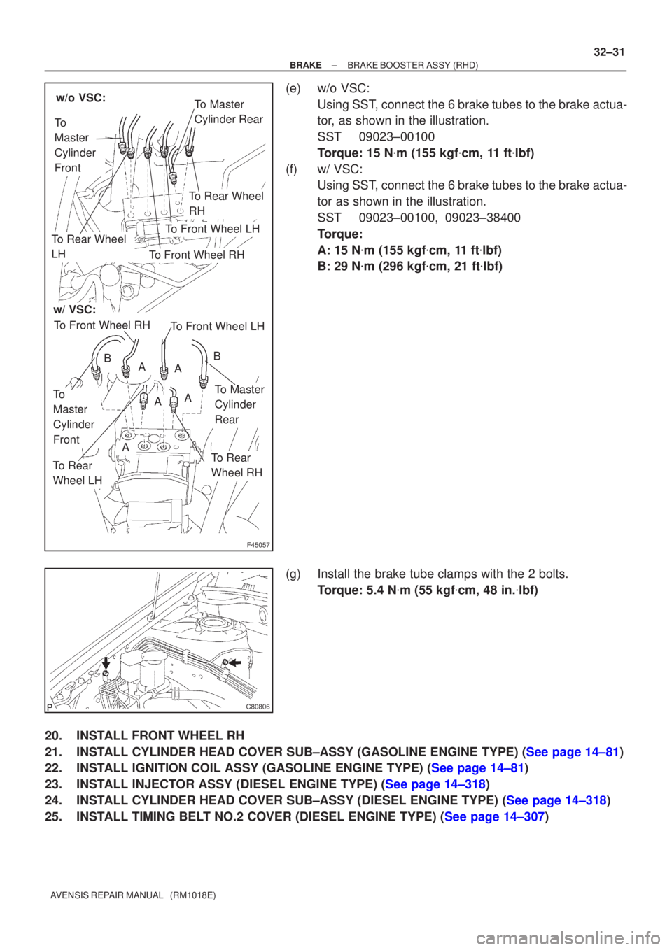
(e) w/o VSC:
Using SST, connect the 6 brake tubes to the brake actua-
tor, as shown in the illustration.
SST 09023±00100
Torque: 15 N �m (155 kgf �cm, 11 ft �lbf)
(f) w/ VSC: Using SST, connect the 6 brake tubes to the brake actua-
tor as shown in the illustration.
SST 09023±00100, 09023±38400
Torque:
A: 15 N �m (155 kgf �cm, 11 ft �lbf)
B: 29 N �m (296 kgf �cm, 21 ft �lbf)
(g) Install the brake tube clamps with the 2 bolts. Torque: 5.4 N �m (55 kgf �cm, 48 in. �lbf)
20. INSTALL FRONT WHEEL RH
21.INSTALL CYLINDER HEAD COVER SUB±ASSY (GASOLINE ENGINE TYPE) (See page 14±81)
22.INSTALL IGNITION COIL ASSY (GASOLINE ENGINE TYPE) (See page 14±81)
23.INSTALL INJECTOR ASSY (DIESEL ENGINE TYPE) (See page 14±318)
24.INSTALL CYLINDER HEAD COVER SUB±ASSY (DIESEL ENGINE TYPE) (See page 14±318)
25.INSTALL TIMING BELT NO.2 COVER (DIESEL ENGINE TYPE) (See page 14±307)
Page 2658 of 5135

330C7±01
F44818
33±10
±
PARKING BRAKE PARKING BRAKE CABLE ASSY NO.3
AVENSIS REPAIR MANUAL (RM1018E)
REPLACEMENT
HINT:
For parking brake cable assy No.2, perform the same procedure to the RH sid\
e.
1. REMOVE REAR WHEEL
2.DISCONNECT REAR DISC BRAKE CALIPER ASSY LH (See page 30±31)
3.REMOVE REAR DISC(See page 33±14)
4.REMOVE PARKING BRAKE ADJUSTER KIT (See page 33±14)
5.REMOVE PARKING BRAKE SHOE ADJUSTING SCREW SET(See page 33±14)
6.REMOVE PARKING BRAKE SHOE KIT (See page 33±14) SST 09718±00010
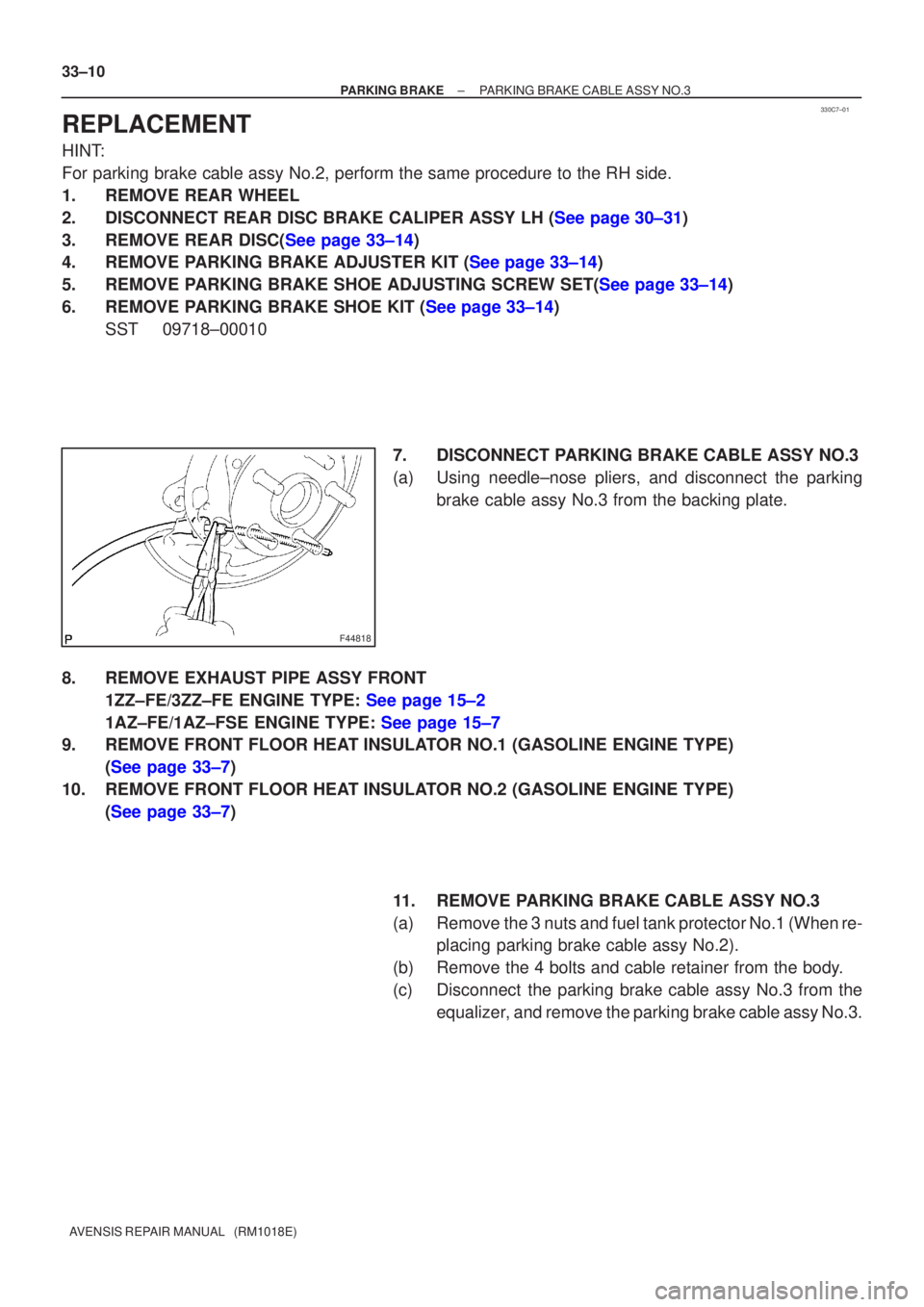
7. DISCONNECT PARKING BRAKE CABLE ASSY NO.3
(a) Using needle±nose pliers, and disconnect the parkingbrake cable assy No.3 from the backing plate.
8. REMOVE EXHAUST PIPE ASSY FRONT 1ZZ±FE/3ZZ±FE ENGINE TYPE: See page 15±2
1AZ±FE/1AZ±FSE ENGINE TYPE: See page 15±7
9. REMOVE FRONT FLOOR HEAT INSULATOR NO.1 (GASOLINE ENGINE TYPE)
(See page 33±7)
10. REMOVE FRONT FLOOR HEAT INSULATOR NO.2 (GASOLINE ENGINE TYPE) (See page 33±7)
11. REMOVE PARKING BRAKE CABLE ASSY NO.3
(a) Remove the 3 nuts and fuel tank protector No.1 (When re-placing parking brake cable assy No.2).
(b) Remove the 4 bolts and cable retainer from the body.
(c) Disconnect the parking brake cable assy No.3 from the equalizer, and remove the parking brake cable assy No.3.
Page 2659 of 5135
F44819
F44820
±
PARKING BRAKE PARKING BRAKE CABLE ASSY NO.3
33±11
AVENSIS REPAIR MANUAL (RM1018E)
12. INSTALL PARKING BRAKE CABLE ASSY NO.3
(a) Connect the parking brake cable assy No.3 to the equaliz-
er.
(b) Install the parking brake cable assy No.3 with the 4 bolts. Torque: 5.0 N �m (55 kgf �cm, 48 in. �lbf)
(c) Install the fuel tank protector No.1 and 3 nuts (When re- placing parking brake cable assy No.2).
Torque: 5.5 N �m (56 kgf �cm, 49 in. �lbf)
13. INSTALL FRONT FLOOR HEAT INSULATOR NO.2 (GASOLINE ENGINE TYPE) (See page 33±7)
14. INSTALL FRONT FLOOR HEAT INSULATOR NO.1 (GASOLINE ENGINE TYPE) (See page 33±7)
15. INSTALL EXHAUST PIPE ASSY FRONT 1ZZ±FE/3ZZ±FE ENGINE TYPE: See page 15±2
1AZ±FE/1AZ±FSE ENGINE TYPE: See page 15±7
16. CONNECT PARKING BRAKE CABLE ASSY NO.3
(a) Connect the parking brake cable assy No.3 to the backingplate.
Page 2661 of 5135
3306C±05
F44817
Parking Brake Cable Assy No.2
Parking Brake Cable Assy No.3
Equalizer
Front Floor Heat
Insulator No.1Front Floor Heat Insulator No.2Fuel Tank Protector No.1
Exhaust Pipe SupportCable
Retainer
N�m (kgf�cm, ft�lbf) : Specified torqueFront Floor Panel Brace Gasoline Engine Type:Gasoline Engine Type:
5.5 (56, 49 in.�lbf)
5.0 (51, 44 in.�lbf)
5.0 (51, 44 in.�lbf)
5.0 (51, 44 in.�lbf)
5.0 (51, 44 in.�lbf)
43 (440, 32)
5.5 (56, 49 in.�lbf)
Parking Brake Cable No.2 Clamp
Parking Brake Cable
No.2 Clamp
5.0 (51, 44 in.�lbf)
43 (440, 32)30 (302, 21)
Exhaust Pipe Assy Front
Exhaust Pipe Support
43 (440, 32)
5.5 (56, 49 in.�lbf)
5.5 (56, 49 in.�lbf)
5.0 (51, 44 in.�lbf)
± PARKING BRAKEPARKING BRAKE CABLE ASSY NO.3
33±9
AVENSIS REPAIR MANUAL (RM1018E)
PARKING BRAKE CABLE ASSY NO.3
COMPONENTS
Page 2662 of 5135

3306B±03
F44815
F44816
±
PARKING BRAKE PARKING BRAKE CABLE ASSY NO.1
33±7
AVENSIS REPAIR MANUAL (RM1018E)
REPLACEMENT
1. REMOVE SHIFT LEVER KNOB SUB±ASSY (M/T TRANSAXLE)
(See page 41±11)
2.REMOVE CONSOLE PANEL SUB±ASSY UPPER (See page 71±11)
3.REMOVE CONSOLE PANEL SUB±ASSY LOWER (See page 71±11)
4.REMOVE CONSOLE BOX ASSY RR (See page 71±11)
5.REMOVE PARKING BRAKE LEVER SUB±ASSY (See page 33±4)
6. REMOVE EXHAUST PIPE ASSY FRONT 1ZZ±FE/3ZZ±FE ENGINE TYPE: See page 15±2
1AZ±FE/1AZ±FSE ENGINE TYPE: See page 15±7
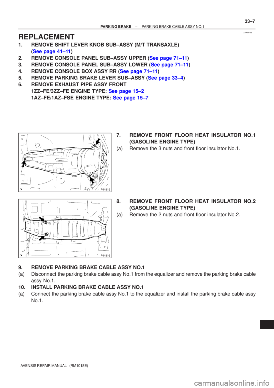
7. REMOVE FRONT FLOOR HEAT INSULATOR NO.1(GASOLINE ENGINE TYPE)
(a) Remove the 3 nuts and front floor insulator No.1.
8. REMOVE FRONT FLOOR HEAT INSULATOR NO.2 (GASOLINE ENGINE TYPE)
(a) Remove the 2 nuts and front floor insulator No.2.
9. REMOVE PARKING BRAKE CABLE ASSY NO.1
(a) Disconnect the parking brake cable assy No.1 from the equalizer and remove the parking brake cable assy No.1.
10. INSTALL PARKING BRAKE CABLE ASSY NO.1
(a) Connect the parking brake cable assy No.1 to the equalizer and install the park\
ing brake cable assy No.1.