Page 2663 of 5135
F44816
F44815
33±8
±
PARKING BRAKE PARKING BRAKE CABLE ASSY NO.1
AVENSIS REPAIR MANUAL (RM1018E)
11. INSTALL FRONT FLOOR HEAT INSULATOR NO.2 (GASOLINE ENGINE TYPE)
(a) Install the front floor insulator No.2 with the 2 nuts.
Torque: 5.5 N �m (56 kgf �cm, 49 in. �lbf)
12. .INSTALL FRONT FLOOR HEAT INSULATOR NO.1 (GASOLINE ENGINE TYPE)
(a) Install the front floor insulator No.1 with the 3 nuts. Torque: 5.5 N �m (56 kgf �cm, 49 in. �lbf)
13. INSTALL EXHAUST PIPE ASSY FRONT 1ZZ±FE/3ZZ±FE ENGINE TYPE: See page 15±2
1AZ±FE/1AZ±FSE ENGINE TYPE: See page 15±7
14.INSTALL PARKING BRAKE LEVER SUB±ASSY (See page 33±4)
15.INSPECT PARKING BRAKE LEVER TRAVEL (See page 33±2)
16.ADJUST PARKING BRAKE LEVER TRAVEL (See page 33±2)
Page 2664 of 5135
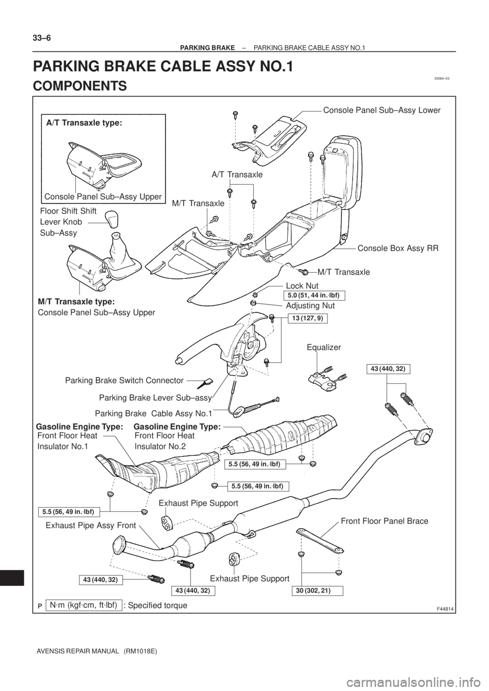
3306A±03
F44814
Parking Brake Lever Sub±assy Parking Brake Switch ConnectorLock Nut
5.0 (51, 44 in.�lbf)
Adjusting Nut
Parking Brake Cable Assy No.1Equalizer
Front Floor Heat
Insulator No.1Front Floor Heat
Insulator No.2
Exhaust Pipe Assy FrontExhaust Pipe Support
Exhaust Pipe Support
N�m (kgf�cm, ft�lbf)
: Specified torqueFront Floor Panel Brace Gasoline Engine Type: Gasoline Engine Type:
5.5 (56, 49 in.�lbf)
5.5 (56, 49 in.�lbf)
5.5 (56, 49 in.�lbf)
13 (127, 9)
43 (440, 32)
A/T Transaxle type:
Console Panel Sub±Assy Upper
M/T Transaxle type:
Console Panel Sub±Assy UpperFloor Shift Shift
Lever Knob
Sub±Assy
Console Box Assy RR
Console Panel Sub±Assy Lower
43 (440, 32)
A/T Transaxle
M/T Transaxle
M/T Transaxle
43 (440, 32)30 (302, 21)
33±6
± PARKING BRAKEPARKING BRAKE CABLE ASSY NO.1
AVENSIS REPAIR MANUAL (RM1018E)
PARKING BRAKE CABLE ASSY NO.1
COMPONENTS
Page 2675 of 5135

AVENSIS REPAIR MANUAL (RM1018E)
TRANSMISSION WIRE (U241E)
REPLACEMENT
1. REMOVE ENGINE UNDER C")
400DD±02
C83111
AT0103
D25591
C50009
40±52
± AUTOMATIC TRANSMISSION / TRANSTRANSMISSION WIRE (U241E)
AVENSIS REPAIR MANUAL (RM1018E)
TRANSMISSION WIRE (U241E)
REPLACEMENT
1. REMOVE ENGINE UNDER COVER LH
2. DRAIN AUTOMATIC TRANSAXLE FLUID
(a) Remove the drain plug, gasket and drain ATF.
(b) Install a new gasket and the drain plug.
Torque: 49 N�m (500 kgf�cm, 36 ft�lbf)
3. REMOVE AUTOMATIC TRANSAXLE OIL PAN
SUB±ASSY
(a) Remove the 18 bolts, oil pan and gasket.
NOTICE:
Some fluid will remain in the oil pan. Remove all of the oil
pan bolts, and carefully remove the oil pan assembly. Dis-
card the gasket.
(b) Remove the 2 magnets from the oil pan.
(c) Examine the particles in the oil pan.
(1) Remove the magnets and use them to collect any
steel chips. Look at the chips and particles in the oil
pan and on the magnet carefully to see the type of
wear which might be found in the tranaxle.
Steel (magnetic): bearing, gear and plate wear
Brass (non±magnetic): bearing wear
4. SEPARATE TRANSMISSION WIRE
(a) Disconnect the 5 solenoid valve connectors.
(b) Remove the bolt and lock plate, and separate the ATF
temperature sensor.
5. REMOVE TRANSMISSION WIRE
(a) Disconnect the transmission wire connector.
(b) Remove the bolt and transmission wire.
Page 2679 of 5135

40±47
AVENSIS REPAIR MANUAL (RM1018E)
TRANSMISSION VALVE BODY ASSY (U241E)
REPLACEMENT
1.")
400DC±02
C83111
AT0103
D25591
D09179
± AUTOMATIC TRANSMISSION / TRANSTRANSMISSION VALVE BODY ASSY (U241E)
40±47
AVENSIS REPAIR MANUAL (RM1018E)
TRANSMISSION VALVE BODY ASSY (U241E)
REPLACEMENT
1. REMOVE ENGINE UNDER COVER LH
2. DRAIN AUTOMATIC TRANSAXLE FLUID
(a) Remove the drain plug, gasket and drain ATF.
(b) Install a new gasket and the drain plug.
Torque: 49 N�m (500 kgf�cm, 36 ft�lbf)
3. REMOVE AUTOMATIC TRANSAXLE OIL PAN
SUB±ASSY
(a) Remove the 18 bolts, oil pan and gasket.
NOTICE:
Some fluid will remain in the oil pan. Remove all of the oil
pan bolts, and carefully remove the oil pan assembly. Dis-
card the gasket.
(b) Remove the 2 magnets from the oil pan.
(c) Examine the particles in the oil pan.
(1) Remove the magnets and use them to collect any
steel chips. Look at the chips and particles in the oil
pan and on the magnet carefully to see the type of
wear which might be found in the tranaxle.
Steel (magnetic): bearing, gear and plate wear
Brass (non±magnetic): bearing wear
4. SEPARATE TRANSMISSION WIRE
(a) Disconnect the 5 solenoid valve connectors.
(b) Remove the bolt and lock plate, and separate the ATF
temperature sensor.
5. REMOVE VALVE BODY OIL STRAINER ASSY
(a) Remove the 3 bolts and oil strainer.
Be careful as some fluid will come out with the oil strainer.
Page 2683 of 5135

AVENSIS REPAIR MANUAL (RM1018E)
TRANSMISSION VALVE BODY ASSY (U341E)
REPLACE")
40123±01
C62684
AT0103
D30631
D05904O±Ring
40±42
± AUTOMATIC TRANSMISSION / TRANSTRANSMISSION VALVE BODY ASSY (U341E)
AVENSIS REPAIR MANUAL (RM1018E)
TRANSMISSION VALVE BODY ASSY (U341E)
REPLACEMENT
1. REMOVE ENGINE UNDER COVER LH
2. DRAIN AUTOMATIC TRANSAXLE FLUID
(a) Remove the drain plug, gasket, and drain ATF.
(b) Install a new gasket and the drain plug.
Torque: 49 N�m (500 kgf�cm, 36 ft�lbf)
3. REMOVE AUTOMATIC TRANSAXLE OIL PAN
SUB±ASSY
(a) Remove the 19 bolts, oil pan and gasket.
NOTICE:
Some fluid will remain in the oil pan. Remove all of the pan
bolts, and carefully remove the oil pan assembly. Discard
the gasket.
(b) Remove the 2 magnets from the oil pan.
(c) Examine the particles in the oil pan.
(1) Remove the magnets and use them to collect any
steel chips. Look at the chips and particles in the oil
pan and on the magnet carefully to see the type of
wear which might be found in the tranaxle.
Steel (magnetic): bearing, gear and plate wear
Brass (non±magnetic): bearing wear
4. REMOVE VALVE BODY OIL STRAINER ASSY
(a) Remove the 3 bolts and oil strainer.
NOTICE:
Be careful as some fluid will come out with the oil strainer.
(b) Remove the O±ring from the oil strainer.
Page 2724 of 5135
4105R±02
D30060
1ZZ±FE, 3ZZ±FE:
1AZ±FE, 1AZ±FSE, 1CD±FTV:
D30070
±
MANUAL TRANSMISSION/TRANSAXLE TRANSMISSION CONTROL CABLE ASSY (MTM)
41±7
AVENSIS REPAIR MANUAL (RM1018E)
TRANSMISSION CONTROL CABLE ASSY (MTM)
REPLACEMENT
HINT:
COMPONENTS: See page 41±10
1.REMOVE AIR CONDITIONER UNIT ASSY (See page 55±55)
HINT:
Refer to the instructions for removal of the instrument panel sub±ass\
y lower.
2. REMOVE EXHAUST PIPE ASSY
(a)1ZZ±FE, 3ZZ±FE Engine (See page 15±2)
(b)1AZ±FE, 1AZ±FSE Engine (See page 15±7)
(c)1CD±FTV Engine (See page 15±10)
3. REMOVE FRONT FLOOR HEAT INSULATOR NO.1 (GASOLINE ENGINE TYPE)
(a) Remove the 3 nuts and heat insulator No.1.
4. REMOVE TRANSMISSION CONTROL CABLE ASSY
(a) Remove the 2 clips, separate the 2 cables from the trans-axle.
(b) Remove the 2 clips, separate the 2 cables from the brack- et.
(c) Remove the 2 nuts, separate the control cable assy.
Page 2726 of 5135

41±9
AVENSIS REPAIR MANUAL (RM1018E)
(d) Conn")
D26894
Serrate Part
D30070
D30060
1ZZ±FE, 3ZZ±FE:
1AZ±FE, 1AZ±FSE, 1CD±FTV:
±
MANUAL TRANSMISSION/TRANSAXLE TRANSMISSION CONTROL CABLE ASSY (MTM)
41±9
AVENSIS REPAIR MANUAL (RM1018E)
(d) Connect the end of the select cable to the shift lever assy
and install the clip.
NOTICE:
�The serrate part of the select cable point should face
upward when the select cable point is connected.
�The clip should be inserted to the direction as shown
in the illustration.
(e) Connect the end of the shift cable to the shift lever assy.
(f) Connect the control cable assy with the 2 nuts. Torque: 5.0 N �m (51 kgf �cm, 44 in. �lbf)
(g) Connect the 2 cable ends, install the 2 clips.
(h) Install the 2 clips to the control cable bracket.
6. INSTALL FRONT FLOOR HEAT INSULATOR NO.1 (GASOLINE ENGINE TYPE)
(a) Install the heat insulator No.1 with the 3 nuts. Torque: 5.5 N �m (56 kgf �cm, 49 in. �lbf)
7. INSTALL EXHAUST PIPE ASSY
(a)1ZZ±FE, 3ZZ±FE Engine (See page 15±2)
(b)1AZ±FE, 1AZ±FSE Engine (See page 15±7)
(c)1CD±FTV Engine (See page 15±10)
Page 2739 of 5135
±
AUTOMATIC TRANSMISSION / TRANS TRANSMISSION CONTROL CABLE ASSY
40±73
AVENSIS REPAIR MANUAL (RM1018E)
7. INSTALL INSTRUMENT PANEL SUB±ASSY UPPER W/INSTR PNL PASS L/DOOR AIR BAG ASSY
(See page 71±11)
8.ADJUST SPIRAL CABLE SUB±ASSY (See page 60±26)
9.INSTALL STEERING WHEEL ASSY (See page 50±9)
10.INSTALL HORN BUTTON ASSY (See page 60±17)
11.INSTALL EXHAUST PIPE ASSY FRONT (1ZZ±FE ENGINE TYPE) (See page 15±2)
12.INSTALL EXHAUST PIPE ASSY FRONT (1AZ±FE/1AZ±FSE ENGINE TYPE) (See page 15±7)
13.INSPECT HORN BUTTON ASSY (See page 60±17)
14.INSPECT SRS WARNING LIGHT (See page 05±1184)
15. CHECK FOR EXHAUST GAS LEAKS
16.ADJUST SHIFT LEVER POSITION (See page 40±69)
17.INSPECT SHIFT LEVER POSITION (See page 40±69)
18.CHARGE REFRIGERANT (See page 55±38)
SST 07110±58060 (07117±58060, 07117±58070, 07117±58080, 07117±58090, 07117±78050, 07117±88060, 07117±88070, 07117±88080)
19.INSPECT LEAKAGE OF REFRIGERANT (See page 55±38)

11. INSTALL FRONT FLOOR HEAT INSULATOR NO.2 (GASOLINE ENGINE TYPE)
(a) Install the front floor insu")

41±7
AVENSIS REPAIR MANUAL (RM1018E)
TRANSMISSION CONTR")

7. INSTALL INSTRUMENT PANEL SUB±ASSY UPPER W/INSTR PNL PASS L/DOOR AIR BAG ASSY
(See page 71")