Page 4334 of 5135

A85344
TOYOTA D−CAT Diagram:
DCAT
Switch
EDU
ECM
Common RailInjector
Fuel Tank EGR Valve
FReduces NOx (Linear Solenoid Type)EGR Cooler
FCools Down EGR GasExhaust Fuel Addition
Injector
FReduces NOxEGR Cooler Catalyst
FMaintains proper operation of EGR cooler
Differential Pressure
Sensor
Exhaust Gas
Temperature Sensor
FMonitors catalyst
A/F Sensor
Oxidation Catalytic Converter
FReduces HC and CO Manifold Converter Sub−assy
(DPNR Catalytic Converter)
FReduces NOx, PM, HC, and CO Intake Shutter (Throttle Valve)
Supply Pump
FSupplies fuel to exhaust fuel addition injector
temperature FDPNR catalyst regeneration
FSupplies high pressure fuel to main injector via common rail
Pressure Discharge Valve
Fuel Pressure sensor
05−256
− DIAGNOSTICSECD SYSTEM (1CD−FTV)(From September, 2003)
AVENSIS Supplement (RM1045E)
2. TOYOTA D−CAT DESCRIPTION
(a)TOYOTA D−CAT:
Diesel Clean Advanced Technology (TOYOTA D−CAT) comprehensively regulates engine control (consists
of a catalytic system and a fuel injection system) that purifies both particulate matter (PM) and nitrogen ox-
ides (NOx) discharged by diesel engines.
The catalytic system purifies hydrocarbons (HC) and carbon monoxides (CO), and reduces PM and NOx
with a catalytic converter with the Diesel Particulate−NOx Reduction system (DPNR). The fuel injection sys-
tem adds fuel into the exhaust port using the exhaust fuel addition injector to produce RICH state for NOx
reduction and maintain a proper catalyst temperature for DPNR catalyst regeneration.
Page 4392 of 5135

A85357
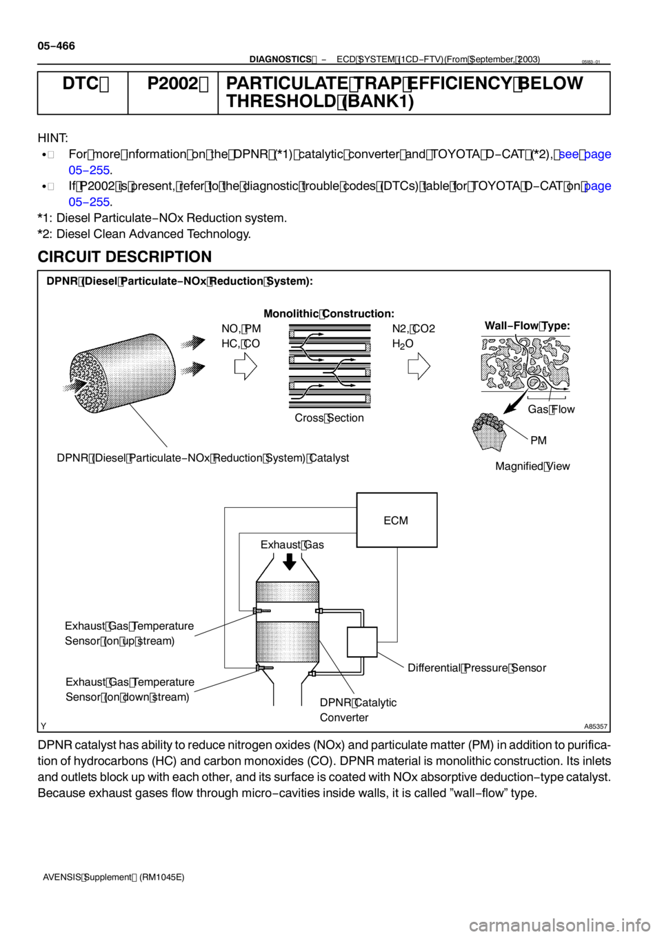
DPNR (Diesel Particulate−NOx Reduction System) Catalyst Monolithic Construction:
NO, PM
HC, CO N2, CO2
H
2O
Exhaust Gas Temperature
Sensor (on up stream) ECM
Exhaust Gas Temperature
Sensor (on down stream)
Wall −Flow Type:
Differential Pressure Sensor
Cross Section
Magnified ViewGas Flow
PM
Exhaust Gas
DPNR (Diesel Particulate −NOx Reduction System):
DPNR Catalytic
Converter
05
−466
−
DIAGNOSTICS ECD SYSTEM (1CD −FTV)(From September, 2003)
AVENSIS Supplement (RM 1045E)
DTC P2002 PARTICULATE TRAP EFFICIENCY BELOW
THRESHOLD (BANK 1)
HINT:
S For more information on the DPNR (* 1) catalytic converter and TOYOTA D −CAT (*2), see page
05 −255.
S If P2002 is present, refer to the diagnostic trouble codes (DTCs) table for TOYOTA D −CAT on page
05 −255.
* 1 : Diesel Particulate −NOx Reduction system.
*2: Diesel Clean Advanced Technology.
CIRCUIT DESCRIPTION
DPNR catalyst has ability to reduce nitrogen oxides (NOx) and particulate matter (PM) in addition to purifica-
tion of hydrocarbons (HC) and carbon monoxides (CO). DPNR material is monolithic construction. Its inlets
and outlets block up with each other, and its surface is coated with NOx absorptive deduction −type catalyst.
Because exhaust gases flow through micro −cavities inside walls, it is called ”wall −flow” type.
05I83 −01
Page 4398 of 5135

A85356
ECM
Exhaust Gas
Exhaust Gas Differential Pressure (kPa)
Differential Pressure Voltage (V)
1.530
0.750
0.530
0
−5.020.0100.0 Detect P1425 or P1428
5.000
4.700 4.800
0 0.400
Differential Pressure
Sensor
Property of Output Voltage:
Detect P1425 or P1427
DPNR Catalytic
Converter 05−458
− DIAGNOSTICSECD SYSTEM (1CD−FTV)(From September, 2003)
AVENSIS Supplement (RM1045E)
CIRCUIT DESCRIPTION
Two sensible portions of the differential pressure sensor are mounted before and after the DPNR (*2) catalyt-
ic converter and monitor exhaust gas differential pressure. The sensor itself is located far from the engine
assembly to reduce the influence of vibration, and is a semiconductor−type that is not influenced by exhaust
gases.
The ECM compares the exhaust gas pressure before and after DPNR catalytic converter by monitoring the
pressure using the up−and downstream sensible portions of the differential pressure sensor. If difference
between the pressure before and after the catalytic converter exceeds a standard level, the ECM judges
that the catalytic converter has clogged with particulate matter (PM). When once the ECM judges it, the ECM
begins to exercise the DPNR catalyst regeneration.
When output voltage of the sensor deviates from the normal operating range, the ECM interprets this as
malfunction of the sensor circuit, and sets DTC P1425, P1427, or P1428 and then illuminates the CHK ENG.
*2: Diesel Particulate−NOx Reduction system.
HINT:
If vacuum hoses of the differential pressure sensor for up−and downstream sensible portions are connected
to a upside down, the ECM interprets this as abnormal pressure difference, therefore DTC P1426 (Differen-
tial Pressure Sensor [Installation]) will be set and the CHK ENG will illuminate.
Page 4442 of 5135

− DIAGNOSTICSECD SYSTEM (1CD−FTV)(From September, 2003)
05−403
AVENSIS Supplement (RM1045E)
DTC P0488 EXHAUST GAS RECIRCULATION
THROTTLE POSITION CONTROL
RANGE/PERFORMANCE
CIRCUIT DESCRIPTION
The ECM opens and closes the intake shutter valve (throttle valve) using the rotary solenoid type actuator.
Upon opening and closing the valve, the exhaust gas recirculation volume is properly controlled. Also, en-
gine vibration and noise will be reduced by closing the valve when the engine is stopped.
DTC No.DTC Detection ConditionTrouble Area
P0488
Duty ratio during valve movement control stuck in its maximum
or minimum value for more than1second
(1trip detection logic)
SIntake shutter stuck
SIntake shutter does not move smoothly
SOpen or short in intake shutter circuit
SOpen or short in intake shutter position sensor circuit
SIntake shutter position sensor (built in intake shutter valve)
SECM
HINT:
After confirming DTC P0488, check the intake shutter position in the ”DIAGNOSIS / OBD/MOBD / DATA LIST
/ ALL / THROTTLE POS” using the hand−held tester.
Reference:
ConditionIntake Shutter (Throttle Valve) Position
Quickly accelerate the engine from idling to 3,000 rpmOpening angle varies smoothly
05I7P−01
Page 4586 of 5135
1111 7−01
A78441zNon−reusable part
N·m (kgf·cm, ft·lbf) : Specified torqueSeat Fixed Type:
Rear Seat Cushion Assy
Rear Floor Service Hole Cover
Fuel Pump Connector
Fuel Evaporation Tube
Sub−assy No. 2 Fuel Tank Main Tube
Sub−assy
Tube Joint ClipzFuel Pump Gauge Retainer
Fuel Suction
w/ Pump & Gauge Tube Assy
zFuel Suction Tube
Set Gasket x4
Fuel Tank Return Tube
11−28− FUELFUEL SUCTION W/ PUMP & GAUGE TUBE
ASSY (2AZ−FSE)
AVENSIS Supplement (RM1045E)
FUEL SUCTION W/ PUMP & GAUGE TUBE ASSY (2AZ−FSE)
COMPONENTS
Page 4596 of 5135

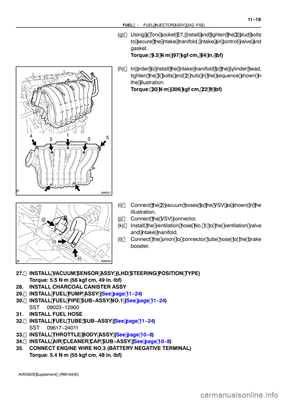
A88257
12345
A88256
(i)
(j)
(i)
−
FUEL FUEL INJECTOR ASSY (2AZ −FSE)
11 −19
AVENSIS Supplement (RM1045E)
(g) Using a Torx socket E7, install and tighten the 2 stud bolts
to secure the intake manifold, intake air control valve and
gasket.
Torque: 9.5 N �m (97 kgf �cm, 84 in. �lbf)
(h) In order to install the intake manifold to the cylinder head, tighten the 3 bolts and 2 nuts in the sequence shown in
the illustration.
Torque: 30 N �m (306 kgf �cm, 22 ft �lbf)
(i) Connect the 2 vacuum hoses to the VSV as shown in the illustration.
(j) Connect the VSV connector.
(k) Install the ventilation hose No. 1 to the ventilation valve and intake manifold.
(l) Connect the union to connector tube hose to the brake booster.
27. INSTALL VACUUM SENSOR ASSY (LHD STEERING POSITION TYPE) Torque: 5.5 N �m (56 kgf �cm, 49 in. �lbf)
28. INSTALL CHARCOAL CANISTER ASSY
29. INSTALL FUEL PUMP ASSY (See page 11 −24)
30. INSTALL FUEL PIPE SUB −ASSY NO.1 (See page 11 −24)
SST 09023 −12900
31. INSTALL FUEL HOSE
32. INSTALL FUEL TUBE SUB −ASSY (See page 11 −24)
SST 09617 −24011
33. INSTALL THROTTLE BODY ASSY (See page 10 −8)
34. INSTALL AIR CLEANER CAP SUB −ASSY (See page 10 −8)
35. CONNECT ENGINE WIRE NO.3 (BATTERY NEGATIVE TERMINAL) Torque: 5.4 N �m (55 kgf �cm, 48 in. �lbf)
Page 4600 of 5135

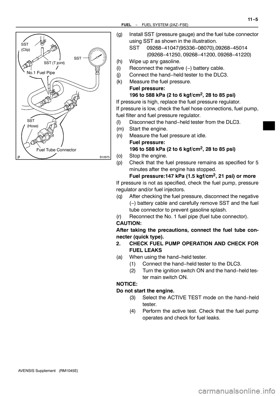
No.1 Fuel Pipe
Fuel Tube Connector
SST
(Clip)
SST (T joint)SST
SST
(Hose)
B12975
− FUELFUEL SYSTEM (2AZ−FSE)
11−5
AVENSIS Supplement (RM1045E)
(g) Install SST (pressure gauge) and the fuel tube connector
using SST as shown in the illustration.
SST 09268−41047(95336−08070),09268−45014
(09268−41250, 09268−41200, 09268−41220)
(h) Wipe up any gasoline.
(i) Reconnect the negative (−) battery cable.
(j) Connect the hand−held tester to the DLC3.
(k) Measure the fuel pressure.
Fuel pressure:
196 to 588 kPa (2 to 6 kgf/cm
2, 28 to 85 psi)
If pressure is high, replace the fuel pressure regulator.
If pressure is low, check the fuel hose connections, fuel pump,
fuel filter and fuel pressure regulator.
(l) Disconnect the hand−held tester from the DLC3.
(m) Start the engine.
(n) Measure the fuel pressure at idle.
Fuel pressure:
196 to 588 kPa (2 to 6 kgf/cm
2, 28 to 85 psi)
(o) Stop the engine.
(p) Check that the fuel pressure remains as specified for 5
minutes after the engine has stopped.
Fuel pressure:147 kPa (1.5 kgf/cm
2, 21 psi) or more
If pressure is not as specified, check the fuel pump, pressure
regulator and/or fuel injectors.
(q) After checking the fuel pressure, disconnect the negative
(−) battery cable and carefully remove SST and the fuel
tube connector to prevent gasoline splash.
(r) Reconnect the No. 1 fuel pipe (fuel tube connector).
CAUTION:
After taking the precautions, connect the fuel tube con-
necter (quick type).
2. CHECK FUEL PUMP OPERATION AND CHECK FOR
FUEL LEAKS
(a) When using the hand−held tester.
(1) Connect the hand−held tester to the DLC3.
(2) Turn the ignition switch ON and the hand−held tes-
ter main switch ON.
NOTICE:
Do not start the engine.
(3) Select the ACTIVE TEST mode on the hand−held
tester.
(4) Perform the active test. Check that the fuel pump
operates and check for fuel leaks.
Page 4619 of 5135

A80117
A
B
C
D
E
A90797
Front
A61189
10 11
12 1314
1516 1718 2 1
4 56 3
78 9(A) (A) (A)
(B) (B) (B) (B)
(B) (B) (B)(B) (B) (B)(A)
− ENGINE MECHANICALCYLINDER HEAD GASKET (1CD−FTV)(From
September, 2003)14−171
AVENSIS Supplement (RM1045E)
(2) Select a new gasket among A to E using the matrix
below.
New gasket matrix:
Piston Protrusion mm (in.)Gasket Size
0.165 to 0.220 (0.0065 to 0.0087)A
0.220 to 0.270 (0.0087 to 0.0106)B
0.270 to 0.320 (0.0106 to 0.0126)C
0.320 to 0.370 (0.0126 to 0.0146)D
0.370 to 0.425 (0.0146 to 0.0167)E
(c) Place the selected new cylinder head gasket on the cylin-
der block.
NOTICE:
Pay attention to the mounting orientation.
81. INSTALL CYLINDER HEAD SUB−ASSY
HINT:
SThe cylinder head bolts are tightened in 4 successive
steps (steps (c), (e), (f) and (g)).
SIf the cylinder head bolt is broken or deformed, replace it
with a new bolt.
(a) Apply a light coat of engine oil to the threads of the cylin-
der head bolts and plate washers.
(b) Install the plate washer to the cylinder head bolt.
(c) Using several steps, install and tighten the 18 cylinder
head bolts uniformly in the sequence shown in the illustra-
tion.
Torque: 45 N�m (459 kgf�cm, 33 ft�lbf)
HINT:
See the table below for the bolt length.
Bolt TypeBolt Length
(A)160mm (6.30 in.)
(B)104mm (4.09 in.)
If the cylinder head bolt does not meet the specified torque, re-
place the cylinder head bolt with a new bolt.