Page 2756 of 5135

D30068
Blue Mark
42±14
±
CLUTCH CLUTCH MASTER CYLINDER ASSY (MTM)
AVENSIS REPAIR MANUAL (RM1018E)
7. REMOVE C")
D30782
RHD Steering Position Type:
LHD Steering Position Type:
MP Grease
D30069
SST(s)
D30068
Blue Mark
42±14
±
CLUTCH CLUTCH MASTER CYLINDER ASSY (MTM)
AVENSIS REPAIR MANUAL (RM1018E)
7. REMOVE CLUTCH MASTER CYLINDER ASSY
(a) Remove the 2 nuts clutch master cylinder assy and gasket.
8. INSTALL CLUTCH MASTER CYLINDER ASSY
(a) Install the clutch master cylinder assy and gasket with the 2 nuts. Torque: 12 N �m (120 kgf �cm, 9 ft �lbf)
9. INSTALL CLUTCH MASTER CYLINDER PUSH ROD CLEVIS W/HOLE PIN
(a) Apply MP grease to the contact surface of the hole pin and clevis bush.
(b) Connect the clevis to the clutch pedal assy with the hole pin.
HINT:
�RHD steering position type:
Install the hole pin from the right side of the vehicle.
�LHD steering position type:
Install the hole pin from the left side of the vehicle.
(c) Install the clip to the hole pin.
10. CONNECT CLUTCH MASTER CYLINDER TO FLEXIBLE HOSE TUBE
(a) Using SST(s), connect the flexible hose tube. SST 09023±00100
Torque: 15 N �m (155 kgf �cm, 11 ft �lbf)
11. CONNECT CLUTCH RESERVOIR TUBE
(a) Connect the clutch reservoir tube with the clip to the clutch master cylinder assy.
NOTICE:
Connect the clutch reservoir tube so as not be twisted.
12.INSTALL BRAKE BOOSTER ASSY (LHD STEERING POSITION TYPE) (See page 32±19)
13. INSTALL BRAKE MASTER CYLINDER SUB±ASSY (LHD STEERING POSITION TYPE) (See page 32±13)
14.BLEED BRAKE LINE (LHD STEERING POSITION TYPE) (See page 32±4)
Page 2758 of 5135
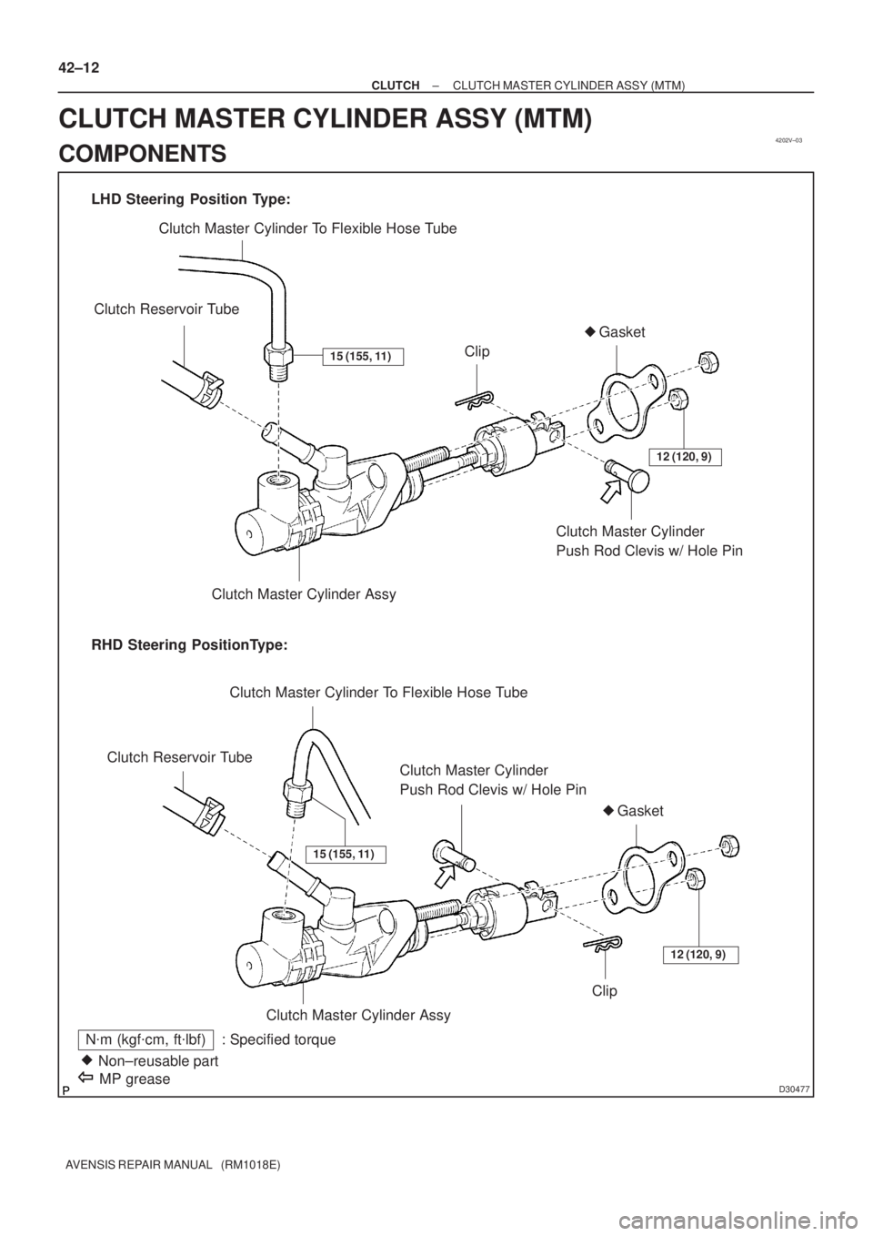
4202V±03
D30477
LHD Steering Position Type:
RHD Steering PositionType:Clutch Master Cylinder To Flexible Hose Tube
Clutch Reservoir Tube
Clutch Master Cylinder
Push Rod Clevis w/ Hole Pin�Gasket
Clip
Clutch Master Cylinder Assy
Clutch Master Cylinder To Flexible Hose Tube
Clutch Reservoir Tube
Clutch Master Cylinder
Push Rod Clevis w/ Hole Pin
Clutch Master Cylinder AssyClip�Gasket
N�m (kgf�cm, ft�lbf) : Specified torque
Non±reusable part �
12 (120, 9)
12 (120, 9)
15 (155, 11)
15 (155, 11)
MP grease
42±12
± CLUTCHCLUTCH MASTER CYLINDER ASSY (MTM)
AVENSIS REPAIR MANUAL (RM1018E)
CLUTCH MASTER CYLINDER ASSY (MTM)
COMPONENTS
Page 2915 of 5135
550ZJ±01
I36136
I32396
E
IN
IG
± HEATER & AIR CONDITIONERHOT GAS TYPE POWER HEATER SYSTEM
55±23
AVENSIS REPAIR MANUAL (RM1018E)
INSPECTION
1. INSPECT W/RECEIVER CONDENSER ASSY
(a) Apply voltage between terminals and check that the re-
frigerant passages switch.
2. INSPECT HETER SWITCH ASSY
(a) Check that the continuity to the follwing terminals.
Standard:
Heater switch conditionConnecting terminalsStandard value
ONIG ± INContinuity
OFFIG ± INNo continuity
ONIG ± EContinuity
OFFIG ± ENo continuity
Page 2916 of 5135

550ZI±01
I35437
Connector ºBº Wire harness side:
Connector ºAº
I36091
Connector ºBº From back side:
Connector ºAº 55±22
± HEATER & AIR CONDITIONERHOT GAS TYPE POWER HEATER SYSTEM
AVENSIS REPAIR MANUAL (RM1018E)
HOT GAS TYPE POWER HEATER SYSTEM
ON±VEHICLE INSPECTION
1. INSPECT AIR CONDITIONING CONTROL ASSY
(a) Disconnect the connector from air conditioning control assy and inspect the connector on wire harness
side, as shown in the table.
Symbols (Terminal No.)Wiring ColorConditionSTD Voltage (V)
SOL+ (B17) ±
GND (B40)R ± W±BStart engine
Compressor: OperatePulse generation
MGV (B14) ±
GND (B40) (*1)R±Y ± W±BStart engine
Compressor: OperatePulse generation
HOT GAS IN (B22) ±
GND (B40) (*1)R±Y ± W±BIG SW: ON
Hot Gas SW: ONBattery positive voltage
If circuit is not as specified, try replacing the air conditioning control assy with a new one. If the circuit is not
as specified, inspect the circuits connected to the other parts.
(b) Connect the connector to air conditioning control assy and inspect wire harness side connector from
the back side, as shown in the table.
Symbols (Terminal No.)ConditionSpecified condition
HI (A4) ± GND (A1)Ignition switch ON
Turn blower dial: OFF � HINo continuity �Continuity
M2 (A5) ± GND (A1)Ignition switch ON
Turn blower dial: OFF � M2No continuity �Continuity
M1 (A6) ± GND (A1)Ignition switch ON
Turn blower dial: OFF � M1No continuity �Continuity
GND (A1) ± Body groundIgnition switch ON
Turn blower dial: OFF � LONo continuity �Continuity
Page 2922 of 5135

5. DIAGNOSTIC TROUBLE CODE CHART
If a malfunction code is displayed during the DTC check, check")
± HEATER & AIR CONDITIONERCOMBUSTION TYPE POWER HEATER SYSTEM
55±17
AVENSIS REPAIR MANUAL (RM1018E)
5. DIAGNOSTIC TROUBLE CODE CHART
If a malfunction code is displayed during the DTC check, check the circuit listed for the code in the table below
and proceed to the appropriate page.
DTC No.Description of faultComment / Remedy
000No malfunction±
010
011Overvoltage shutoff
Undervoltage shutoffVoltage between 1 and 5 at connector A > 16 V
Voltage between 1 and 5 at connector A < 10.2 V
(Voltage values must be present > 20 seconds)
Check battery, regulator and electrical leads.
012Overheating
Check temperature at temperature or overheating sensor >
125 �C
Check water circuit.
014Possible overheating detected
(Hardware threshold value)
Difference of measured values at temperature sensor > 15 �C
(min. 70 �C water temperature and metering pump in opera-
tion);
Check temperature sensor and overheating sensor, replace if
necessary.
017Overheating detected
(Hardware threshold value)
Temperature at temperature or overheating sensor > 130 �C,
emergency OFF if DTC No. 012 or 014s not applicable;
Check water circuit, temperature sensor and overheating sen-
sor, replace if necessary.
020Glow plug breakCheck glow plug, replace if necessary.
021Glow plug output overloadCheck glow plug, replace if necessary.
030Combustion air blower motor
EMF outside perm. range.Blower impeller or burner motor fammed (frozen solid, dirty,
etc.)
Remedy jam, replace burner motor if necessary.
031Combustion air blower motor breakCheck the lead to combustion air motor (burner motor) for
continuity, replace if necessary.
032Combustion air blower motor short±circuit
Check combustion air blower motor (burner motor), replace if
necessary.
Check supply lead (chafed, etc.).
047Metering pump short±circuitCheck the supply lead to metering pump for short±circuit,
check metering pump, replace if necessary.
048Metering pump breakCheck the supply lead to metering pump for continuity, remedy
break, replace metering pump if necessary.
051Cold blow time exceeded
At start, if flame sensor above 70 �C, > 240 sec.;
Check exhaust gas combustion air supply, check flame sen-
sor, replace if necessary.
052Safety time exceeded
When all perm. start attempts used up;
Check the fuel delivery and fuel supply.
Check exhaust gas and combustion air ducts.
054Flame cutout, High settingCheck the fuel delivery and fuel supply.
Check exhaust gas combustion air ducts.
056Flame cutout, LOW setting
Check exhaust gas combustion air ducts.
If combustion OK � Check the flame sensor, replace if neces-
sary.
060Temperature control sensor break
Check connecting leads.
Resistance value between 2 and 10 connector B > 2 M� (if
break)
061Temperature control sensor short±circuit
Check connecting leads.
Resistance value between 2 and 10 at connector B < 2 M� (If
short± circuit)
064Flame sensor break
Check connecting leads.
Resistance value between 7 and 14 at connector B > 3,040 �
(If break)
065Flame sensor short±circuit
Check connecting leads.
Resistance value between 7 and 14 at connector B > 780 � (If
short±circuit)
Page 3000 of 5135

5. REMOVE DISCHARGE TUBE SUB±ASSY (W/ HOT GAS HEATER)
(a) Remove the 2 bolts")
I35337
I35336
I35339
I35340
55±94
±
HEATER & AIR CONDITIONER W/RECEIVER CONDENSER ASSY
AVENSIS REPAIR MANUAL (RM1018E)
5. REMOVE DISCHARGE TUBE SUB±ASSY (W/ HOT GAS HEATER)
(a) Remove the 2 bolts and disconnect the discharge tube
sub±assy from the w/ receiver condenser assy.
(b) Remove 2 O±rings from the discharge tube sub±assy.
NOTICE:
Seal the opening of the disconnected parts using vinyl tape
to prevent moisture and foreign matters from entering.
6. REMOVE LIQUID TUBE SUB±ASSY B (RHD(1CD±FTV) STEERING POSITION TYPE)
(a) Remove the bolt and disconnect the liquid tube sub±assy B from w/ receiver condenser assy.
(b) Remove the O±ring from the liquid tube sub±assy B.
NOTICE:
Seal the opening of the disconnected parts using vinyl tape
to prevent moisture and foreign matters from entering.
7. REMOVE HOOD LOCK ASSY
(a) Remove the 3 bolts and the hood lock assy.
8.REMOVE HIGH PITCHED HORN ASSY (See page 69±5)
9.REMOVE LOW PITCHED HORN ASSY (See page 69±4) 10. REMOVE HOOD LOCK SUPPORT BRACE
(a) Remove the 5 bolts and the hood lock support brace.
Page 3003 of 5135

20. I N S TA L L M A G N E T VA LV E A S S Y ( W / H O T G A S
HEATER)
(a) Ins")
I35344
I35343
I35342
I35336
± HEATER & AIR CONDITIONERW/RECEIVER CONDENSER ASSY
55±97
AVENSIS REPAIR MANUAL (RM1018E)
20. I N S TA L L M A G N E T VA LV E A S S Y ( W / H O T G A S
HEATER)
(a) Install the magnet valve assy with the 4 bolts.
Torque: 3.4 N�m (35 kgf�cm, 30 in.�lbf)
21. INSTALL REFRIGERANT FILTER (W/ HOT GAS
HEATER)
(a) Install the refrigerant filter to the discharge tube.
22. INSTALL DISCHARGE TUBE (W/ HOT GAS HEATER)
(a) Install the discharge tube with the 2 bolts.
Torque: 5.4 N�m (55 kgf�cm, 47 in.�lbf)
23. INSTALL LIQUID TUBE SUB±ASSY B (RHD(1CD±FTV)
STEERING POSITION TYPE)
(a) Remove the attached vinyl tape from the tube and the
connecting part of the w/ receiver condenser assy.
(b) Sufficiently apply compressor oil to a new O±ring and the
fitting surface of the pipe joint.
Compressor oil: ND±OIL 8 or equivalent
(c) Install the O±ring on the liquid tube sub±assy B.
(d) Install the liquid tube sub±assy B on the w/ receiver con-
denser assy with the bolt.
Torque: 5.4 N�m (55 kgf�cm, 47 in.�lbf)
24. INSTALL DISCHARGE TUBE SUB±ASSY (W/ HOT
GAS HEATER)
(a) Remove the attached vinyl tape from the tube and the
connecting part of the w/ receiver condenser assy.
(b) Sufficiently apply compressor oil to a new 2 O±rings and
the fitting surface of the pipe joint.
Compressor oil: ND±OIL 8 or equivalent
(c) Install the O±ring on the discharge tube sub±assy.
Page 3638 of 5135
D09176
D09177
AT0103
D09637
40±16
± AUTOMATIC TRANSMISSION / TRANSAUTOMATIC TRANSAXLE ASSY (U241E)
U241E A/T REPAIR MANUAL (RM840U)
9. FIX AUTOMATIC TRANSAXLE ASSY
10. REMOVE AUTOMATIC TRANSAXLE OIL PAN
SUB±ASSY
(a) Remove the 18 bolts.
(b) Remove the oil pan and 2 magnets.
11. REMOVE AUTOMATIC TRANSAXLE OIL PAN GASKET
(a) Remove the gasket from the oil pan.
12. INSPECT AUTOMATIC TRANSAXLE OIL PAN
SUB±ASSY
(a) Remove the magnets and use them to collect any steel
chips. Examine the chips and particles in the pan and on
the magnet to determine what type of wear has occurred
in the transaxle:
Steel (magnetic).... bearing, gear and plate wear
Brass (non±magnetic).... bushing wear
13. REMOVE TRANSMISSION WIRE
(a) Remove the 5 connectors from the shift solenoid valves.
(b) Remove the bolt, clamp and ATF temperature sensor.

INSPECTION
1. INSPECT W/RECEIVER CONDENSER ASSY
(a) Apply voltage b")

U241E A/T REPAIR MANUAL (RM840U)
9. FIX AUTOMATIC TRANSAXLE ASSY
10. REMOVE AUTOMATIC TRANSAXLE O")