Page 1965 of 5135

AVENSIS REPAIR MANUAL (RM1018E)
22. REMOVE FUEL TANK RETURN TUBE (1AZ±FSE
ENGINE TYP")
A77894
A77891
A77892
A77893
Upper
Fuel Tank
Rear
Hose Clamp
A81617
Push 11±98
± FUELFUEL TANK ASSY (GASOLINE)
AVENSIS REPAIR MANUAL (RM1018E)
22. REMOVE FUEL TANK RETURN TUBE (1AZ±FSE
ENGINE TYPE)
(a) Unfasten the 5 claws and remove the fuel tank return tube
from the fuel tank.
23. REMOVE FUEL EVAPORATION TUBE SUB±ASSY
NO.2
(a) Unfasten the 4 claws and remove the fuel evaporation
tube from the fuel tank.
24. REMOVE FUEL TANK MAIN TUBE SUB±ASSY
(a) Unfasten the 4 claws and remove the fuel tank main tube
from the fuel tank.
25. INSTALL FUEL TANK MAIN TUBE SUB±ASSY
26. INSTALL FUEL EVAPORATION TUBE SUB±ASSY
NO.2
(a) Install the hose clamp as shown in the illustration.
27. INSTALL FUEL TANK RETURN TUBE (1AZ±FSE
ENGINE TYPE)
28. INSTALL FUEL TANK ASSY
Torque: 40 N�m (400 kgf�cm, 29 ft�lbf)
29. CONNECT FUEL EVAPORATION TUBE SUB±ASSY
NO.2
(a) Push in the fuel tube connector to the pipe until it makes
ºclickº sound.
NOTICE:
�Check if there is any damage or foreign objects on the
connected part.
�After connecting, check if the fuel tube connector and
the pipe are securely connected by pulling on them.
Page 1966 of 5135

11±99
AVENSIS REPAIR MANUAL (RM1018E)
30. CONNECT FUEL TANK MAIN TUBE SUB±ASSY
(a) Push in the fuel tube c")
A81618
Push
2
1
Retainer
A77857
A78440
New Gasket
A77857
± FUELFUEL TANK ASSY (GASOLINE)
11±99
AVENSIS REPAIR MANUAL (RM1018E)
30. CONNECT FUEL TANK MAIN TUBE SUB±ASSY
(a) Push in the fuel tube connector to the pipe until it makes
ºclickº sound, and then push up the retainer to the claws
lock.
NOTICE:
�Check if there is any damage or foreign objects on the
connected part.
�After connecting, check if the fuel tube connector and
the pipe are securely connected by pulling on them.
31. CONNECT FUEL TANK RETURN TUBE (1AZ±FSE
ENGINE TYPE)
32. CONNECT FUEL TANK TO FILLER PIPE HOSE
33. CONNECT BREATHER TUBE FUEL HOSE
34. INSTALL PARKING BRAKE CABLE ASSY NO.3
Torque: 5.0 N�m (51 kgf�cm, 44 in.�lbf)
35. INSTALL PARKING BRAKE CABLE ASSY NO.2
Torque: 5.0 N�m (51 kgf�cm, 44 in.�lbf)
36. INSTALL FUEL TANK PROTECTOR NO.1
Torque: 5.4 N�m (55 kgf�cm, 48 in.�lbf)
37. INSTALL EXHAUST PIPE ASSY CENTER
(1ZZ±FE/3ZZ±FE ENGINE TYPE)
(a) Compression spring inspection
(1) Using vernier calipers, measure the free length of
the compression spring.
Minimum length:
41.5 mm (1.634 in.) for front x manifold
38.5 mm (1.516 in.) for front x tail
If the free length is less than minimum, replace the compression
spring.
(b) Install each new gasket to the exhaust manifold and the
exhaust pipe front as shown in the illustration.
(c) Install the exhaust pipe front to the 2 exhaust pipe sup-
ports
(d) Tighten the 4 compression springs and 4 bolts.
Torque: 43 N�m (440 kgf�cm, 32 ft�lbf)
(e) Install the grommet. (w/o HID Sensor)
(f) Connect the heated oxygen sensor connector.
(g) Install the floor carpet with the 2 clips. (w/o HID Sensor)
38. INSTALL EXHAUST PIPE ASSY CENTER
(1AZ±FE/1AZ±FSE ENGINE TYPE)
(a) Compression spring inspection
(1) Using vernier calipers, measure the free length of
the compression spring.
Minimum length: 38.5 mm (1.516 in.)
If the free length is less than minimum, replace the compression
spring.
Page 1967 of 5135

AVENSIS REPAIR MANUAL (RM1018E)
(b)Install a new gasket to the the exhaust pipe center (ex- haust pipe tail side) as shown in the illustrat")
A78440
New Gasket
11±100
±
FUEL FUEL TANK ASSY(GASOLINE)
AVENSIS REPAIR MANUAL (RM1018E)
(b)Install a new gasket to the the exhaust pipe center (ex- haust pipe tail side) as shown in the illustration.
(c)Install a new gasket (exhaust pipe front side) and the ex-
haust pipe center to the 2 exhaust pipe supports.
(d)Tighten the 2 compression springs and 4 bolts. Torque: 43 N �m (440 kgf �cm, 32 ft �lbf)
39.ADD FUEL
40.INSTALL FUEL SUCTION W/PUMP & GAGE TUBE ASSY (See page 11±85) SST 09808±14010
41.CONNECT FUEL EVAPORATION TUBE SUB±ASSY NO.2 (See page 11±85)
42.CONNECT FUEL TANK MAIN TUBE SUB±ASSY (See page 11±85)
43.CONNECT FUEL TANK RETURN TUBE (1AZ±FSE ENGINE TYPE) (See page 11±85)
44. CHECK FOR FUEL LEAKS
HINT:
�1ZZ±FE/3ZZ±FE: 11±5
�1AZ±FE: 11±19
�1AZ±FSE: 11±33
45. CHECK FOR EXHAUST GAS LEAKS
46.INSTALL FLOOR PANEL BRACE FRONT (See page 15±2)
47. INSTALL REAR FLOOR SERVICE HOLE COVER
48.INSTALL REAR SEAT CUSHION ASSY (SEAT FIXED TYPE) (See page 72±32)
49. INSTALL FRONT FLOOR FOOTREST (W/O HID SENSOR)
Page 1968 of 5135
110U6±01
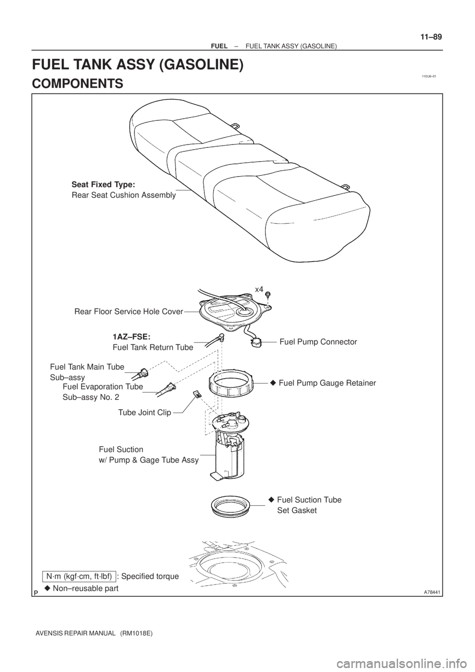
A78441� Non±reusable part
N´m (kgf´cm, ft´lbf) : Specified torqueSeat Fixed Type:
Rear Seat Cushion Assembly
Rear Floor Service Hole Cover
Fuel Pump Connector
Fuel Evaporation Tube
Sub±assy No. 2 Fuel Tank Main Tube
Sub±assy
Tube Joint Clip� Fuel Pump Gauge Retainer
Fuel Suction
w/ Pump & Gage Tube Assy
� Fuel Suction Tube
Set Gasket x4
1AZ±FSE:
Fuel Tank Return Tube
± FUELFUEL TANK ASSY (GASOLINE)
11±89
AVENSIS REPAIR MANUAL (RM1018E)
FUEL TANK ASSY (GASOLINE)
COMPONENTS
Page 2060 of 5135

AVENSIS REPAIR MANUAL (RM1018E)
137. INSTALL BATTERY CARRIER
(a) Install the battery carrier and bracket with the 4 bo")
A76714
A78459
14±44
±
ENGINE MECHANICAL PARTIAL ENGINE ASSY (1ZZ±FE/3ZZ±FE)
AVENSIS REPAIR MANUAL (RM1018E)
137. INSTALL BATTERY CARRIER
(a) Install the battery carrier and bracket with the 4 bolts. Torque: 12.8 N �m (131 kgf �cm, 9 ft �lbf)
138. INSTALL BATTERY Torque: 5.0 N �m (51 kgf �cm, 44 in. �lbf)
139. INSTALL RADIATOR SUPPORT NO.1
(a) Install the 2 radiator supports with the 2 bolts. Torque: 19 N �m (194 kgf �cm, 14 ft �lbf)
140.INSTALL ACCELERATOR CONTROL CABLE ASSY (1ZZ±FE ENGINE TYPE) (See page 10±9)
141.INSTALL ACCELERATOR CONTROL CABLE ASSY (3ZZ±FE ENGINE TYPE) (See page 10±15)
142. INSTALL AIR CLEANER CASE SUB±ASSY
(a) Install the air cleaner case with the 3 bolts. Torque: 5.0 N �m (51 kgf �cm, 44 in. �lbf)
143.INSTALL AIR CLEANER ASSEMBLY WITH HOSE (See page 10±9 or 10±15)
144. INSTALL CYLINDER HEAD COVER NO.2
(a) Install the cylinder head cover with the 2 nuts and 2 clips.Torque: 7.0 N �m (71 kgf �cm, 62 in. �lbf)
145. INSTALL FRONT WHEELS Torque: 103 N �m (1,050 kgf �cm, 76 ft �lbf)
146. ADD AUTOMATIC TRANSAXLE FLUID (A/T TRANSAXLE)
147. ADD ENGINE OIL
148.ADD ENGINE COOLANT (See page 16±7)
149. CHECK FOR ENGINE OIL LEAKS
150.CHECK FOR ENGINE COOLANT LEAKS(See page 16±7)
151. CHECK FOR FUEL LEAKS
152. CHECK FOR EXHAUST GAS LEAKS
153.CHECK IDLE SPEED AND IGNITION TIMING(See page 14±1)
SST 09843±18040
154.INSPECT CO/HC(See page 14±1)
155.INSPECT AND ADJUST FRONT WHEEL ALIGNMENT (See page 26±6)
156. CHECK ABS SPEED SENSOR SIGNAL
Page 2069 of 5135

14±121
AVENSIS REPAIR MANUAL (RM1018E)
REPLACEMENT
1.DISCHARGE FUEL SYSTEM PRESSURE (See page 11±19)
2.REMOVE FRONT WHEELS")
141BF±01
A77281
A77301
±
ENGINE MECHANICAL PARTIAL ENGINE ASSY(1AZ±FE)
14±121
AVENSIS REPAIR MANUAL (RM1018E)
REPLACEMENT
1.DISCHARGE FUEL SYSTEM PRESSURE (See page 11±19)
2.REMOVE FRONT WHEELS
3.REMOVE RADIATOR SUPPORT OPENING COVER
4.REMOVE ENGINE ROOM COVER SIDE
5.REMOVE ENGINE UNDER COVER RH
6.REMOVE ENGINE UNDER COVER LH
7.DRAIN COOLANT (See page 16±19)
8.DRAIN ENGINE OIL
(a)Install a new gasket and the drain plug after draining engine oil.
Torque: 25 N �m (255 kgf �cm,18 ft �lbf)
9.DRAIN MANUAL TRANSAXLE OIL (M/T TRANSAXLE) Torque: 49 N �m (500 kgf �cm,36 ft �lbf)
10.DRAIN AUTOMATIC TRANSAXLE FLUID (A/T TRANSAXLE) (See page 40±2)
11.REMOVE ENGINE COVER SUB±ASSY NO.1
(a)Remove 2 nuts and the cylinder head cover No. 1.
12.DISCONNECT RADIATOR HOSE INLET
13.DISCONNECT RADIATOR HOSE OUTLET 14.SEPARATE RADIATOR RELAY BLOCK
(a)Remove 2 bolts and separate the radiator relay block.
15.SEPARATE COOLER REFRIGERANT SUCTION HOSE NO.1 (RHD(W/ AIR CONDITIONER) STEERING POSITION TYPE)
(a)Remove a bolt and separate the suction hose No. 1.
16.REMOVE RADIATOR ASSY (See page 16±24)
17.REMOVE FAN AND GENERATOR V BELT (See page 14±105)
18.REMOVE GENERATOR ASSY (See page 19±20)
19. REMOVE COMPRESSOR AND MAGNETIC CLUTCH (W/ AIR CONDITIONING)
(a) Remove 4 bolts and separate the compressor and magnetic clutch.
HINT:
Secure the hoses off to the side instead of detaching.
Page 2085 of 5135
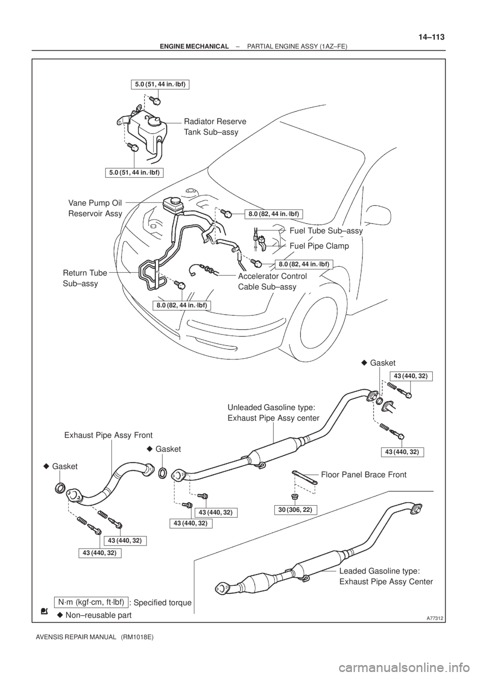
A77312
30 (306, 22)
Radiator Reserve
Tank Sub±assy
Fuel Tube Sub±assy
Unleaded Gasoline type:
Exhaust Pipe Assy center
� Gasket
� Gasket� Gasket
Floor Panel Brace Front
Leaded Gasoline type:
Exhaust Pipe Assy Center Vane Pump Oil
Reservoir Assy
Accelerator Control
Cable Sub±assy
Fuel Pipe Clamp
Exhaust Pipe Assy Front
8.0 (82, 44 in.�lbf)
8.0 (82, 44 in.�lbf)
8.0 (82, 44 in.�lbf)
Return Tube
Sub±assy
43 (440, 32)
5.0 (51, 44 in.�lbf)
N´m (kgf´cm, ft´lbf)
: Specified torque
� Non±reusable part
43 (440, 32)
43 (440, 32)
43 (440, 32)
43 (440, 32)
43 (440, 32)
5.0 (51, 44 in.�lbf)
± ENGINE MECHANICALPARTIAL ENGINE ASSY (1AZ±FE)
14±113
AVENSIS REPAIR MANUAL (RM1018E)
Page 2091 of 5135
A77317
Intake ManifoldIgnition Coil
Ventilation Hose No. 2
Ventilation Hose
Unleaded type:
Manifold Converter
Insulator No. 1 Intake Manifold Insulator
No. 1
V±ribbed Belt
Tensioner ASSY
Unleaded type:
Exhaust Manifold
Converter Sub±assy
Exhaust Manifold Stay
Exhaust Manifold
Stay No. 2 Manifold Converter
Insulator No. 1
Exhaust Manifold
Converter Sub±assy
N´m (kgf´cm, ft´lbf)
: Specified torque
� Non±reusable part
9.0 (92, 80 in.�lbf)
� Gasket� Gasket
12 (122, 9.0)
12 (122, 9.0)
37 (378, 27)
44 (449, 32)
44 (449, 32)
44 (449, 32)
� Gasket
Leaded type:
30 (306, 22)
30 (306, 22)
30 (306, 22)
12 (122, 9.0)
± ENGINE MECHANICALPARTIAL ENGINE ASSY (1AZ±FE)
14±119
AVENSIS REPAIR MANUAL (RM1018E)