Page 1589 of 5135
B66771
KSW
W±B8 U1
Unlock Warning Switch Assy
W±B
IP5
+B GROUND 1
W±R W±B
2
1Instrument Panel J/B Assy
PRG
RDA 16
2PRG
RDA D6
Door Control Receiver
7Integration
Relay
IC2 I14 3 G±Y
L±W 16
7
To
Battery
DA Y
IO*
1
6 8
Center
J/BIC2 G±Y
L±W
CA CD
AJ16
J/C LHD Models
19 I14
A W±B
IL*
2*1: Gasoline Engine
*2: 1CD±FTV
± DIAGNOSTICSWIRELESS DOOR LOCK CONTROL SYSTEM
05±1575
AVENSIS REPAIR MANUAL (RM1018E)
ONLY WIRELESS CONTROL FUNCTION DOES NOT OPERATE
(PREPARE NEW OR NORMAL TRANSMITTER OF THE SAME
TYPE VEHICLE)
CIRCUIT DESCRIPTION
The door control receiver receives a signal from the transmitter and sends this signal to the integration relay.
Then, the integration relay controls door operation by sending a door LOCK/UNLOCK signal and a luggage
door (back door) unlock signal to each door lock motor.
WIRING DIAGRAM
05BNB±01
Page 1832 of 5135

(b)
A77919
10±34
±
ENGINE CONTROL SYSTEM KNOCK SENSOR(1AZ±FE)
AVENSIS REPAIR MANUAL (RM1018E)
REPLACEMENT
1.DISCHARGE FUEL SYSTEM PRESSURE (See page 11±15)
2.REMOVE E")
100FL±01
A77917
A77918
(a)
(b)
A77919
10±34
±
ENGINE CONTROL SYSTEM KNOCK SENSOR(1AZ±FE)
AVENSIS REPAIR MANUAL (RM1018E)
REPLACEMENT
1.DISCHARGE FUEL SYSTEM PRESSURE (See page 11±15)
2.REMOVE ENGINE ROOM COVER SIDE (See page 10±26)
3.REMOVE RADIATOR SUPPORT OPENING COVER (See page 10±26)
4.ENGINE COOLANT (See page 16±19)
5.REMOVE ENGINE COVER SUB±ASSY NO.1 (See page 10±26)
6.REMOVE AIR CLEANER CAP SUB±ASSY (See page 10±26)
7.SEPARATE ACCELERATOR CONTROL CABLE ASSY (See page 10±26)
8.REMOVE THROTTLE BODY ASSY (See page 10±26)
9.DISCONNECT FUEL TUBE SUB±ASSY (See page 11±26) SST 09268±21010
10.REMOVE FUEL DELIVERY PIPE SUB±ASSY (See page 11±26)
11. REMOVE VARIABLE RESISTOR (LHD STEERINGPOSITION TYPE, LEADED GASOLINE)
(a) Disconnect the variable resistor connector.
(b) Remove the bolt, and then remove the variable resistor.
12. REMOVE CHARCOAL CANISTER ASSY
(a) Disconnect the charcoal canister outlet hose No. 1.
(b) Disconnect the fuel hose.
(c) Pull up and remove the charcoal canister.
13. DISCONNECT HEATER INLET WATER HOSE
Page 1834 of 5135

AVENSIS REPAIR MANUAL (RM1018E)
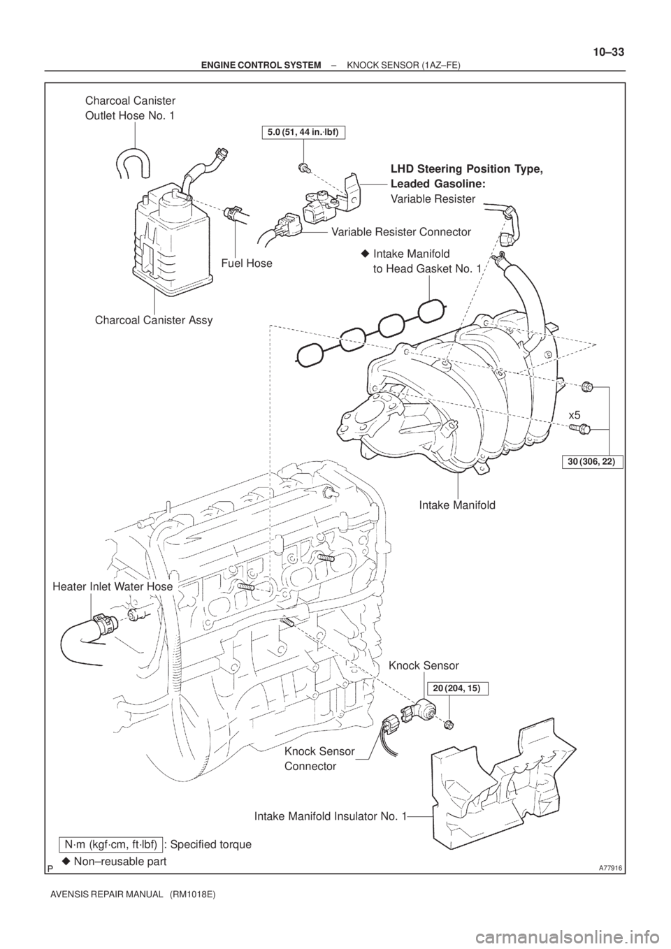
18.INSTALL INTAKE MANIFOLD INSULATOR NO.1
19.INSTALL INTAKE MANIFOLD
(a)Install a new gasket to the intake manif")
10±36
±
ENGINE CONTROL SYSTEM KNOCK SENSOR(1AZ±FE)
AVENSIS REPAIR MANUAL (RM1018E)
18.INSTALL INTAKE MANIFOLD INSULATOR NO.1
19.INSTALL INTAKE MANIFOLD
(a)Install a new gasket to the intake manifold.
(b)Install the intake manifold with the 5 bolts and 2 nuts. Torque: 30 N �m (306 kgf �cm, 22 ft �lbf)
(c)Install the wire harness clamp.
(d)Connect the union to connector tube hose.
20.CONNECT HEATER INLET WATER HOSE
21.INSTALL CHARCOAL CANISTER ASSY
22.INSTALL VARIABLE RESISTOR (LHD STEERING POSITION TYPE, LEADED GASOLINE) Torque: 5.0 N �m (51 kgf �cm, 44 in. �lbf)
23.INSTALL FUEL DELIVERY PIPE SUB±ASSY (See page 11±26)
24.CONNECT FUEL TUBE SUB±ASSY (See page 11±26)
25.INSTALL THROTTLE BODY ASSY (See page 10±26)
26.INSTALL ACCELERATOR CONTROL CABLE ASSY (See page 10±26)
27. INSTALL AIR CLEANER CAP SUB±ASSY
28.ADD ENGINE COOLANT (See page 16±19)
29.CHECK FOR ENGINE COOLANT LEAKS (See page 16±13)
30.CHECK FOR FUEL LEAKS (See page 11±19)
31.INSTALL ENGINE COVER SUB±ASSY NO.1 (See page 10±26)
32. INSTALL ENGINE ROOM COVER SIDE
33. INSTALL RADIATOR SUPPORT OPENING COVER
Page 1838 of 5135
A77916� Non±reusable part
N´m (kgf´cm, ft´lbf) : Specified torque
30 (306, 22)
Heater Inlet Water Hose
Knock Sensor
ConnectorKnock Sensor
20 (204, 15)
Intake Manifold Insulator No. 1
� Intake Manifold
to Head Gasket No. 1
Intake Manifold
LHD Steering Position Type,
Leaded Gasoline:
Variable Resister
5.0 (51, 44 in.�lbf)
Charcoal Canister Assy
Variable Resister Connector
Charcoal Canister
Outlet Hose No. 1
Fuel Hose
x5
± ENGINE CONTROL SYSTEMKNOCK SENSOR (1AZ±FE)
10±33
AVENSIS REPAIR MANUAL (RM1018E)
Page 1840 of 5135

SST (T joint)SST
SST
(Hose)
B12975
11±20
± FUELFUEL SYSTEM (1AZ±FE)
AVENSIS REPAIR MANUAL (RM1018E)
(g) Install SST (pressure gauge) and a fuel tube")
No.1 Fuel Pipe
Fuel Tube Connector
SST
(Clip)
SST (T joint)SST
SST
(Hose)
B12975
11±20
± FUELFUEL SYSTEM (1AZ±FE)
AVENSIS REPAIR MANUAL (RM1018E)
(g) Install SST (pressure gauge) and a fuel tube connector
using SST as shown in the illustration.
SST 09268±41047(95336±08070),09268±45014
(09268±41250, 09268±41200, 09268±41220)
(h) Wipe up any gasoline.
(i) Reconnect the negative (±) battery cable.
(j) Connect the hand±hand tester to the DLC3.
(k) Measure the fuel pressure.
Fuel pressure:
304 to 343 kPa (3.1 to 3.5 kgf/cm
2, 44 to 50 psi)
If pressure is high, replace the fuel pressure regulator.
If pressure is low, check the fuel hoses connections, the fuel
pump, the fuel filter and the fuel pressure regulator.
(l) Disconnect the hand±held tester from the DLC3.
(m) Start the engine.
(n) Measure the fuel pressure at idle.
Fuel pressure:
304 to 343 kPa (3.1 to 3.5 kgf/cm
2, 44 to 50 psi)
(o) Stop the engine.
(p) Check that the fuel pressure remains as specified for 5
minutes after the engine has stopped.
Fuel pressure:147 kPa (1.5 kgf/cm
2, 21 psi) or more
If pressure is not as specified, check the fuel pump, the pres-
sure regulator and/or the injectors.
(q) After checking the fuel pressure, disconnect the negative
(±) battery cable and carefully remove SST and the fuel
tube connector to prevent gasoline from splashing.
(r) Reconnect the No. 1 fuel pipe (fuel tube connector).
CAUTION:
After taking the precautions, connect the fuel tube con-
necter (quick type).
2. CHECK FUEL PUMP OPERATION AND FUEL LEAK
(a) When using the hand±held tester
(1) Connect the hand±held tester to the DLC3.
(2) Turn the ignition switch ON and the hand±held tes-
ter main switch ON.
NOTICE:
Do not start the engine.
(3) Select the active test mode on the hand±held tester.
(4) Perform the active test. Check that the fuel pump
operates and check for fuel leaks.
Page 1851 of 5135

B12947
SST (Hose)SST
(Clamp)
Vinyl Tube SST (Union)
O±Ring
A51875
11±8
±
FUEL FUEL SYSTEM(1ZZ±FE/3ZZ±FE)
AVENSIS REPAIR MANUAL")
110UV±01
Fuel Tube Connector
A50710
Fuel Tube Connector
SST
(Hose)
B12947
SST (Hose)SST
(Clamp)
Vinyl Tube SST (Union)
O±Ring
A51875
11±8
±
FUEL FUEL SYSTEM(1ZZ±FE/3ZZ±FE)
AVENSIS REPAIR MANUAL (RM1018E)
INSPECTION
1.FUEL INJECTOR ASSY
(a)Inspect injector resistance (1)Using an ohmmeter, measure the resistance be-tween the terminals.
Resistance:
EngineRersistanceCondition
1ZZ±FE13.4 to 14.2 �20 �C (68 �F)
3ZZ±FE13.8 to 15.2 �20 �C (68 �F)
If the resistance is not as specified, replace the injector.
(b)Inspect injector inspection
CAUTION:
This test involves high±pressure fuel and electricity. Take
every precaution regarding safe handling of both the fuel
and the electricity. Preform this test in a safe area, and
avoid any sparks or flame. Do not smoke.
(1)Obtain new No. 1 fuel pipe (part No. 23901±0D030)and remove the fuel tube connector from the pipe.
(2)Install the fuel tube connector to SST (hose), then connect the tube connector and the fuel pipe.
SST09268±41047 (95336±08070)
CAUTION:
Connect the fuel tube connector (quick type) after observ-
ing the precautions to prevent fuel from spraying.
(3)Install the O±ring to the injector.
(4)Connect SSTs (union and hose) to the injector, andhold the injector and the union with SST (clamp)
SST09268±41047 (95336±08070, 09268±41110, 09268±41300)
(5)Put the injector into a graduated cylinder.
CAUTION:
Install a suitable vinyl tube onto the injector to contain gas-
oline spray.
(6)Operate the fuel pump.(See Page 11±5)
Page 1854 of 5135

SST (T joint)SST
SST
(Hose)
B12975
11±6
± FUELFUEL SYSTEM (1ZZ±FE/3ZZ±FE)
AVENSIS REPAIR MANUAL (RM1018E)
(g) Install SST (pressure gauge) and a fue")
No.1 Fuel Pipe
Fuel Tube Connector
SST
(Clip)
SST (T joint)SST
SST
(Hose)
B12975
11±6
± FUELFUEL SYSTEM (1ZZ±FE/3ZZ±FE)
AVENSIS REPAIR MANUAL (RM1018E)
(g) Install SST (pressure gauge) and a fuel tube connector
using SST as shown in the illustration.
SST 09268±41047(95336±08070),09268±45014
(09268±41250, 09268±41200, 09268±41220)
(h) Wipe up any gasoline.
(i) Reconnect the negative (±) battery cable.
(j) Connect the hand±hand tester to the DLC3.
(k) Measure the fuel pressure.
Fuel pressure:
304 to 343 kPa (3.1 to 3.5 kgf/cm
2, 44 to 50 psi)
If pressure is high, replace the fuel pressure regulator.
If pressure is low, check the fuel hoses connections, the fuel
pump, the fuel filter and the fuel pressure regulator.
(l) Disconnect the hand±held tester from the DLC3.
(m) Start the engine.
(n) Measure the fuel pressure at idle.
Fuel pressure:
304 to 343 kPa (3.1 to 3.5 kgf/cm
2, 44 to 50 psi)
(o) Stop the engine.
(p) Check that the fuel pressure remains as specified for 5
minutes after the engine has stopped.
Fuel pressure:147 kPa (1.5 kgf/cm
2, 21 psi) or more
If pressure is not as specified, check the fuel pump, the pres-
sure regulator and/or the injectors.
(q) After checking the fuel pressure, disconnect the negative
(±) battery cable and carefully remove SST and the fuel
tube connector to prevent gasoline from splashing.
(r) Reconnect the No. 1 fuel pipe (fuel tube connector).
CAUTION:
After taking the precautions, connect the fuel tube con-
necter (quick type).
2. CHECK FUEL PUMP OPERATION AND FUEL LEAK
(a) When using the hand±held tester
(1) Connect the hand±held tester to the DLC3.
(2) Turn the ignition switch ON and the hand±held tes-
ter main switch ON.
NOTICE:
Do not start the engine.
(3) Select the active test mode on the hand±held tester.
(4) Perform the active test. Check that the fuel pump
operates and check for fuel leaks.
Page 1884 of 5135

SST (T joint)SST
SST
(Hose)
B12975
11±34
± FUELFUEL SYSTEM (1AZ±FSE)
AVENSIS REPAIR MANUAL (RM1018E)
(g) Install SST (pressure gauge) and a fuel tube")
No.1 Fuel Pipe
Fuel Tube Connector
SST
(Clip)
SST (T joint)SST
SST
(Hose)
B12975
11±34
± FUELFUEL SYSTEM (1AZ±FSE)
AVENSIS REPAIR MANUAL (RM1018E)
(g) Install SST (pressure gauge) and a fuel tube connector
using SST as shown in the illustration.
SST 09268±41047(95336±08070),09268±45014
(09268±41250, 09268±41200, 09268±41220)
(h) Wipe up any gasoline.
(i) Reconnect the negative (±) battery cable.
(j) Connect the hand±hand tester to the DLC3.
(k) Measure the fuel pressure.
Fuel pressure:
196 to 588 kPa (2 to 6 kgf/cm
2, 28 to 85 psi)
If pressure is high, replace the fuel pressure regulator.
If pressure is low, check the fuel hoses connections, the fuel
pump, the fuel filter and the fuel pressure regulator.
(l) Disconnect the hand±held tester from the DLC3.
(m) Start the engine.
(n) Measure the fuel pressure at idle.
Fuel pressure:
196 to 588 kPa (2 to 6 kgf/cm
2, 28 to 85 psi)
(o) Stop the engine.
(p) Check that the fuel pressure remains as specified for 5
minutes after the engine has stopped.
Fuel pressure:147 kPa (1.5 kgf/cm
2, 21 psi) or more
If pressure is not as specified, check the fuel pump, the pres-
sure regulator and/or the injectors.
(q) After checking the fuel pressure, disconnect the negative
(±) battery cable and carefully remove SST and the fuel
tube connector to prevent gasoline from splashing.
(r) Reconnect the No. 1 fuel pipe (fuel tube connector).
CAUTION:
After taking the precautions, connect the fuel tube con-
necter (quick type).
2. CHECK FUEL PUMP OPERATION AND CHECK FOR
FUEL LEAKS
(a) When using the hand±held tester
(1) Connect the hand±held tester to the DLC3.
(2) Turn the ignition switch ON and the hand±held tes-
ter main switch ON.
NOTICE:
Do not start the engine.
(3) Select the active test mode on the hand±held tester.
(4) Perform the active test. Check that the fuel pump
operates and check for fuel leaks.