Page 1919 of 5135
A79436
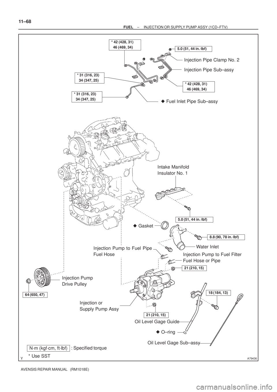
5.0 (51, 44 in.�lbf)
* 42 (428, 31)
46 (469, 34)
* 31 (316, 23)
34 (347, 25)
* 31 (316, 23)
34 (347, 25)
Injection Pipe Clamp No. 2
Injection Pipe Sub±assy
� Fuel Inlet Pipe Sub±assy
64 (650, 47)
Injection Pump
Drive Pulley
� O±ring Oil Level Gage Guide
: Specified torqueN´m (kgf´cm, ft´lbf)
* Use SST
18 (184, 13)
Oil Level Gage Sub±assy Injection or
Supply Pump Assy
21 (210, 15)
21 (210, 15)
Water Inlet
8.8 (90, 78 in.�lbf)
� Gasket
5.0 (51, 44 in.�lbf)
Intake Manifold
Insulator No. 1
* 42 (428, 31)
46 (469, 34)
Injection Pump to Fuel Filter
Fuel Hose or Pipe
Injection Pump to Fuel Pipe
Fuel Hose
11±68
± FUELINJECTION OR SUPPLY PUMP ASSY (1CD±FTV)
AVENSIS REPAIR MANUAL (RM1018E)
Page 1920 of 5135

AVENSIS REPAIR MANUAL (RM1018E)
REPLACEMENT
HINT:
Each injector assembly has a characteristic fuel injecting behavior. The ECM stores comp")
110U8±01
A79143
SST
11±60
±
FUEL INJECTOR ASSY(1CD±FTV)
AVENSIS REPAIR MANUAL (RM1018E)
REPLACEMENT
HINT:
Each injector assembly has a characteristic fuel injecting behavior. The ECM stores compensation codes
which are used to optimize fuel injection for the injectors. When replacing t\
he injector assembly, a compensa-
tion code for the new injector assembly must be set to the ECM.
1.REMOVE VACUUM RESERVOIR SUB±ASSY
(a)Disconnect the 2 vacuum hoses and the connector.
(b)Remove the 2 bolts and the vacuum reservoir.
2.REMOVE RADIATOR SUPPORT OPENING COVER
3.REMOVE ENGINE COVER NO.1
(a)Remove the 5 nuts and the engine cover.
4.REMOVE AIR CLEANER ASSY
(a)Disconnect the connector.
(b)Remove the air cleaner cap with the air cleaner hose.
(c)Remove the air cleaner filter element.
(d)Remove the 3 bolts and the air cleaner case.
5.REMOVE AIR TUBE NO.1 (See page 14±270) 6. REMOVE INJECTION PIPE SUB±ASSY NO.1
(a) Remove the 2 nuts and 2 upper infection pipe clampsfrom the intake manifold.
(b) Using SST, remove the injection pipe from the common rail side.
SST 09023±12700
(c) Using SST, remove the injection pipe from the injector side.
SST 09023±12700
(d) After removing the fuel pipe, to prevent dust or foreign ob- jects from being introduced, cover the common rail with
vinyl tape and protect the injector inlet with a vinyl or plas-
tic bag.
7. REMOVE INJECTION PIPE SUB±ASSY NO.2
SST 09023±12700
HINT:
Perform the same procedures as injection pipe No. 1.
8. REMOVE INJECTION PIPE SUB±ASSY NO.3 SST 09023±12700
HINT:
Perform the same procedures as injection pipe No. 1.
9. REMOVE INJECTION PIPE SUB±ASSY NO.4 SST 09023±12700
HINT:
Perform the same procedures as injection pipe No. 1.
10. REMOVE TIMING BELT NO.2 COVER
(a) Remove the 7 bolts and 7 seal washers, then remove the timing belt cover\
.
Page 1986 of 5135

14±1
AVENSIS REPAIR MANUAL (RM1018E)
ENGINE(1ZZ±FE/3ZZ±FE)
INSPECTION
1.INSPECT COOLANT (See page 16±1)
2.INSPECT ENGINE")
140KR±02
A62199
TCCG
A62200
±
ENGINE MECHANICAL ENGINE(1ZZ±FE/3ZZ±FE)
14±1
AVENSIS REPAIR MANUAL (RM1018E)
ENGINE(1ZZ±FE/3ZZ±FE)
INSPECTION
1.INSPECT COOLANT (See page 16±1)
2.INSPECT ENGINE OIL (See page 17±1)
3.INSPECT BATTERY (See page 19±5)
4.INSPECT AIR CLEANER FILTER ELEMENT SUB±ASSY
5.INSPECT SPARK PLUG (See page 18±3)
6.INSPECT FAN AND GENERATOR V BELT
HINT:
You don't need to check the belt deflection because auto tensioner is ado\
pted.
7.INSPECT IGNITION TIMING
(a)Warm up engine.
(b)When using hand±held tester:
(1)Connect the hand±held tester to the DLC3.
(2)Enter DATA LIST MODE on the hand±held tester.
Ignition timing: 8 to 12 �BTDC
HINT:
Please refer to the hand±held tester operator's manual if you
need help to select DATA LIST.
(c) When not using hand±held tester: (1) Using SST, connect terminal 13 (TC) and 4 (CG) ofthe DLC3.
SST 09843±18040
NOTICE:
�Make sure of the terminal numbers before connecting
them. Connection with a wrong terminal can damage
the engine.
�Turn OFF all electrical systems before connecting the
terminals.
�Operate the inspection after the cooling fan motor is
turned OFF
(2) Remove the 2 nuts, and 2 clips, and then remove the cylinder head cover.
(3) Pull out the wire harness as shown in the illustration.
(4) Connect the clip of the timing light to the engine.
NOTICE:
�Use a timing light which detects the first signal.
�After checking, be sure to wrap the wire harness with
tape.
Page 1989 of 5135
14±4
± ENGINE MECHANICALENGINE (1ZZ±FE/3ZZ±FE)
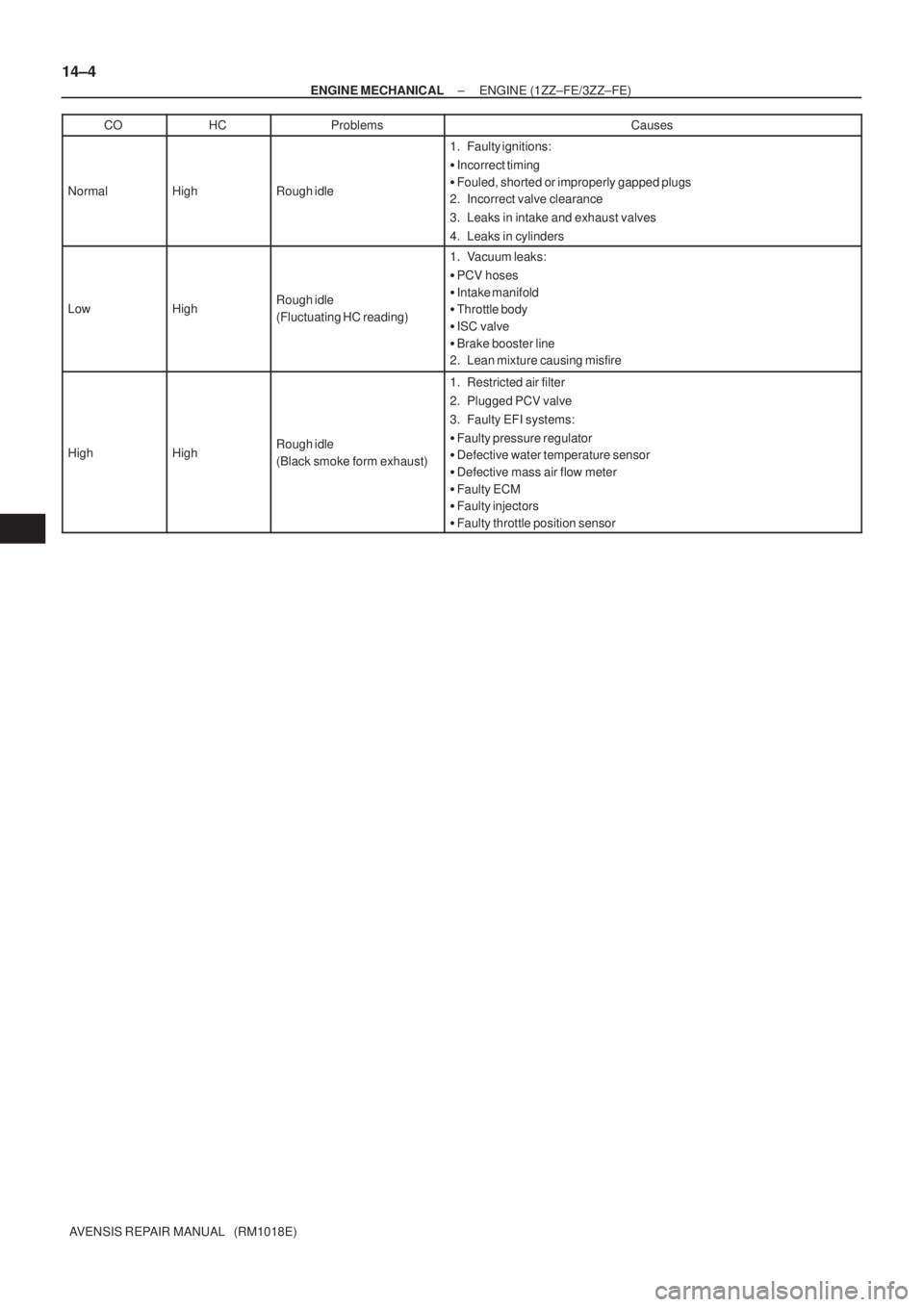
AVENSIS REPAIR MANUAL (RM1018E)CO
HCProblemsCauses
NormalHighRough idle
1. Faulty ignitions:
�Incorrect timing
�Fouled, shorted or improperly gapped plugs
2. Incorrect valve clearance
3. Leaks in intake and exhaust valves
4. Leaks in cylinders
LowHighRough idle
(Fluctuating HC reading)
1. Vacuum leaks:
�PCV hoses
�Intake manifold
�Throttle body
�ISC valve
�Brake booster line
2. Lean mixture causing misfire
HighHighRough idle
(Black smoke form exhaust)
1. Restricted air filter
2. Plugged PCV valve
3. Faulty EFI systems:
�Faulty pressure regulator
�Defective water temperature sensor
�Defective mass air flow meter
�Faulty ECM
�Faulty injectors
�Faulty throttle position sensor
Page 1992 of 5135
1306Z±01
A79155
A80093
A79158
±
INTAKE TURBOCHARGER SUB±ASSY(1CD±FTV)
13±11
AVENSIS REPAIR MANUAL (RM1018E)
REPLACEMENT
1.REMOVE ENGINE UNDER COVER SUB±ASSY NO.1
2.DRAIN ENGINE COOLANT(See page 16±44)
3.REMOVE RADIATOR SUPPORT OPENING COVER
4.REMOVE ENGINE COVER NO.1
(a)Remove the 5 nuts and the engine cover.
5.REMOVE VACUUM RESERVOIR SUB±ASSY
(a)Disconnect the 2 vacuum hoses and the connector.
(b)Remove the 2 bolts and the vacuum reservoir.
6.REMOVE AIR CLEANER ASSY
(a)Disconnect the PCV hose and the connector.
(b)Remove the air cleaner cap with the air cleaner hose.
(c)Remove the air cleaner filter element.
(d)Remove the 3 bolts and the air cleaner case. 7.REMOVE INTERCOOLER AIR HOSE
(a)Remove the 3 bolts and nut, separate the air tube No.1.
(b)Loosen the hose clamp bolts and remove the air hoseNo.1.
8.REMOVE FUEL FILTER ASSY(See page 11±82) 9. SEPARATE HEATER PUMP ASSY (W/ COLD AREA)
(a) Remove the nut and disconnect the connector.
(b) Separate the heater pump.
Page 1997 of 5135

AVENSIS REPAIR MANUAL (RM1018E)
(b)Install a new gasket and the manifold converter, and tem- porarily tighten bolt")
������������A80106
A
A
B
B
A79163
13±16
±
INTAKE TURBOCHARGER SUB±ASSY(1CD±FTV)
AVENSIS REPAIR MANUAL (RM1018E)
(b)Install a new gasket and the manifold converter, and tem- porarily tighten bolts A and bolts B while pushing the up-
per portion of the converter toward the turbocharger.
Torque: 8.0 N �m (82 kgf �cm, 71 in. �lbf)
(c)Tighten the 3 nuts. Torque: 25 N �m (255 kgf �cm, 18 ft �lbf)
(d)Tighten bolts A.
Torque: 61 N �m (622 kgf �cm, 45 ft �lbf)
(e)Tighten bolts B. Torque: 61 N �m (622 kgf �cm, 45 ft �lbf)
31.INSTALL MANIFOLD STAY NO.2
(a)Install the manifold stay No. 2, and temporarily tighten the bolt.
(b)Temporarily tighten the nut while pushing the manifold stay No. 2 toward the cylinder head.
Torque: 8.0 N �m (82 kgf �cm, 71 in. �lbf)
HINT:
No clearance between the stay and the cylinder head should be
confirmed.
(c)Tighten the bolt. Torque: 56 N �m (571 kgf �cm, 41 ft �lbf)
(d)Tighten the nut. Torque: 56 N �m (571 kgf �cm, 41 ft �lbf)
32.INSTALL EXHAUST MANIFOLD HEAT INSULATOR NO.2
Torque: 12 N �m (122 kgf �cm, 8.9 ft �lbf)
33.INSTALL TURBO INSULATOR NO.1 Torque: 20 N �m (204 kgf �cm, 15 ft �lbf)
34.INSTALL TURBO INSULATOR NO.2
Torque: 20 N �m (204 kgf �cm, 15 ft �lbf)
35.INSTALL EXHAUST PIPE ASSY (W/ COLD AREA) Torque: 7.5 N �m (76 kgf �cm, 66 in. �lbf)
36.INSTALL EXHAUST PIPE ASSY FRONT(See page 15±10)
37.INSTALL FLOOR PANEL BRACE FRONT(See page 15±10)
38. INSTALL HEATER BRACKET (W/ COLD AREA) Torque: 7.5 N �m (76 kgf �cm, 66 in. �lbf)
39. INSTALL HEATER PUMP ASSY (W/ COLD AREA) Torque: 7.5 N �m (76 kgf �cm, 66 in. �lbf)
40.INSTALL FUEL FILTER ASSY(See page 11±82)
Page 2000 of 5135
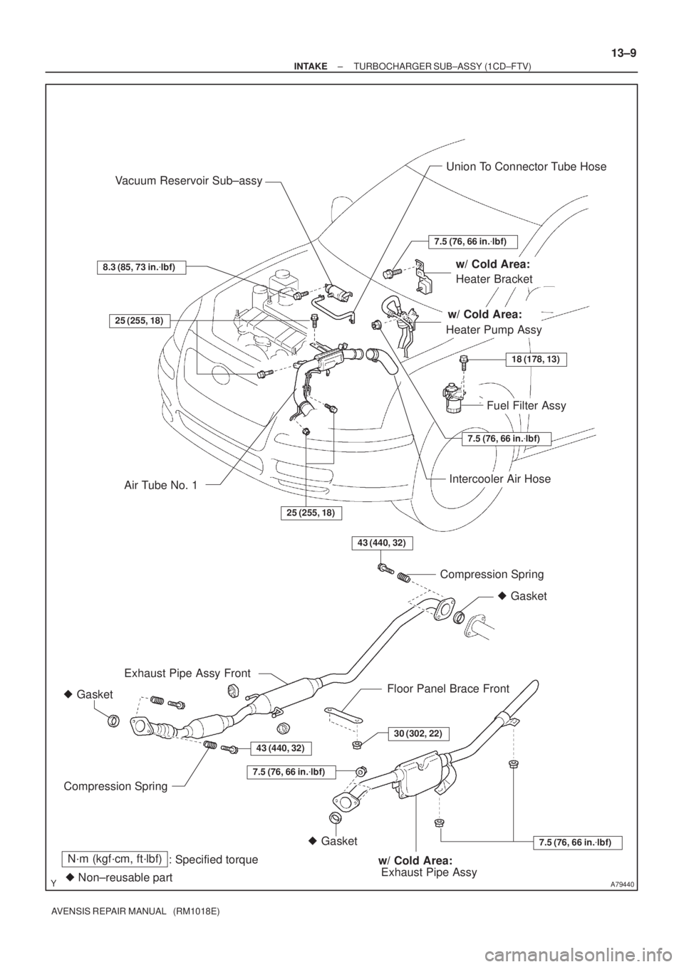
A79440
Union To Connector Tube Hose
Fuel Filter Assy Vacuum Reservoir Sub±assy
43 (440, 32)
43 (440, 32)
� Gasket
� GasketCompression Spring
Floor Panel Brace Front Exhaust Pipe Assy Front
Compression Spring
N´m (kgf´cm, ft´lbf)
: Specified torque
� Non±reusable part
Intercooler Air Hose
� Gasket
7.5 (76, 66 in.�lbf)
Exhaust Pipe Assy
30 (302, 22)
7.5 (76, 66 in.�lbf)
Heater Bracket
Heater Pump Assy25 (255, 18)
25 (255, 18)
7.5 (76, 66 in.�lbf)
18 (178, 13)
7.5 (76, 66 in.�lbf)
w/ Cold Area:
w/ Cold Area:
w/ Cold Area:
8.3 (85, 73 in.�lbf)
Air Tube No. 1
± INTAKETURBOCHARGER SUB±ASSY (1CD±FTV)
13±9
AVENSIS REPAIR MANUAL (RM1018E)
Page 2002 of 5135
13030±02
A60591
A60592
A60593
Air
E
G
A60594
Air
Filter
Battery E
± INTAKETURBO CHARGER SYSTEM (1CD±FTV)
13±7
AVENSIS REPAIR MANUAL (RM1018E)
INSPECTION
1. VACUUM SWITCHING VALVE ASSY NO.1
(a) Inspect VSV for open circuit.
(1) Using an ohmmeter, check that the there is continu-
ity between the terminals.
Resistance: 37 ± 44 � at 20�C (68�F)
(b) Inspect VSV for ground.
(1) Using an ohmmeter, check that there is no continu-
ity between each terminal and the body.
Specified condition: No continuity
(c) Inspect VSV operation.
(1) Check that air flows from port E to G.
(2) Apply battery voltage across the terminals.
(3) Check that air flows from port E to filter.

13±11
AVENSIS REPAIR MANUAL (RM1018E)
REPLACEMENT
1.REMOVE ENGINE UNDER COVER SUB±ASSY NO.1
2.DRAIN ENGINE COOLANT(See pag")

13±7
AVENSIS REPAIR MANUAL (RM1018E)
INSPECTION
1. VACUUM SWITCHING VALVE ASSY NO.1
(a) I")