Page 2007 of 5135
1306S±02
A79032
Filter
AB
A59586
13±2
± INTAKEINTAKE AIR CONTROL SYSTEM (1AZ±FSE)
AVENSIS REPAIR MANUAL (RM1018E)
INSPECTION
1. INSPECT INTAKE AIR CONTROL VALVE ASSY
(a) With 34.7 kPa (260 mm Hg, 10.2 in. Hg) of vacuum ap-
plied to the actuator, check that the actuator rod moves.
(b) One minute after applying the vacuum, check that the ac-
tuator rod does not return.
(c) If the operation is not as specified, replace the intake air
control valve assembly.
NOTICE:
Do not touch the adjust screw.
2. INSPECT VACUUM SWITCHING VALVE ASSY NO.1
(a) Using an ohmmeter, measure resistance between each
terminal.
Resistance: 33 to 39 � at 20�C (68�F)
(b) Check that air flows form port B to the filter.
(c) Apply battery voltage across the terminals.
(d) Check that air flows from port B to port A.
Page 2044 of 5135

AVENSIS REPAIR MANUAL (RM1018E)
7.REMOVE ENGINE UNDER COVER RH
(a)Remove the 6 screws and 3 clips, then detach the engi")
A78516
A78459
14±28
±
ENGINE MECHANICAL PARTIAL ENGINE ASSY(1ZZ±FE/3ZZ±FE)
AVENSIS REPAIR MANUAL (RM1018E)
7.REMOVE ENGINE UNDER COVER RH
(a)Remove the 6 screws and 3 clips, then detach the engine under cover.
8.DRAIN ENGINE COOLANT(See page 16±7)
9. DRAIN ENGINE OIL
(a) Install a new gasket and the drain plug after draining engine oil. Torque: 37 N �m (377 kgf �cm, 27 ft �lbf)
10.DRAIN MANUAL TRANSAXLE OIL (M/T TRANSAXLE) (See page 41±15)
11.DRAIN AUTOMATIC TRANSAXLE FLUID (A/T TRANSAXLE) (See page 40±42)
12. REMOVE CYLINDER HEAD COVER NO.2
(a) Remove the 2 nuts and 2 clips, then detach cylinder headcover No.2.
13.REMOVE AIR CLEANER ASSEMBLY WITH HOSE (See page 10±9 or 10±15)
14. REMOVE AIR CLEANER FILTER ELEMENT SUB±ASSY
15. REMOVE AIR CLEANER CASE SUB±ASSY
(a) Remove the 3 bolts and the air cleaner case.
16. DISCONNECT RADIATOR HOSE INLET
(a) Disconnect the radiator hose inlet from the radiator.
17. DISCONNECT RADIATOR HOSE OUTLET
(a) Disconnect the radiator hose outlet from the radiator.
18. DISCONNECT OIL COOLER INLET TUBE NO.1 (A/T TRANSAXLE)
(a) Disconnect the oil cooler inlet tube from the radiator.
19. DISCONNECT OIL COOLER OUTLET TUBE NO.1 (A/T TRANSAXLE)
(a) Disconnect the oil cooler outlet tube from the radiator.
Page 2062 of 5135
A76702
Accelerator Control Cable Assy
Heater Inlet Water Hose
Fuel Pipe Clamp
Fuel Tube Sub±assy
Heater Outlet Water Hose
Air Cleaner Cap
W/ Hose
Air Cleaner Filter
Element Sub±assy
Air Cleaner Case Sub±assy Battery Clamp
Sub±assy
Battery
Battery Tray
Battery Carrier
12.8 (131, 9)
N´m (kgf´cm, ft´lbf)
: Specified torque
Union to Connector Tube Hose
Air Cleaner Clamp
Bracket
5.0 (51, 44 in.�lbf)
Fuel Vapor Feed Hose No.1
Fuel Vapor Feed Hose No.3
5.0 (51, 44 in.�lbf)
Oil Cooler
Inlet Hose
Oil Cooler
Outlet Hose
X4
VSV Connector
Mass Air Flow
Meter Connector
14±20
± ENGINE MECHANICALPARTIAL ENGINE ASSY (1ZZ±FE/3ZZ±FE)
AVENSIS REPAIR MANUAL (RM1018E)
Page 2099 of 5135

14±101
AVENSIS REPAIR MANUAL (RM1018E)
ENGINE(1AZ±FE)
INSPECTION
1.INSPECT COOLANT (See page 16±13)
2.INSPECT ENGINE OIL (See pag")
140D1±02
CG
TCA51075
A52004
±
ENGINE MECHANICAL ENGINE(1AZ±FE)
14±101
AVENSIS REPAIR MANUAL (RM1018E)
ENGINE(1AZ±FE)
INSPECTION
1.INSPECT COOLANT (See page 16±13)
2.INSPECT ENGINE OIL (See page 17±6)
3. INSPECT BATTERY
Standard specific gravity: 1.25 to 1.29 at 20 �C (68 �F)
4. INSPECT AIR CLEANER FILTER ELEMENT SUB±ASSY
5.INSPECT SPARK PLUG (See page 18±9)
6. INSPECT V±RIBBED BELT
7. INSPECT IGNITION TIMING
(a) Warm up engine.
(b) When using hand±held tester:(1) Connect the hand±held tester to the DLC3.
(2) Enter DATA LIST MODE on the hand±held tester.
Ignition timing: 8 to 12 � BTDC
HINT:
Please refer to the hand±held tester operator's manual if you
need help to select DATA LIST.
(c) When not using hand±held tester:
(1) Using SST, connect terminals 13 (TC) and 4 (CG)of DLC3.
SST 09843±18040
NOTICE:
�Make sure of the terminal numbers before connecting
them. Connection with a wrong terminal can damage
the engine.
�Turn OFF all electrical systems before connecting the
terminals.
�Operate the inspection after the cooling fan motor is
turned OFF.
(2) Remove the cylinder head cover No.2.
(3) Pull out the wire harness as shown in the illustration.
Connect the clip of the timing light to the engine.
NOTICE:
�Use a timing light which detects the first signal.
�After checking, be sure to wrap the wire harness with
tape.
(4) Inspect ignition timing at idle.
Ignition timing: 8 to 12 � BTDC
NOTICE:
When checking the ignition timing, shift the transmission
to the neutral position.
HINT:
Run the engine at 1,000 to 1,300 rpm for 5 seconds, check that
the engine rpm returns to the idle speed.
Page 2102 of 5135
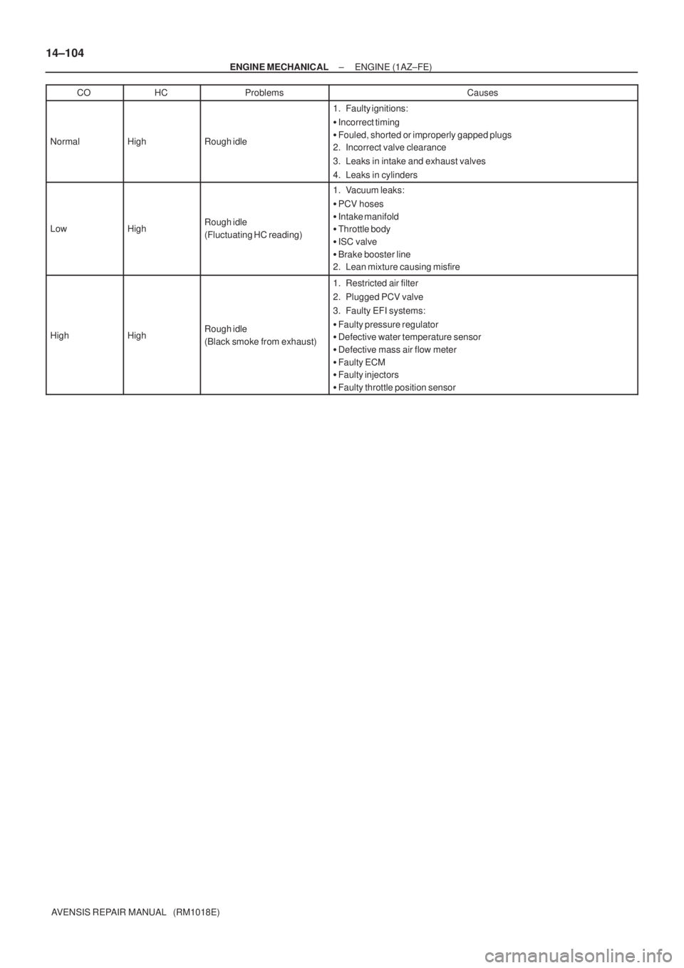
14±104
± ENGINE MECHANICALENGINE (1AZ±FE)
AVENSIS REPAIR MANUAL (RM1018E)CO
HCProblemsCauses
NormalHighRough idle
1. Faulty ignitions:
�Incorrect timing
�Fouled, shorted or improperly gapped plugs
2. Incorrect valve clearance
3. Leaks in intake and exhaust valves
4. Leaks in cylinders
LowHighRough idle
(Fluctuating HC reading)
1. Vacuum leaks:
�PCV hoses
�Intake manifold
�Throttle body
�ISC valve
�Brake booster line
2. Lean mixture causing misfire
HighHighRough idle
(Black smoke from exhaust)
1. Restricted air filter
2. Plugged PCV valve
3. Faulty EFI systems:
�Faulty pressure regulator
�Defective water temperature sensor
�Defective mass air flow meter
�Faulty ECM
�Faulty injectors
�Faulty throttle position sensor
Page 2128 of 5135

14±181
AVENSIS REPAIR MANUAL (RM1018E)
ENGINE(1AZ±FSE)
INSPECTION
1.INSPECT COOLANT (See page 16±25)
2.INSPECT ENGINE OIL(See pa")
141CP±01
CG
TCA51075
A79034
±
ENGINE MECHANICAL ENGINE(1AZ±FSE)
14±181
AVENSIS REPAIR MANUAL (RM1018E)
ENGINE(1AZ±FSE)
INSPECTION
1.INSPECT COOLANT (See page 16±25)
2.INSPECT ENGINE OIL(See page 17±13)
3.INSPECT BATTERY
Standard specific gravity: 1.25 to 1.29 at 20 �C (68 �F)
4.INSPECT AIR CLEANER FILTER ELEMENT SUB±ASSY
5.INSPECT SPARK PLUG (See page 18±14)
6.INSPECT V±RIBBED BELT
7.INSPECT IGNITION TIMING
(a)Warm up engine.
(b)When using hand±held tester:(1)Connect the hand±held tester to the DLC3.
(2)Enter DATA LIST MODE on the hand±held tester.
Ignition timing: 8 to 12 � BTDC
HINT:
Please refer to the hand±held tester operator's manual if you
need help to select DATA LIST.
(c) When not using hand±held tester:
(1) Using SST, connect terminals 13 (TC) and 4 (CG)of DLC3.
SST 09843±18040, 09843±18020
NOTICE:
�Make sure of the terminal numbers before connecting
them. Connection with a wrong terminal can damage
the engine.
�Turn OFF all electrical systems before connecting the
terminals.
�Operate the inspection after the cooling fan motor is
turned OFF
(2) Remove the cylinder head cover No.2.
(3) Pull out the wire harness as shown in the illustration.
Connect the clip of the timing light to the engine.
NOTICE:
�Use a timing light which detects the first signal.
�After checking, be sure to wrap the wire harness with
tape.
(4) Inspect ignition timing at idle.
Ignition timing: 8 to 12 � BTDC
NOTICE:
When checking the ignition timing, shift the transmission
to the neutral position.
HINT:
Run the engine at 1,000 to 1,300 rpm for 5 seconds, check that
the engine rpm returns to the idle speed. (5) Disconnect terminals 13 (TC) and 4 (CG) of DLC3.
Page 2131 of 5135
14±184
± ENGINE MECHANICALENGINE (1AZ±FSE)
AVENSIS REPAIR MANUAL (RM1018E)CO
HCProblemsCauses
NormalHighRough idle
1. Faulty ignitions:
�Incorrect timing
�Fouled, shorted or improperly gapped plugs
2. Incorrect valve clearance
3. Leaks in intake and exhaust valves
4. Leaks in cylinders
LowHighRough idle
(Fluctuating HC reading)
1. Vacuum leaks:
�PCV hoses
�Intake manifold
�Throttle body
�ISC valve
�Brake booster line
2. Lean mixture causing misfire
HighHighRough idle
(Black smoke from exhaust)
1. Restricted air filter
2. Plugged PCV valve
3. Faulty EFI systems:
�Faulty pressure regulator
�Defective water temperature sensor
�Defective mass air flow meter
�Faulty ECM
�Faulty injectors
�Faulty throttle position sensor
Page 2234 of 5135
A79418N´m (kgf´cm, ft´lbf)
: Specified torque
25 (255, 18)
18 (178, 13)
Injector Driver
Air Tube No. 2Union To Connector Tube Hose
Fuel Filter AssyHeater Inlet Water Hose Heater Outlet Water Hose Vacuum Reservoir Sub±assy
8.3 (85, 73 in.�lbf)
5.0 (51, 44 in.�lbf)
14±278
± ENGINE MECHANICALPARTIAL ENGINE ASSY (1CD±FTV)
AVENSIS REPAIR MANUAL (RM1018E)

AVENSIS REPAIR MANUAL (RM1018E)
INSPECTION
1. INSPECT INTAKE AIR CONTROL VALVE ASSY
(a) With 34.7 kPa (260 mm Hg")


: Specified torque
25 (255, 18)
18 (178, 13)
Injector Driver
Air Tube No. 2Union To Connector Tube Hose
Fuel Filter AssyHeater Inlet Water Hose Heater Outlet Water Hose V")