Page 2900 of 5135

550Z8±01
������I37091
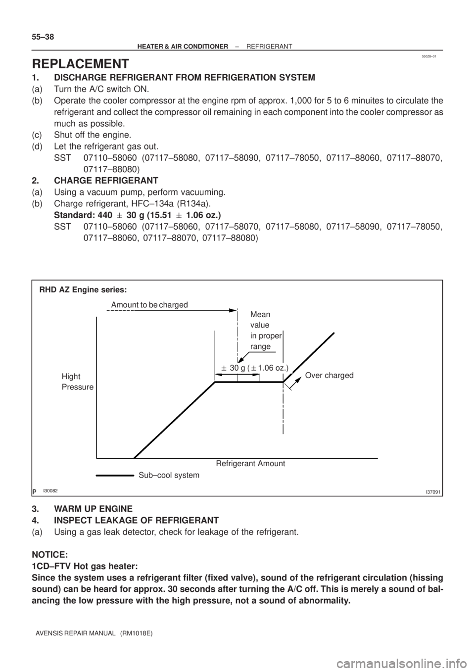
Over charged Mean
value
in proper
range
Hight
Pressure
Refrigerant Amount� 30 g (�1.06 oz.) Amount to be charged
Sub±cool system RHD AZ Engine series: 55±38
± HEATER & AIR CONDITIONERREFRIGERANT
AVENSIS REPAIR MANUAL (RM1018E)
REPLACEMENT
1. DISCHARGE REFRIGERANT FROM REFRIGERATION SYSTEM
(a) Turn the A/C switch ON.
(b) Operate the cooler compressor at the engine rpm of approx. 1,000 for 5 to 6 minuites to circulate the
refrigerant and collect the compressor oil remaining in each component into the cooler compressor as
much as possible.
(c) Shut off the engine.
(d) Let the refrigerant gas out.
SST 07110±58060 (07117±58080, 07117±58090, 07117±78050, 07117±88060, 07117±88070,
07117±88080)
2. CHARGE REFRIGERANT
(a) Using a vacuum pump, perform vacuuming.
(b) Charge refrigerant, HFC±134a (R134a).
Standard: 440 � 30 g (15.51 � 1.06 oz.)
SST 07110±58060 (07117±58060, 07117±58070, 07117±58080, 07117±58090, 07117±78050,
07117±88060, 07117±88070, 07117±88080)
3. WARM UP ENGINE
4. INSPECT LEAKAGE OF REFRIGERANT
(a) Using a gas leak detector, check for leakage of the refrigerant.
NOTICE:
1CD±FTV Hot gas heater:
Since the system uses a refrigerant filter (fixed valve), sound of the refrigerant circulation (hissing
sound) can be heard for approx. 30 seconds after turning the A/C off. This is merely a sound of bal-
ancing the low pressure with the high pressure, not a sound of abnormality.
Page 2910 of 5135
E65563
I22117
Condition
: Air conditioning system periodically repeats proper and improper function.
± HEATER & AIR CONDITIONERREFRIGERANT
55±33
AVENSIS REPAIR MANUAL (RM1018E)
(1) When the refrigerant volume is proper:
Gauge reading:
Low pressure side:
0.28 ± 0.4 MPa (2.8 ± 4.0 kgf/cm
2)
High pressure side:
1.3 ± 1.6 MPa (13 ± 16 kgf/cm
2)
(2) When there is moisture in the refrigeration system:
SymptomProbable causeDiagnosisRemedy
During operation, pressure on low
pressure side cycles between nor-
mal and vacuum
Moisture in refrigeration system
freezes at refrigerant filter orifice,
causing a temporary stop of cycle.
However, when it melts, normal
state is restored� Drier is overly saturated
� Moisture in refrigeration system
freezes at refrigerant filter orifice
and blocks circulation of refriger-
ant(1) Replace cooler drier
(2) Remove moisture in cycle by
repeatedly vacuuming
(3) Supply proper amount of new
refrigerant
Page 2912 of 5135

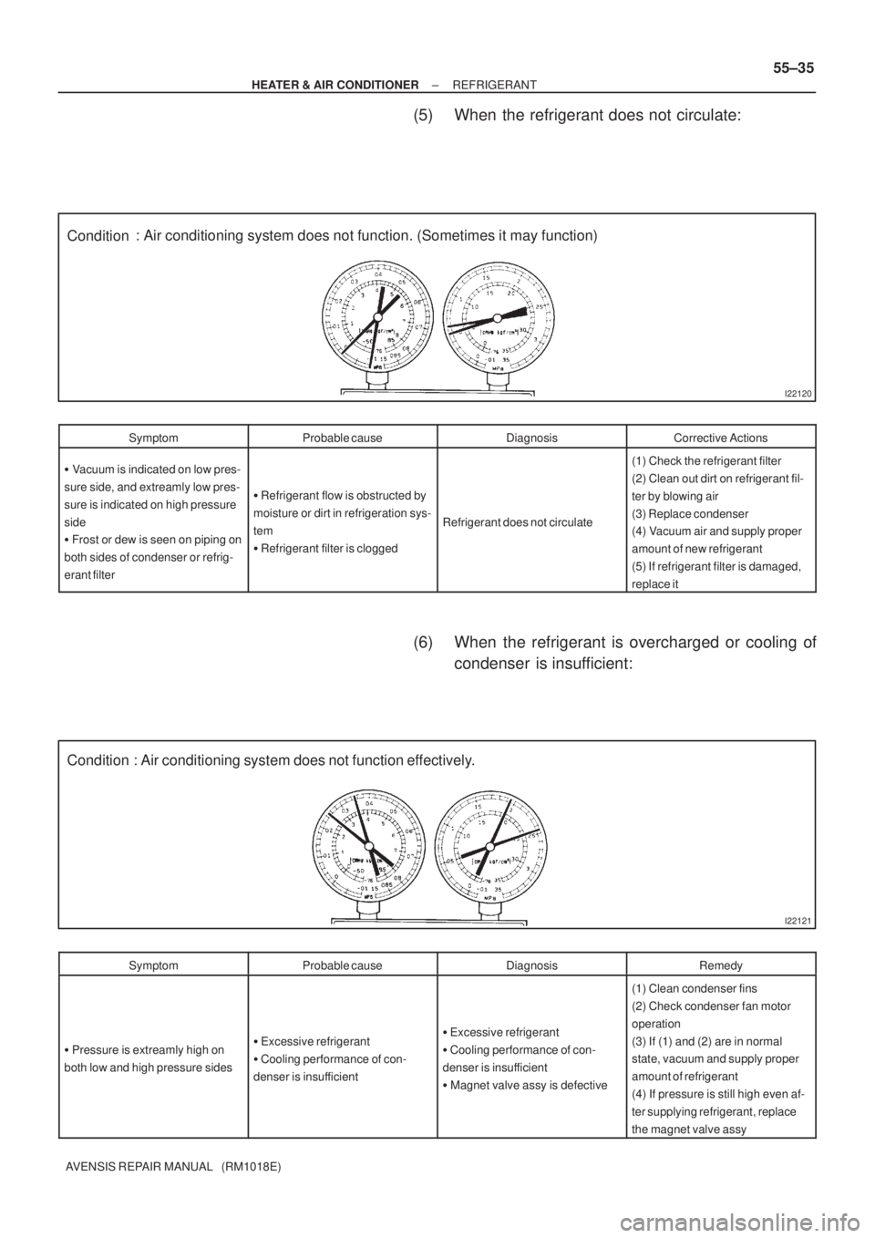
I22120
Condition: Air conditioning system does not function. (Sometimes it may function)
I22121
Condition : Air conditioning system does not function effectively.
± HEATER & AIR CONDITIONERREFRIGERANT
55±35
AVENSIS REPAIR MANUAL (RM1018E)
(5) When the refrigerant does not circulate:
SymptomProbable causeDiagnosisCorrective Actions
� Vacuum is indicated on low pres-
sure side, and extreamly low pres-
sure is indicated on high pressure
side
� Frost or dew is seen on piping on
both sides of condenser or refrig-
erant filter
� Refrigerant flow is obstructed by
moisture or dirt in refrigeration sys-
tem
� Refrigerant filter is clogged
Refrigerant does not circulate
(1) Check the refrigerant filter
(2) Clean out dirt on refrigerant fil-
ter by blowing air
(3) Replace condenser
(4) Vacuum air and supply proper
amount of new refrigerant
(5) If refrigerant filter is damaged,
replace it
(6) When the refrigerant is overcharged or cooling of
condenser is insufficient:
SymptomProbable causeDiagnosisRemedy
� Pressure is extreamly high on
both low and high pressure sides� Excessive refrigerant
� Cooling performance of con-
denser is insufficient� Excessive refrigerant
� Cooling performance of con-
denser is insufficient
� Magnet valve assy is defective
(1) Clean condenser fins
(2) Check condenser fan motor
operation
(3) If (1) and (2) are in normal
state, vacuum and supply proper
amount of refrigerant
(4) If pressure is still high even af-
ter supplying refrigerant, replace
the magnet valve assy
Page 2913 of 5135
I22122
Condition
NOTE : These gauge indica-
tions occur when the refrigera-
tion system opens and the re-
frigerant is charged without
vacuuming. : Air conditioning system does not function.
I22123
Condition : Air conditioning system does not function effectively. 55±36
± HEATER & AIR CONDITIONERREFRIGERANT
AVENSIS REPAIR MANUAL (RM1018E)
(7) When there is air in the refrigeration system:
SymptomProbable causeDiagnosisCorrective Actions
Pressure is extreamly high on both
low and the high pressure sidesAir in refrigeration system
� There is air in refrigeration sys-
tem
� Vacuuming is insufficient(1) Check if compressor oil is dirty
or insufficient
(2) Vacuum air and supply new re-
frigerant
(8) When the refrigerant filter is defective:
SymptomProbable causeDiagnosisCorrective Actions
� Pressure is extreamly high on
low pressure side
� Pressure is extreamly high on
high pressure side
Trouble with refrigerant filterExcessive refrigerantReplace refrigerant filter
Page 2955 of 5135
I353162 Claws
I35318
I35319Clamp
I35320
55±66
± HEATER & AIR CONDITIONERBLOWER ASSY
AVENSIS REPAIR MANUAL (RM1018E)
5. REMOVE AIR FILTER CASE
(a) Release the 2 claw fittings and remove the air filter case.
6. REMOVE AIR FILTER
7. REMOVE RECIRCULATION DAMPER SERVO
SUB±ASSY
(a) Remove the 2 screws and the recirculation damper servo
sub±assy.
8. REMOVE AIR CONDITIONING WIRENO1 (MANUAL
AIR CONDITIONING)
(a) Disconnect the connector.
(b) Release the clump and remove the air conditioning wire
No.1.
9. REMOVE COOLER WIRING NO.1 (AUTO AIR CONDITIONING)
HINT:
Disconnection of the cooler wiring No.1 is the same as the air conditioning wire No.1.
10. REMOVE BLOWER RESISTOR (MANUAL AIR
CONDITIONING)
(a) Remove the 2 screws and the blower resistor.
Page 2956 of 5135
I35321
I35322
I35317
I36813
I35314
± HEATER & AIR CONDITIONERBLOWER ASSY
55±67
AVENSIS REPAIR MANUAL (RM1018E)
11. REMOVE BLOWER MOTOR CONTROL (AUTO AIR
CONDITIONING)
(a) Remove the 2 screws and the blower motor control.
12. REMOVE BLOWER W/FAN MOTOR SUB±ASSY
(a) Remove the 3 screws and the blower w/ fun motor sub±
assy.
13. INSTALL AIR FILTER
(a) Install the air filter as shown in the illustration.
14. INSTALL BLOWER ASSY
(a) Install the blower assy with the claw fitting.
(b) Install the blower assy with the 2 bolts and the 2 screws.
Torque: 9.8 N�m (100 kgf�cm, 87 in.�lbf) (Bolt)
(c) Install the 2 nuts.
(d) Connect the connectors.
Page 2958 of 5135
550YQ±01
I35277
Blower Assy
Air Duct No.2
Recirculation Damper Servo Sub±assy
Air Filter
Air Filter Case
Blower w/ fan Motor Sub±assy
Manual A/C:
Blower Resistor Air Conditioning Wire No.1
Auto A/C:
Blower Motor Control
9.8 (100, 87 in.�lbf)
Cooler Wiring No.1Manual A/C:
N�m (kgf�cm, ft�lbf): Specified torque
55±64
± HEATER & AIR CONDITIONERBLOWER ASSY
AVENSIS REPAIR MANUAL (RM1018E)
BLOWER ASSY
COMPONENTS
Page 2997 of 5135
550YS±01
I35345Claw
I35346
I35347
I35348
55±100
±
HEATER & AIR CONDITIONER HEATER ASSY
AVENSIS REPAIR MANUAL (RM1018E)
HEATER ASSY
REPLACEMENT
1.REMOVE AIR CLEANER ASSY (See page 11±82)
2.REMOVE FUEL FILTER ASSY (See page 11±82) 3. REMOVE AIR DUCT NO.3
(a) Release the claw fitting and remove the bolt and the en-gine room relay No.2 block.
(b) Remove the clip and the air duct No.3.
4. DISCONNECT HEATER INLET WATER HOSE
(a) Using pliers, grip the claws of the clip and slide the clip to disconnect the heater inlet water hose.
HINT:
Prepare a support plate and waste to catch the leaked coolant.
5. DISCONNECT HEATER WATER INLET HOSE A
(a) Using pliers, grip the claws of the clip and slide the clip to disconnect the heater inlet water hose A.
HINT:
Prepare a support plate and waste to catch the leaked coolant.