Page 2998 of 5135
I35349
I35350
I35350
I35349
±
HEATER & AIR CONDITIONER HEATER ASSY
55±101
AVENSIS REPAIR MANUAL (RM1018E)
6. REMOVE HEATER ASSY
(a) Using pliers, grip the claws of the clip and slide the clip to
disconnect the heater fuel hose.
HINT:
Prepare a support plate and waste to catch the leaked fuel.
(b) Disconnect the connector.
(c) Remove the 2 bolts and the heater assy.
7. INSTALL HEATER ASSY
(a) Install the heater assy with the 2 bolts. Torque: 7.5 N �m (76 kgf �cm, 66 in. �lbf)
(b) Connect the connector.
(c) Install the heater fuel hose.
HINT:
Prepare a support plate and waste to catch the leaked fuel.
8.INSTALL FUEL FILTER ASSY (See page 11±82)
9.INSTALL AIR CLEANER ASSY (See page 11±82)
10.ADD ENGINE COOLANT (See page 16±44)
11.CHECK FOR ENGINE COOLANT LEAKS (See page 16±37)
12.CHECK FUEL LEAK (See page 11±56)
Page 3001 of 5135
I35341
I35342
I35343
I35344
I32993
14 mm
(0.55 in.)
Hexagon
Wrench
Modulator
± HEATER & AIR CONDITIONERW/RECEIVER CONDENSER ASSY
55±95
AVENSIS REPAIR MANUAL (RM1018E)
11. REMOVE W/RECEIVER CONDENSER ASSY
(a) Remove the bolt and the w/ receiver condenser assy.
12. REMOVE DISCHARGE TUBE (W/ HOT GAS HEATER)
(a) Remove the 2 bolts and the discharge tube.
13. REMOVE REFRIGERANT FILTER (W/ HOT GAS
HEATER)
(a) Disconnect the discharge tube and remove the refriger-
ant filter.
14. R E M O V E M A G N E T VA LV E A S S Y ( W / H O T G A S
HEATER)
(a) Remove the 4 bolts and the magnet valve assy.
15. REMOVE COOLER DRYER (W/O HOT GAS HEATER)
(a) 1AZ±FSE:
Remove the 2 bolts and bracket.
(b) Using a hexagon wrench 14 mm (0.55 in.), remove the
cap from the modulator.
Page 3003 of 5135

20. I N S TA L L M A G N E T VA LV E A S S Y ( W / H O T G A S
HEATER)
(a) Ins")
I35344
I35343
I35342
I35336
± HEATER & AIR CONDITIONERW/RECEIVER CONDENSER ASSY
55±97
AVENSIS REPAIR MANUAL (RM1018E)
20. I N S TA L L M A G N E T VA LV E A S S Y ( W / H O T G A S
HEATER)
(a) Install the magnet valve assy with the 4 bolts.
Torque: 3.4 N�m (35 kgf�cm, 30 in.�lbf)
21. INSTALL REFRIGERANT FILTER (W/ HOT GAS
HEATER)
(a) Install the refrigerant filter to the discharge tube.
22. INSTALL DISCHARGE TUBE (W/ HOT GAS HEATER)
(a) Install the discharge tube with the 2 bolts.
Torque: 5.4 N�m (55 kgf�cm, 47 in.�lbf)
23. INSTALL LIQUID TUBE SUB±ASSY B (RHD(1CD±FTV)
STEERING POSITION TYPE)
(a) Remove the attached vinyl tape from the tube and the
connecting part of the w/ receiver condenser assy.
(b) Sufficiently apply compressor oil to a new O±ring and the
fitting surface of the pipe joint.
Compressor oil: ND±OIL 8 or equivalent
(c) Install the O±ring on the liquid tube sub±assy B.
(d) Install the liquid tube sub±assy B on the w/ receiver con-
denser assy with the bolt.
Torque: 5.4 N�m (55 kgf�cm, 47 in.�lbf)
24. INSTALL DISCHARGE TUBE SUB±ASSY (W/ HOT
GAS HEATER)
(a) Remove the attached vinyl tape from the tube and the
connecting part of the w/ receiver condenser assy.
(b) Sufficiently apply compressor oil to a new 2 O±rings and
the fitting surface of the pipe joint.
Compressor oil: ND±OIL 8 or equivalent
(c) Install the O±ring on the discharge tube sub±assy.
Page 3007 of 5135
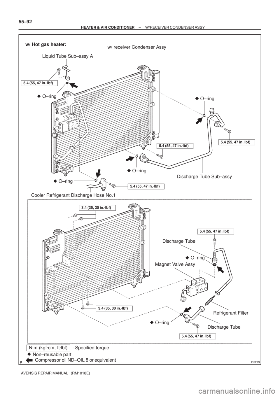
I35279
N�m (kgf�cm, ft�lbf) : Specified torque
Non±reusable part �
Compressor oil ND±OIL 8 or equivalentw/ receiver Condenser Assy
Liquid Tube Sub±assy A
Cooler Refrigerant Discharge Hose No.1O±ring �O±ring �
w/ Hot gas heater:
5.4 (55, 47 in.�lbf)
O±ring �
O±ring
�
5.4 (55, 47 in.�lbf)
O±ring �
5.4 (55, 47 in.�lbf)
5.4 (55, 47 in.�lbf)5.4 (55, 47 in.�lbf)
O±ring �
Discharge Tube Sub±assy
5.4 (55, 47 in.�lbf)
3.4 (35, 30 in.�lbf)
3.4 (35, 30 in.�lbf)
Discharge Tube
Discharge Tube
Refrigerant Filter
Magnet Valve Assy
55±92
± HEATER & AIR CONDITIONERW/RECEIVER CONDENSER ASSY
AVENSIS REPAIR MANUAL (RM1018E)
Page 3460 of 5135
 HO2S
Heated Oxygen SensorHeated Oxygen Sensor (HO2S)
IACIdle Air ControlIdle Speed Control (ISC)
IATIntake Air TemperatureIntake o")
± INTRODUCTIONTERMS
01±13
1AZ±FSE ENGINE REPAIR MANUAL (RM1019E) HO2S
Heated Oxygen SensorHeated Oxygen Sensor (HO2S)
IACIdle Air ControlIdle Speed Control (ISC)
IATIntake Air TemperatureIntake or Inlet Air Temperature
ICMIgnition Control Module±
IFIIndirect Fuel InjectionIndirect Injection (IDL)
IFSInertia Fuel±Shutoff±
ISCIdle Speed Control±
KSKnock SensorKnock Sensor
MAFMass Air FlowAir Flow Meter
MAPManifold Absolute PressureManifold Pressure Intake Vacuum
MCMixture Control
Electric Bleed Air Control Valve (EBCV)
Mixture Control Valve (MCV)
Electric Air Control Valve (EACV)
MDPManifold Differential Pressure±
MFIMultiport Fuel InjectionElectronic Fuel Injection (EFI)
MILMalfunction Indicator LampCheck Engine Lamp
MSTManifold Surface Temperature±
MVZManifold Vacuum Zone±
NVRAMNon±Volatile Random Access Memory±
O2SOxygen SensorOxygen Sensor, O2 Sensor (O2S)
OBDOn±Board DiagnosticOn±Board Diagnostic System (OBD)
OCOxidation Catalytic ConverterOxidation Catalyst Convert (OC), CCo
OPOpen LoopOpen Loop
PAIRPulsed Secondary Air InjectionAir Suction (AS)
PCMPowertrain Control Module±
PNPPark/Neutral Position±
PROMProgrammable Read Only Memory±
PSPPower Steering Pressure±
PTOXPeriodic Trap OxidizerDiesel Particulate Filter (DPF)
Diesel Particulate Trap (DPT)
RAMRandom Access MemoryRandom Access Memory (RAM)
RMRelay Module±
ROMRead Only MemoryRead Only Memory (ROM)
RPMEngine SpeedEngine Speed
SCSuperchargerSupercharger
SCBSupercharger BypassE±ABV
SFISequential Multiport Fuel InjectionElectronic Fuel Injection (EFI), Sequential Injection
SPLSmoke Puff Limiter±
SRIService Reminder Indicator±
SRTSystem Readiness Test±
STScan Tool±
TBThrottle BodyThrottle Body
TBIThrottle Body Fuel InjectionSingle Point Injection
Central Fuel Injection (Ci)
TCTurbochargerTurbocharger
TCCTorque Converter ClutchTorque Converter
Page 3513 of 5135
 ISC
Idle Speed Control±
KSKnock SensorKnock Sensor
MAFMass Air FlowAir Flow Meter
MAPManifold Absolute")
± INTRODUCTIONTERMS FOR MANUAL TRANSAXLE REPAIR MANUAL
01±7
C250 M/T REPAIR MANUAL (RM1020E) ISC
Idle Speed Control±
KSKnock SensorKnock Sensor
MAFMass Air FlowAir Flow Meter
MAPManifold Absolute PressureManifold Pressure
Intake Vacuum
MCMixture Control
Electric Bleed Air Control Valve (EBCV)
Mixture Control Valve (MCV)
Electric Air Control Valve (EACV)
MDPManifold Differential Pressure±
MFIMultiport Fuel InjectionElectronic Fuel Injection (EFI)
MILMalfunction Indicator LampCheck Engine Light
MSTManifold Surface temperature±
MVZManifold Vacuum Zone±
NVRAMNon±Volatile Random Access Memory±
O2SOxygen SensorOxygen Sensor, O2 Sensor (O2S)
OBDOn±Board DiagnosticOn±Board Diagnostic (OBD)
OCOxidation Catalytic ConverterOxidation Catalyst Converter (OC), CC0
OPOpen LoopOpen Loop
PAIRPulsed Secondary Air InjectionAir Suction (AS)
PCMPowertrain Control Module±
PNPPark/Neutral Position±
PROMProgrammable Read Only Memory±
PSPPower Steering Pressure±
PTOXPeriodic Trap OxidizerDiesel Particulate Filter (DPF)
Diesel Particulate Trap (DPT)
RAMRandom Access MemoryRandom Access Memory (RAM)
RMRelay Module±
ROMRead Only MemoryRead Only Memory (ROM)
RPMEngine SpeedEngine Speed
SCSuperchargerSupercharger
SCBSupercharger Bypass±
SFISequential Multiport Fuel InjectionElectronic Fuel Injection (EFI), Sequential Injection
SPLSmoke Puff Limiter±
SRIService Reminder Indicator±
SRTSystem Readiness Test±
STScan Tool±
TBThrottle BodyThrottle Body
TBIThrottle Body Fuel InjectionSingle Point Injection
Central Fuel Injection (Ci)
TCTurbochargerTurbocharger
TCCTorque Converter ClutchTorque Converter
TCMTransmission Control ModuleTransmission ECU (Electronic Control Unit)
TPThrottle PositionThrottle Position
TRTransmission Range±
TVVThermal Vacuum ValveBimetallic Vacuum Switching Valve (BVSV)
Thermostatic Vacuum Switching Valve (TVSV)
TWCThree±Way Catalytic ConverterThree±Way Catalytic (TWC)
CC
RO
TWC+OCThree±Way + Oxidation Catalytic ConverterCCR + CCO
VA FVolume Air FlowAir Flow Meter
VRVoltage RegulatorVoltage Regulator
VSSVehicle Speed SensorVehicle Speed Sensor (Read Switch Type)
WOTWide Open ThrottleFull Throttle
Page 3786 of 5135

14±9
1ZZ±FE,3ZZ±FE ENGINE REPAIR MANUAL
(RM923E)
(g) Remove th")
A62193
Straight Pin Fringe Bolt
A62815
Mesh
A62816
37 9 62
4 8 10 5 1
B08737
± ENGINE MECHANICALPARTIAL ENGINE ASSY (1ZZ±FE/3ZZ±FE)
14±9
1ZZ±FE,3ZZ±FE ENGINE REPAIR MANUAL
(RM923E)
(g) Remove the fringe bolt of camshaft timing gear assembly.
NOTICE:
�Be sure not to remove the other 4 bolts.
�In case of reusing the camshaft timing gear, release
the strait pin locking first, and then install the gear.
20. REMOVE CAMSHAFT TIMING OIL CONTROL VALVE ASSY
(a) Remove the bolt and camshaft timing oil control valve.
21. REMOVE OIL CONTROL VALVE FILTER
(a) Remove the bolt, gasket and oil control valve filter.
22. REMOVE CYLINDER HEAD SUB±ASSY
(a) Using a bi±hexagon wrench 10, uniformly loosen and re-
move the 10 cylinder head bolts, in several passes, in the
sequence shown. Remove the 10 cylinder head bolts and
plate washers.
NOTICE:
�Be careful not to drop washers into the cylinder head.
�Head warpage or cracking could result from remov-
ing bolts in an incorrect order.
23. REMOVE CYLINDER HEAD GASKET
(a) Remove the gasket from the cylinder block.
24. REMOVE OIL PUMP ASSY
(a) Remove the 5 bolts, oil pump and gasket.
Page 3787 of 5135

1ZZ±FE,3ZZ±FE ENGINE REPAIR MANUAL
(RM923E)
25. REMOVE OIL FILTER SUB±ASSY
(a) Using SST")
A62817SST
A62202
Cut Position
A01153
A01456
14±10
± ENGINE MECHANICALPARTIAL ENGINE ASSY (1ZZ±FE/3ZZ±FE)
1ZZ±FE,3ZZ±FE ENGINE REPAIR MANUAL
(RM923E)
25. REMOVE OIL FILTER SUB±ASSY
(a) Using SST, remove the oil filter.
SST 09228±06501
26. REMOVE OIL FILTER UNION
(a) Using a socket hexagon wrench 12, remove the oil filter union.
27. REMOVE ENGINE REAR OIL SEAL
(a) Using a knife, cut off the oil seal lip.
(b) Using a screwdriver with its tip taped, pry out the oil seal.
NOTICE:
After the removal, check if the crankshaft is not damaged.
If there is, mend it with a sandpaper (# 400).
28. REMOVE OIL PAN DRAIN PLUG
(a) Remove the oil pan drain plug and gasket from the oil pan.
29. REMOVE OIL PAN SUB±ASSY
(a) Remove the 14 bolts and 2 nuts.
(b) Insert the blade of SST between the bearing cap sub±as-
sembly and oil pan, and cut off applied sealer and remove
the oil pan.
SST 09032±00100
NOTICE:
Be careful not to damage the oil pan contact surface of the
bearing cap sub±assembly and the oil pan flange.

6. REMOVE HEATER ASSY
(a) Using pliers, grip the claws of the clip and slide the clip to
d")

Hexagon
Wrench
Modulator
± HEATER & AIR CONDITIONERW/RECEIVER CONDENSER ASSY
55±95
AVENSIS REPAIR MANUAL (RM1018E)
11. REMOVE W/RECEIVER CONDENS")