Page 4238 of 5135
−
DIAGNOSTICS SFI SYSTEM (2AZ−FSE)
05 −1 07
AVENSIS Supplement (RM 1045E)
10 CHECK WHETHER MISFIRE IS OCCURRED OR NOT BY MONITORING DTC AND
DATA LIST
NG PERFORM TROUBLESHOOTING FOR MISFIRE
(See page 05 −1 46)
OK
11 CHECK AIR INDUCTION SYSTEM
(a) Check for vacuum leaks in the air induction system.
NG REPAIR OR REPLACE AIR INDUCTION SYSTEM
OK
1 2 CHECK FUEL PRESSURE(LOW PRESSURE) (See page 11− 4)
NG CHECK AND REPLACE FUEL PUMP,
PRESSURE REGULATOR, FUEL PIPE LINE AND
FILTER
OK
1 3 CHECK FUEL PRESSURE(HIGH PRESSURE) (See page 11− 4)
NG CHECK AND REPLACE FUEL PUMP, FUEL
PRESSURE SENSOR, WIRING AND FUEL
LEAKAGE
OK
1 4 CHECK FOR EXHAUST GAS LEAKS
NG REPAIR OR REPLACE EXHAUST GAS
LEAKAGE POINT (See Page 15− 2)
OK
1 5 CONFIRM IF ANY MISFIRING DTCS WERE PRESENT AT STEP 1
(a) Misfiring DTC P0301, P0302, P0303 and/or P0304 was present at step 1.
NO REPLACE HEATED OXYGEN SENSOR
YES
Page 4326 of 5135
(From September, 2003)
05 −27 1
AVENSIS Supplement (RM 1045E)
BASIC INSPECTION
When the malfunction is not confirmed in the DTC check, troubleshoot")
05I7H−01
−
DIAGNOSTICS ECD SYSTEM (1CD −FTV)(From September, 2003)
05 −27 1
AVENSIS Supplement (RM 1045E)
BASIC INSPECTION
When the malfunction is not confirmed in the DTC check, troubleshooting should be carried out in all the
possible circuits considered as causes of the problem. In many cases, by carrying out the basic engine check
shown in the following flowchart, the location causing the problem can be found quickly and efficiently. There-
fore, using this check is essential in the engine troubleshooting.
1 CHECK BATTERY VOLTAGE
NOTICE:
Carry out this check with the engine stopped and ignition switch OFF.
OKNG
Voltage11 V or moreLess than 11 V
NG CHARGE OR REPLACE BATTERY
OK
2 CHECK IF ENGINE WILL CRANK
NG PROCEED TO PROBLEM SYMPTOMS TABLE ON PAGE 05 −282
OK
3 CHECK AIR FILTER
(a) Visually check if the air filter is not contaminated with dirt or oil. NG CLEAN OR REPLACE
OK
4 CHECK FUEL QUALITY
(a) Check that only diesel fuel is used.
(b) Check that the fuel does not contain any impurity. NG REPLACE FUEL
OK
5 CHECK ENGINE OIL (See page 17− 9)
NG ADD OR REPLACE
OK
Page 4355 of 5135
(From September, 2003)
05−513
AVENSIS Supplement (RM1045E)
3 PERFORM ENGINE RPM ACCELERATION
HINT:
If exhaust gas contain excessive black smoke, perform the foll")
− DIAGNOSTICSECD SYSTEM (1CD−FTV)(From September, 2003)
05−513
AVENSIS Supplement (RM1045E)
3 PERFORM ENGINE RPM ACCELERATION
HINT:
If exhaust gas contain excessive black smoke, perform the following steps.
(a) Accelerate the engine speed up to the maximum RPM with no load 20 times.
(b) Check the volume of the black smoke in the exhaust gas.
Result:
ResultProceed to
Black smoke is fadedOK
Black smoke remains in the exhaust gasNG
HINT:
Deposited soot in the exhaust system is a source of the excessive black smoke.
NG Go to step 4
OK
END
4 CHECK AIR INTAKE SYSTEM AND EXHAUST SYSTEM
(a) Remove the air cleaner filter.
(b) Inspect the EGR valve operation.
(1) Start the engine and warm it up.
(2) Check that a clicking sound is heard from the EGR valve when the vacuum hose is disconnected
from EGR valve with the engine in an idle.
(c) Inspect the intake shutter (throttle valve) operation.
(1) Start the engine.
(2) Check if the intake shutter fully opens when accelerating the engine speed.
HINT:
Under quick accelerating of the engine speed, the EGR valve is fully closed and the intake shutter is fully
opened. If the systems are normal, the volume of the black smoke will result in decrease.
NG Go to step 5
OK
CHECK AND REPAIR LOCATION WHERE MALFUNCTION EXIST
Page 4464 of 5135
100LY−01
A84695
Mass Air Flow
Meter Connector
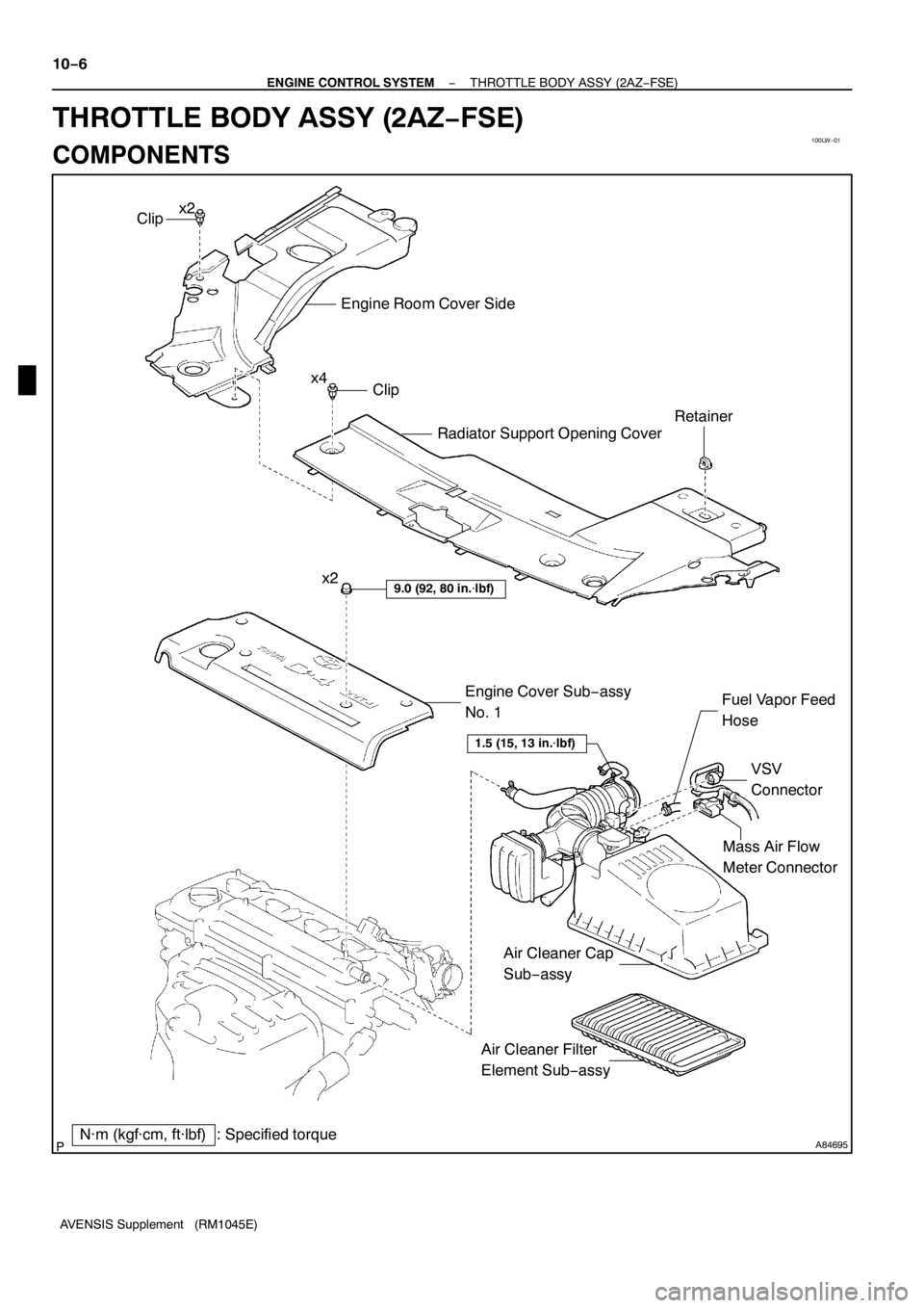
N·m (kgf·cm, ft·lbf) : Specified torqueEngine Cover Sub−assy
No. 1
9.0 (92, 80 in.�lbf)
VSV
Connector Fuel Vapor Feed
Hose
Clip
Engine Room Cover Side
Radiator Support Opening Cover
Clip
Retainer
x2
x4
1.5 (15, 13 in.�lbf)
Air Cleaner Filter
Element Sub−assy x2
Air Cleaner Cap
Sub−assy
− ENGINE CONTROL SYSTEMKNOCK SENSOR (2AZ−FSE)
10−11
AVENSIS Supplement (RM1045E)
KNOCK SENSOR (2AZ−FSE)
COMPONENTS
Page 4470 of 5135
(c)
(c)
(b)
(f)
(g)
(d)
(h)
Air Cleaner Clamp
(e)
A84698
(a)
(b)
(c)
A84699
(d)
(e)
(e)
(e)
(e)
A84700
(f)
(f)
(f)
(f)
− ENGINE CONTROL SYSTEMTHROTTLE BODY ASSY (2AZ−FSE)
10−9
AVENSIS")
A81620
(a)(c)
(c)
(b)
(f)
(g)
(d)
(h)
Air Cleaner Clamp
(e)
A84698
(a)
(b)
(c)
A84699
(d)
(e)
(e)
(e)
(e)
A84700
(f)
(f)
(f)
(f)
− ENGINE CONTROL SYSTEMTHROTTLE BODY ASSY (2AZ−FSE)
10−9
AVENSIS Supplement (RM1045E)
6. REMOVE AIR CLEANER CAP SUB−ASSY
(a) Disconnect the mass air flow meter connector.
(b) Disconnect the VSV connector.
(c) Remove the 2 wiring harness clamps.
(d) Disconnect the ventilation hose.
(e) Disconnect the fuel vapor feed hose No. 1.
(f) Disconnect the fuel vapor feed hose No. 2.
(g) Loosen the hose clamp bolt.
(h) Raise the air cleaner clamp up, then the slide it to the air
cleaner cap.
(i) Remove the air cleaner cap together with the air cleaner
hose No. 1.
(j) Remove the air cleaner filter element.
7. REMOVE THROTTLE BODY ASSY
(a) Disconnect the throttle control motor connector.
(b) Remove the bolt.
(c) Unfasten the clip, then remove the wiring harness protec-
tor.
(d) Remove the bolt, then remove the ground terminal.
(e) Remove the 4 bolts, then remove the throttle body brack-
et.
(f) Remove the 4 bolts, then remove the throttle body.
(g) Remove the gasket from the intake manifold.
Page 4472 of 5135
100LW−01
A84695
Mass Air Flow
Meter Connector
N·m (kgf·cm, ft·lbf) : Specified torqueEngine Cover Sub−assy
No. 1
9.0 (92, 80 in.�lbf)
VSV
Connector Fuel Vapor Feed
Hose
Clip
Engine Room Cover Side
Radiator Support Opening Cover
Clip
Retainer
x2
x4
1.5 (15, 13 in.�lbf)
Air Cleaner Filter
Element Sub−assy x2
Air Cleaner Cap
Sub−assy 10−6
− ENGINE CONTROL SYSTEMTHROTTLE BODY ASSY (2AZ−FSE)
AVENSIS Supplement (RM1045E)
THROTTLE BODY ASSY (2AZ−FSE)
COMPONENTS
Page 4555 of 5135
A85746
Union to Connector Tube Hose
Fuel Filter Assy Vacuum Reservoir Sub−assy
43 (440, 32)
43 (440, 32)
zGasket
zGasketCompression Spring
Floor Panel Brace Front Exhaust Pipe Assy Front
Compression Spring
N·m (kgf·cm, ft·lbf)
: Specified torque
zNon−reusable partzGasket
7.5 (76, 66 in.�lbf)
Exhaust Pipe Assy
30 (302, 22)
7.5 (76, 66 in.�lbf)
Heater Bracket
Heater Pump Assy25 (255, 18)
25 (255, 18)
7.5 (76, 66 in.�lbf)
18 (178, 13)
7.5 (76, 66 in.�lbf)
w/ Cold Area:
w/ Cold Area:
w/ Cold Area:
8.3 (85, 73 in.�lbf)
Air Tube No. 1
x2
43 (440, 32)
6.0 (61, 53 in.�lbf)
13−10− INTAKETURBOCHARGER SUB−ASSY (1CD−FTV)(From
September, 2003)
AVENSIS Supplement (RM1045E)
Page 4575 of 5135

(a)
(b)(b)
(a)
(a)
A85630
11−46
− FUELINJECTOR ASSY (1CD−FTV)(From September, 2003)
AVENSIS Supplement (RM1045E)
REPLACEMENT
NOTICE:
If an incorrect injector compensation")
1111 D−01
A93661
(a)
(a)
(b)(b)
(a)
(a)
A85630
11−46
− FUELINJECTOR ASSY (1CD−FTV)(From September, 2003)
AVENSIS Supplement (RM1045E)
REPLACEMENT
NOTICE:
If an incorrect injector compensation code was registered with the ECM, it may rattle the engine as-
sembly or the engine idling may become rough. In addition, it may become a cause of engine failure
or shorten the life of the engine.
HINT:
SIn order to optimize the injector’s fuel injection characteristic, the ECM compensates the injection dura-
tion by each cylinder. The ECM stores and uses compensating data in the form of a 30−digit−alphanu-
meric value that is imprinted on the head portion of each injector as the injector compensation code.
SIf you installed a new injector, its own injector compensation code is needed to register with the ECM.
Also, if you replaced the ECM, the compensation codes of all the injectors are needed to register be-
cause the new ECM does not have the codes until they are registered.
SOnce the ECM is replaced, DTC P1601 will be present when turning the ignition switch to ON. This
is to inform you that the injector compensation codes are required to register with the ECM. In order
to clear the DTC, register the compensation codes first, then turn the ignition switch to OFF and wait
for 30 seconds or longer.
1. REMOVE VACUUM RESERVOIR SUB−ASSY
(a) Disconnect the 2 vacuum hoses and connector.
(b) Remove the 2 bolts and vacuum reservoir.
2. REMOVE RADIATOR SUPPORT OPENING COVER
3. REMOVE ENGINE COVER SUB−ASSY NO.1
(a) Remove the 5 nuts and engine cover.
4. REMOVE AIR CLEANER ASSY
(a) Disconnect the connector.
(b) Remove the air cleaner cap together with the air cleaner hose.
(c) Remove the air cleaner filter element.
(d) Remove the 3 bolts and air cleaner case.
5. REMOVE AIR TUBE NO.1
(a) Remove the 3 bolts and nut, then separate the air tube
No. 1.
(b) Loosen the hose clamp bolts.
6. REMOVE FUEL PIPE NO.3
(a) Remove the fuel pipe insulator.

05 −1 07
AVENSIS Supplement (RM 1045E)
10 CHECK WHETHER MISFIRE IS OCCURRED OR NOT BY MONITORING DTC AND
DATA LIST
NG PERFORM TROUBLESHOOTING FOR MISFIRE
(Se")


43 (440, 32)
zGasket
zGasketCompression Spring
Floor Panel Brace Front Exhaust Pipe Assy Front
Compression")