Page 499 of 5135
A67528
OCV Signal Waveform1 msec./Division 5 V/
Division
GND
(A)(A) (A)
E11
OC1 +OC1±
±
DIAGNOSTICS SFI SYSTEM(1AZ±FSE)
05±327
AVENSIS REPAIR MANUAL (RM1018E)
4INSPECT ECM(OCV SIGNAL)
(a)Inspection using the oscilloscope.
(b)During idling, check the waveform between the terminals
of the E11 ECM connector.
Standard:
Symbols (Terminal No.)Specified condition
OC1+ (E11±16) ± OC1± (E11±15)Correct waveform is as shown
HINT:
The waveform frequency (A) is lengthened as the engine speed
becomes higher.
NGCHECK AND REPLACE ECM (See page 01±32)
OK
5 INSPECT OIL CONTROL VALVE FILTER
NG REPLACE OIL CONTROL VALVE FILTER
OK
6 INSPECT CAMSHAFT TIMING OIL CONTROL VALVE ASSY(OCV) (See page 10±39)
OK Go to step 8
NG
7 REPLACE CAMSHAFT TIMING OIL CONTROL VALVE ASSY(OCV)
GO
8INSPECT CAMSHAFT TIMING GEAR ASSY (See page 14±240)
OK Go to step 10
NG
Page 500 of 5135
05±328
±
DIAGNOSTICS SFI SYSTEM(1AZ±FSE)
AVENSIS REPAIR MANUAL (RM1018E)
9REPLACE CAMSHAFT TIMING GEAR ASSY (See page 14±240)
GO
10CHECK BLOCKAGE(OCV, OIL CHECK VALVE AND OIL HOLE)
NGREPAIR OR REPLACE
OK
11CHECK IF DTC OUTPUTS REOCCUR
(a)Clear the DTC. (1)Operating the hand±held tester to erase the codes, or disconnecting the batter\
y terminal or the
EFI and ETCS fuses for 60 seconds or more.
(b)Start the engine and warm it up.
(c)Drive the vehicle around for 10 minutes or more.
(d)Read output DTC using the hand±held tester.
Standard: No DTC output.
HINT:
*: DTCs P0011 or P0012 is output when a foreign object in engine oil is caught in so\
me part of the system.
These codes will stay registered even if the system returns to normal after a\
short time. These foreign objects
are then captured by the oil filter, thus eliminating the source of the problem.
OKVVT SYSTEM OK
NG
CHECK AND REPLACE ECM (See page 01±32)
Page 534 of 5135
(104)(140)(176) (32)(68)(212)������������
30
20
10
5
3
02040
0.1 1
0.3 0.2
0.5 2
6080100
±20
(±4)(104)(140)(176) (32)(68)(212)
A8")
������������
3020
10
5
3
02040
0.1 1
0.3 0.2
0.5 2
6080100
±20
(±4)(104)(140)(176) (32)(68)(212)������������
30
20
10
5
3
02040
0.1 1
0.3 0.2
0.5 2
6080100
±20
(±4)(104)(140)(176) (32)(68)(212)
A81700
Ohmmeter
Acceptable
TEMPERATURE �C ( �F)
RESISTANCE K �
±
DIAGNOSTICS SFI SYSTEM(1AZ±FSE)
05±399
AVENSIS REPAIR MANUAL (RM1018E)
5INSPECT ENGINE COOLANT TEMPERATURE SENSOR(RESISTANCE)
(a)Remove the engine coolant temperature sensor.
(b)Measure the resistance between the terminals.
Resistance:
2.32 to 2.59 k �at 20 �C (68 �F)
0.310 to 0.326 k �at 80 �C (176 �F)
NOTICE:
In case of checking the engine coolant temperature sensor
in the water, be careful not to allow water to go into the ter-
minals. After checking, dry the sensor.
HINT:
Alternate procedure: Connect an ohmmeter to the installed en-
gine coolant temperature sensor and read the resistance. Use
an infrared thermometer to measure the engine temperature in
the immediate vicinity of the sensor. Compare these values to
the resistance/temperature graph. Change the engine temper-
ature (warm up or allow to cool down) and repeat the test.
NGREPLACE ENGINE COOLANT TEMPERATURE SENSOR
OK
6CHECK FOR SPARK AND IGNITION (See page 18±12)
NG REPAIR OR REPLACE
OK
7CHECK FUEL PRESSURE(LOW PRESSURE) (See page 11±33)
NG CHECK AND REPLACE FUEL PUMP, PRESSURE REGULATOR, FUEL PIPE LINE AND
FILTER
OK
8CHECK FUEL PRESSURE(HIGH PRESSURE) (See page 11±33)
NG CHECK AND REPLACE FUEL PUMP, FUEL PRESSURE SENSOR, WIRING AND FUEL
LEAKAGE
OK
Page 550 of 5135

AVENSIS REPAIR MANUAL (RM1018E)
8CHECK AIR INDUCTION SYSTEM
(a)Check for vacuum leaks in the air induction system. NGREPAIR OR REPLACE AIR INDUCTION SYSTE")
05±372
±
DIAGNOSTICS SFI SYSTEM(1AZ±FSE)
AVENSIS REPAIR MANUAL (RM1018E)
8CHECK AIR INDUCTION SYSTEM
(a)Check for vacuum leaks in the air induction system. NGREPAIR OR REPLACE AIR INDUCTION SYSTEM
OK
9CHECK FUEL PRESSURE(LOW PRESSURE) (See page 11±33)
NGCHECK AND REPLACE FUEL PUMP, PRESSURE REGULATOR, FUEL PIPE LINE AND
FILTER
OK
10CHECK FUEL PRESSURE(HIGH PRESSURE) (See page 11±33)
NGCHECK AND REPLACE FUEL PUMP, FUEL PRESSURE SENSOR, WIRING AND FUEL
LEAKAGE
OK
11CONFIRM IF ANY MISFIRING DTCS WERE PRESENT AT STEP 1
(a)Misfiring DTC ºP0301, P0302, P0303 and/or P0304º was present at step 1. NOREPLACE HEATED OXYGEN SENSOR
YES
12REPLACE FUEL INJECTOR ASSY (See page 11±42)
HINT:
If one or more the misfiring DTCs ºP0301, P0302, P0303 and/or P0304º\
were present at step 1, replace the
injector(s) mounted on the misfiring cylinder(s) that is referred by the DTC(s)\
with normal injector(s). GO
13 PERFORM CONFIRMATION DRIVING PATTERN
HINT:
Clear all DTCs prior to performing the confirmation driving pattern.GO
Page 583 of 5135
A76873
8
IGF1 IGT2 IGT1
IGT3 E13
IGT4 I1
Ignition Coil and
Igniter No. 1
P R±W
IGNW±R IE4
LG±B
ECR±B
L±YE13
E13
E13
E139
1110
24 I2
Ignition Coil and
Igniter No. 2
I3
Ignition Coil and
Igniter No. 3
I4
Ignition Coil and
Igniter No. 4W±R
W±RW±R 3
2
14
1
42
2 3
3
3 1
4
4 1 R±B R±B
R±B R±B R±B B±R
W±B
W±B
W±B
W±BW±B W±BW±B
1
N2
Noise Filter
(Ignition)R±B B±R 1
3 Engine Room R/B No. 1 and
Engine Room J/B No. 1
B±G 1A
2
B±G
FL MAIN
Battery Engine Room
J/B No.4I13
Ignition Switch
6
AM2 IG24
(LHD)IP11
(RHD)
B±R
1
1
1 1 2
2 AM2IG2
1B±R
BB
5144
44DH 2
DL 16
IG2
Relay
4A 1
4B 1Engine
Room
R/B No.4
EA1
8R±B
W±BR±BW±B
EF B±R2ECM
W±R
W±R Driver
Side J/B
± DIAGNOSTICSSFI SYSTEM (1AZ±FSE)
05±441
AVENSIS REPAIR MANUAL (RM1018E)
WIRING DIAGRAM
Page 619 of 5135

05±551
AVENSIS REPAIR MANUAL (RM1018E)
PROBLEM SYMPTOMS TABLE
When the malfunction code is not confirmed the DTC check and the problem sti\
ll can not")
054JF±04
±
DIAGNOSTICS ECD SYSTEM (1CD±FTV)
05±551
AVENSIS REPAIR MANUAL (RM1018E)
PROBLEM SYMPTOMS TABLE
When the malfunction code is not confirmed the DTC check and the problem sti\
ll can not be confirmed in
the basic inspection, then proceed to this step and perform troubleshooting\
according to the numbered order
given in the table below.
SymptomSuspect AreaSee page
Does not crank (Difficult to start)
2. Starter
3. Starter relay
4. Engine coolant temperature sensor19±22
19±22
10±56
Difficult to start with a cold engine
1. STA signal circuit
2. Injector
3. Fuel filter
4. Compression
5. EC�
6. Supply pump
7. Fuel pressure sensor
8. Diesel throttle
9. Glow plug system05±691 11±56
11±82
14±266 10±56
10±56
10±56
10±56
10±56
Difficult to start with a warm engine
1. STA signal circuit
2. Injector
3. Fuel filter
4. Compression
5. EC �
6. Supply pump
7. Fuel pressure sensor
8. Diesel throttle05±691 11±56
11±82
14±266 10±56
10±56
10±56
10±56
Engine stalls soon after starting
1. Fuel filter
2. Injector
3. EC � power source circuit
4. EC �
5. Supply pump
6. Fuel pressure sensor
7. Diesel throttle11±82
11±56
05±686 10±56
10±56
10±56
10±56
Engine stalls (Other than conditions listed abobe)
1. EC � power source circuit
2. Injector
3. EC �
4. Supply pump
5. Fuel pressure sensor
6. Diesel throttle05±686 11±56
10±56
10±56
10±56
10±56
Incorrect first idle (Poor idling)
1. Fuel filter
2. Injector
3. EC �
4. Supply pump
5. Fuel pressure sensor11±82
11±56
10±56
10±56
10±56
High engine idle speed (Poor idling)
1. A/C signal circuit
2. Injector
3. STA signal circuit
4. EC �
5. Supply pump
6. Fuel pressure sensor55±3
11±56
05±691 10±56
10±56
10±56
Page 620 of 5135

AVENSIS REPAIR MANUAL (RM1018E)
Lower engine idle speed (Poor idling)
1. A/C signal circuit
2. Injector
3. EGR system
4. Compression
5. Valve clearance
6")
05±552
±
DIAGNOSTICS ECD SYSTEM (1CD±FTV)
AVENSIS REPAIR MANUAL (RM1018E)
Lower engine idle speed (Poor idling)
1. A/C signal circuit
2. Injector
3. EGR system
4. Compression
5. Valve clearance
6. Fuel line (Air bleed)
7. EC
�
8. Supply pump
9. Fuel pressure sensor
10.Diesel throttle55±3
11±56
12±16
14±266
14±270 ±
10±56
10±56
10±56
10±56
Rough idling (Poor idling)
1. Injector
2. Fuel line (Air bleed)
3. EGR system
4. Compression
5. Valve clearance
6. EC �
7. Supply pump
8. Fuel pressure sensor
9. Diesel throttle11±56 ±
12±16
14±266
14±270 10±56
10±56
10±56
10±56
Hunting at hot engine (Poor idling)
1. Injector
2. EC � power source circuit
3. Compression
4. Fuel line (Air bleed)
5. Valve clearance
6. EC �
7. Supply pump
8. Fuel pressure sensor
9. Diesel throttle11±56
05±686
14±266 ±
14±270
10±56
10±56
10±56
10±56
Hunting at cold engine (Poor idling)
1. Injector
2. EC � power source circuit
3. Compression
4. Fuel line (Air bleed)
5. Valve clearance
6. EC �
7. Supply pump
8. Fuel pressure sensor
9. Diesel throttle11±56
05±686
14±266 ±
14±270
10±56
10±56
10±56
10±56
Hesitation/ Poor acceleration (Poor driveability)
1. Injector
2. Fuel filter
3. EGR system
4. Compression
5. EC �
6. Supply pump
7. Fuel pressure sensor
8. Diesel throttle11±56
11±82
12±16
14±266 10±56
10±56
10±56
10±56
Knocking (Poor driveability)
1. Injector
2. EGR system
3. EC �
4. Supply pump
5. Fuel pressure sensor11±56
12±16
10±56
10±56
10±56
Black smoke (Poor driveability)
1. Injector
2. EGR system
3. EC �
4. Supply pump
5. Fuel pressure sensor
6. Diesel throttle11±56
12±16
10±56
10±56
10±56
10±56
Page 621 of 5135
±
DIAGNOSTICS ECD SYSTEM (1CD±FTV)
05±553
AVENSIS REPAIR MANUAL (RM1018E)
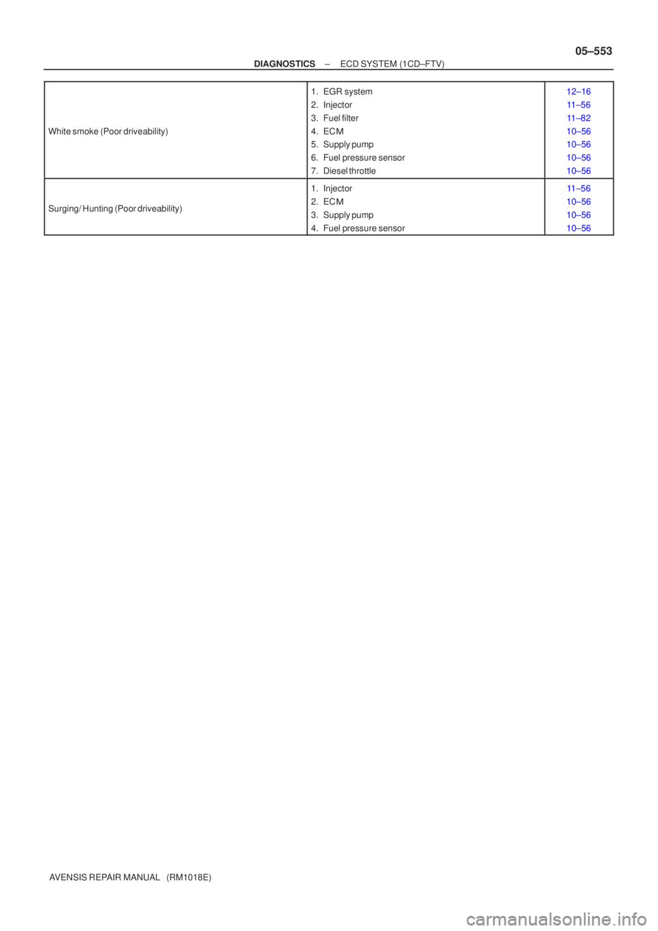
White smoke (Poor driveability)
1. EGR system
2. Injector
3. Fuel filter
4. EC
�
5. Supply pump
6. Fuel pressure sensor
7. Diesel throttle12±16
11±56
11±82
10±56
10±56
10±56
10±56
Surging/ Hunting (Poor driveability)
1. Injector
2. EC �
3. Supply pump
4. Fuel pressure sensor11±56
10±56
10±56
10±56
(A) (A)
E11
OC1 +OC1±
±
DIAGNOSTICS SFI SYSTEM(1AZ±FSE)
05±327
AVENSIS REPAIR MANUAL (RM1018E)
4INSPECT ECM(OCV SIGNAL)
(a)Inspect")

AVENSIS REPAIR MANUAL (RM1018E)
9REPLACE CAMSHAFT TIMING GEAR ASSY (See page 14±240)
GO
10CHECK BLOCKAGE(OCV, OIL CHECK VALVE AND OIL HOLE)
NGREPAIR OR R")