Page 643 of 5135
A66074
A66289
Inside
05±542
±
DIAGNOSTICS ECD SYSTEM(1CD±FTV)
AVENSIS REPAIR MANUAL (RM1018E)
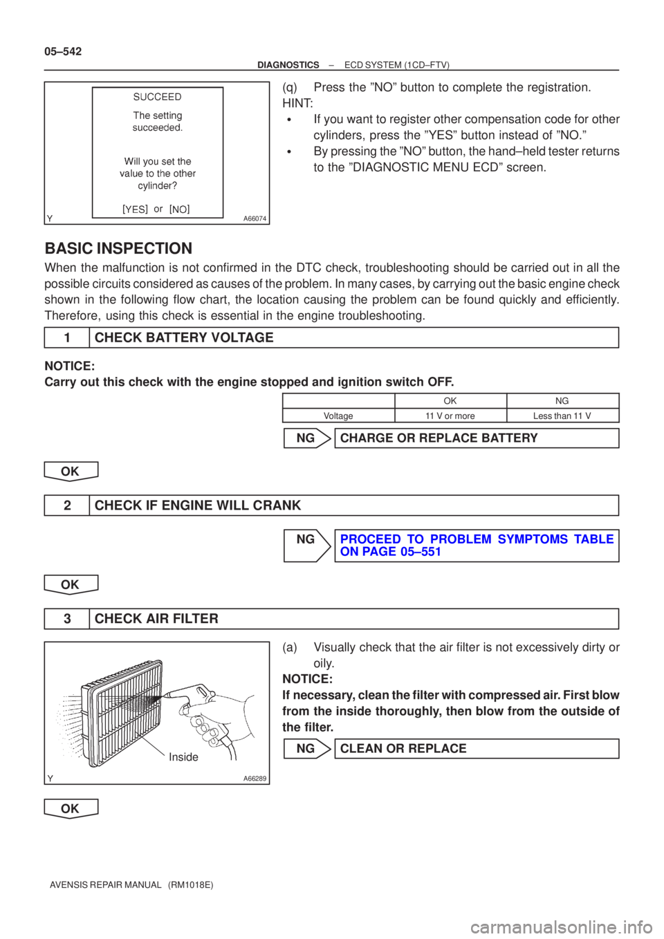
(q)Press the ºNOº button to complete the registration.
HINT:
�If you want to register other compensation code for other
cylinders, press the ºYESº button instead of ºNO.º
�By pressing the ºNOº button, the hand±held tester returns
to the ºDIAGNOSTIC MENU ECDº screen.
BASIC INSPECTION
When the malfunction is not confirmed in the DTC check, troubleshooting shou\
ld be carried out in all the
possible circuits considered as causes of the problem. In many cases, by carrying out the basic engine check
shown in the following flow chart, the location causing the problem can be found quickly and efficiently.
Therefore, using this check is essential in the engine troubleshooting.
1CHECK BATTERY VOLTAGE
NOTICE:
Carry out this check with the engine stopped and ignition switch OFF.
OKNG
Voltage11 V or moreLess than 11 V
NGCHARGE OR REPLACE BATTERY
OK
2CHECK IF ENGINE WILL CRANK
NGPROCEED TO PROBLEM SYMPTOMS TABLE ON PAGE 05±551
OK
3 CHECK AIR FILTER
(a) Visually check that the air filter is not excessively dirty or oily.
NOTICE:
If necessary, clean the filter with compressed air. First blow
from the inside thoroughly, then blow from the outside of
the filter.
NG CLEAN OR REPLACE
OK
Page 650 of 5135
05CP9±01
A81021
Common Rail System Diagram (1CD±FTV Fuel System)
Sensors
ECM
EDU
Common Rail
Fuel Pressure SensorPressure Discharge
Valve
Supply Pump Assy
Suction Control ValveFuel TankInjector
Fuel Filter
: High±pressure Area
± DIAGNOSTICSECD SYSTEM (1CD±FTV)
05±517
AVENSIS REPAIR MANUAL (RM1018E)
ECD SYSTEM (1CD±FTV)
DESCRIPTION
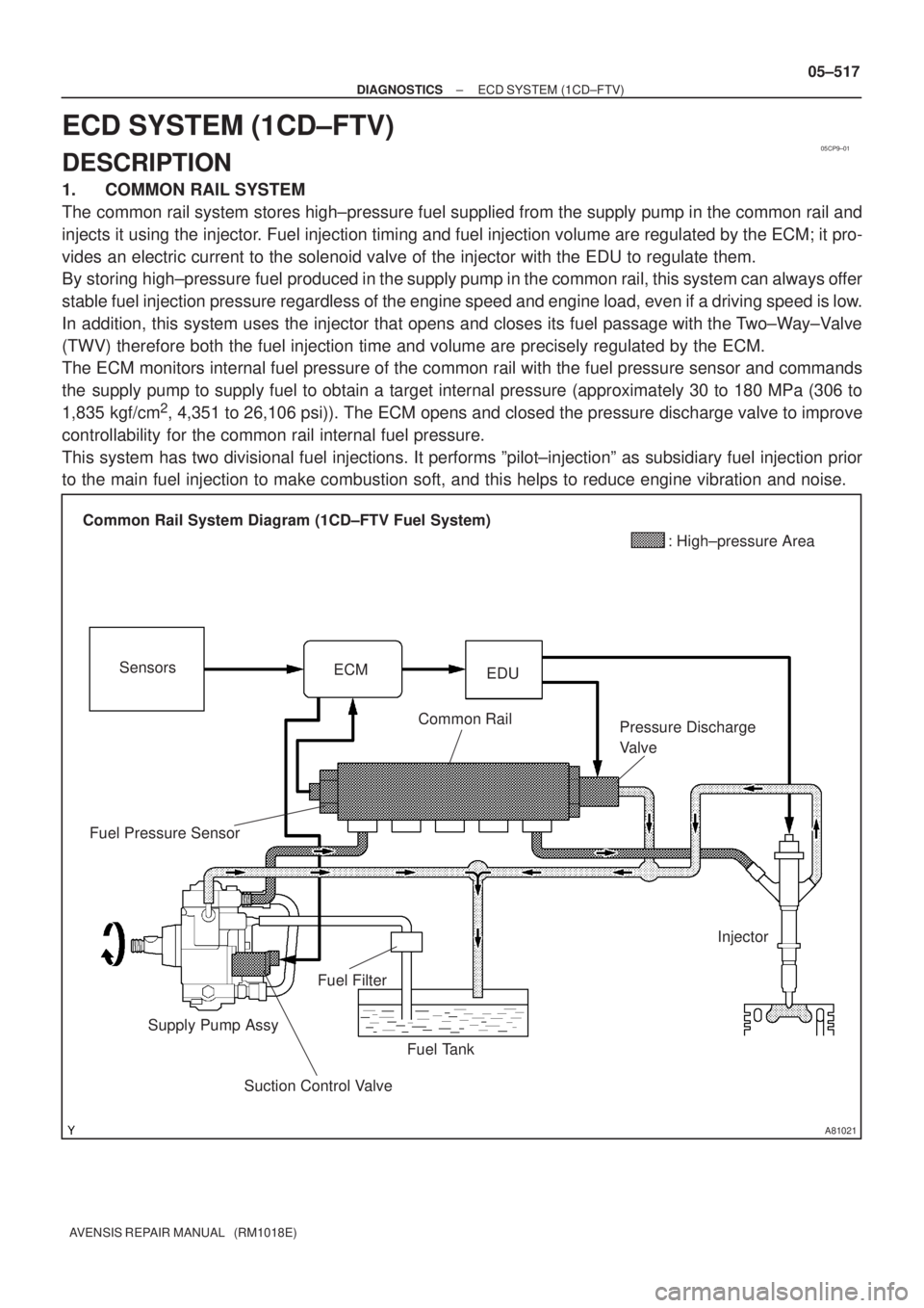
1. COMMON RAIL SYSTEM
The common rail system stores high±pressure fuel supplied from the supply pump in the common rail and
injects it using the injector. Fuel injection timing and fuel injection volume are regulated by the ECM; it pro-
vides an electric current to the solenoid valve of the injector with the EDU to regulate them.
By storing high±pressure fuel produced in the supply pump in the common rail, this system can always offer
stable fuel injection pressure regardless of the engine speed and engine load, even if a driving speed is low.
In addition, this system uses the injector that opens and closes its fuel passage with the Two±Way±Valve
(TWV) therefore both the fuel injection time and volume are precisely regulated by the ECM.
The ECM monitors internal fuel pressure of the common rail with the fuel pressure sensor and commands
the supply pump to supply fuel to obtain a target internal pressure (approximately 30 to 180 MPa (306 to
1,835 kgf/cm
2, 4,351 to 26,106 psi)). The ECM opens and closed the pressure discharge valve to improve
controllability for the common rail internal fuel pressure.
This system has two divisional fuel injections. It performs ºpilot±injectionº as subsidiary fuel injection prior
to the main fuel injection to make combustion soft, and this helps to reduce engine vibration and noise.
Page 725 of 5135

A66060
E13
ECM ConnectorE12
VN
E1
A05967
E±VRV Signal Waveforms
GND
5V/
Division
1 msec./ Division
A15518Air
Air Filter
E
E
Air
F VRV: ON
VRV: OFF
05±614
±
DIAGNOSTICS ECD SYSTEM(1CD±FTV)
AVENSIS REPAIR MANUAL (RM1018E)
4INSPECT ECM(VN VOLTAGE)
(a)Inspect using the oscilloscope.
(b)During idling, check the waveform between the specified terminals of the E12 and E13 ECM connectors.
Standard:
Symbols (Terminal No.)Specified condition
VN (E13±10) ± E1 (E12±7)Correct waveform is as shown
NGREPLACE ECM (See page 10±65)
OK
5INSPECT VACUUM REGULATING VALVE ASSY(OPERATION)
(a)Disconnect the vacuum hoses from the VRV.
(b)Turn the ignition switch ON.
(c)Check for operation of the E±VRV when it is operated by the hand±held tester.
VRV ON:
Air from port E flows out through port F.
VRV OFF:
Air from port E flows out through air filter.
NGREPLACE VACUUM REGULATING VALVE ASSY
OK
6INSPECT VACUUM REGULATING VALVE ASSY(RESISTANCE) (See page 12±16)
NG REPLACE VACUUM REGULATING VALVE ASSY
OK
Page 850 of 5135
������F45775
Engine Room J/B No.4
ALT 1
4B1
4D B±G (*1)
B±L (*2) FL MAINS2 20
IR1Skid Control ECU
with Actuator
DA
DA DNDMDL 1
1 2
1
1 22
22 STOPDriver Side J/B
G±W (*4) G±W (*4)
G±W (*3)
G±W (*3)6
IE3
IE3 IR12
11
R±W (*3) R±W (*4) R±W (*4)
R±W (*3) S13
Stop Light SW
G±W
G±W
B±G (*1)
STP
123 ALT Engine Room R/B No.3
W (*2)
ED11 12
J/C
J30B
(*5) (*6) (*7) (*5) (*6) (*7)
(*5) (*6) (*7) (*5) (*6) (*7)STOP
STOP J31CJ32
J/C
B (*2)
W±B (*5) G±W (*5) W±B (*5)
W±B
W±B
W±B
(*5)
CC2 1
R13
R14 R14 R14 R14 R14 R14R13 R13 R13 R13 R13J30
J30
J30 J31
J31 21
1 54 64
4 7 3
3 3 6
G±WJ/C
C
C
C B B
G±W G±W
G±W (*6, *7)
BG1Rear Combination Light LHH20
High Mounted Stop Light
N8
Noise
Filter
(Stop Light) Rear Combination Light RH
H20 High Mounted
Stop Light
W±B (*7)
W±B (*7)G±W (*7)
W±B (*7) W±B (*7) W±B (*6)W±B (*6)G±W (*6)
W±B (*6, *7)
W±B (*6, *7)
W±B
(*6) (*7)W±B (*6)
W±B (*6)
J33 J34AAJ/C1 2BE1
BD1 BF113
G±W L(*6)
L(*7)
BD1 BF1(*6) (*7)(*6, *7)
G±W
(*6, *7)
1
BX BE1 BG1 41
2 3
24
BT BS Battery
*1: Gasoline
*2: 1CD±FTV
*3: LHD
*4: RHD*5: S/D
*6: L/B
*7: W/G
± DIAGNOSTICSABS WITH EBD SYSTEM
05±731
AVENSIS REPAIR MANUAL (RM1018E)
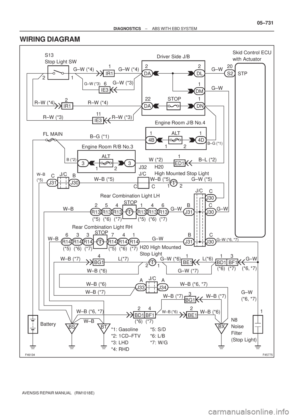
WIRING DIAGRAM
Page 896 of 5135

������F45775
Engine Room J/B No.4
ALT 1
4B1
4D B±G (*1)
B±L (*2) FL MAINS1 37
IR1Skid Control ECU
with Actuator
DA
DA DNDMDL 1
1 2
1
1 22
22 STOPDriver Side J/B
G±W (*4) G±W (*4)
G±W (*3)
G±W (*3)6
IE3
IE3 IR12
11
R±W (*3) R±W (*4) R±W (*4)
R±W (*3) S13
Stop Light SW
G±W
G±W
B±G (*1)
STP
123 ALT Engine Room R/B No.3
W (*2)
ED11 12
J/C
J30B
(*5) (*6) (*7) (*5) (*6) (*7)
(*5) (*6) (*7) (*5) (*6) (*7)STOP
STOP J31CJ32
J/C
B (*2)
W±B (*5) G±W (*5) W±B (*5)
W±B
W±B
W±B
(*5)
CC2 1
R13
R14 R14 R14 R14 R14 R14R13 R13 R13 R13 R13J30
J30
J30 J31
J31 21
1 54 64
4 7 3
3 3 6
G±WJ/C
C
C
C B B
G±W G±W
G±W (*6, *7)
BG1Rear Combination Light LHH20
High Mounted Stop Light
N8
Noise
Filter
(Stop Light) Rear Combination Light RH
H20 High Mounted
Stop Light
W±B (*7)
W±B (*7)G±W (*7)
W±B (*7) W±B (*7) W±B (*6)W±B (*6)G±W (*6)
W±B (*6, *7)
W±B (*6, *7)
W±B
(*6) (*7)W±B (*6)
W±B (*6)
J33 J34AAJ/C1 2BE1
BD1 BF113
G±W L(*6)
L(*7)
BD1 BF1(*6) (*7)(*6, *7)
G±W
(*8, *9)
1
BX BE1 BG1 41
2 3
24
BT BS Battery
*1: 1AZ±FSE
*2: 1CD±FTV
*3: LHD
*4: RHD*5: S/D
*6: L/B
*7: W/G 05±816
± DIAGNOSTICSABS WITH EBD & BA & TRC & VSC SYSTEM
AVENSIS REPAIR MANUAL (RM1018E)
WIRING DIAGRAM
Page 965 of 5135

A79094
*1: LHD
*2: RHD
*3: SEDAN
*4: LIFT BACK
*5: WAGON IE36
IR11 G±W
(*1)
G±W
(*2)G±W
G±W(*1)
(*2)
1
2DA DC
DM
1 210Driver Side J/B
E10STPECM
19
G±W
G±W
G±WG±W
G±W
G±W
G±W
G±W J30 C
BJ30 J30
J31
J31
B CC
2
1 R±W
IR1 2 IE3 11
DA22
STOP
DN1Driver
Side J/BCH20
High Mounted
Stop Light
J32
Junction
Connector W±B (*1)(*2) R±W
R±W
(*1)(*2) R±W(*3)
(*3)
C(*4, *5)
(*4, *5)
(*4, *5)
(*4)
(*5)
6 4 1
4 5 21 4 7
3 3 6 (*3)
(*4)
(*5)(*3)
(*4)
(*5)
(*3)
(*4)
(*5)(*3)
(*4)
(*5) R13
Rear
Combination
Light LHR14
Rear
Combination
Light RH Junction
ConnectorN8
Noise
FilterBD1 1
BF1 3
BE1 1L
G±W
G±W
1
2 H20
High
Mounted
Stop Light(*4)
(*4)(*5)
L
W±B
W±B (*4)(*5)
(*5)
(*4) (*4)
(*5)
(*4) (*5)
(*5)(*4, *5) W±B W±B
W±B
W±BW±B W±B
(*3)
W±B
(*3)W±B W±B
W±B
(*4, *5)
W±B Junction
Connector
Junction
Connector Engine
Room
J/B No.4 B±G
B±GALT 2
1
4B 14D
FL MAIN 1
J31 J30 B
CBD1
BF1BG1
J33
J34 BE1
BG14
A
A 2
2
3 4
Battery
BS
BTBX S13
Stop Light
Switch1 05±906
± DIAGNOSTICSELECTRONIC CONTROLLED AUTOMATIC
TRANSAXLE [ECT] (U241E(1AZ±FE))
AVENSIS REPAIR MANUAL (RM1018E)
WIRING DIAGRAM
Page 1425 of 5135
05±1404
± DIAGNOSTICSAUDIO SYSTEM
AVENSIS REPAIR MANUAL (RM1018E)
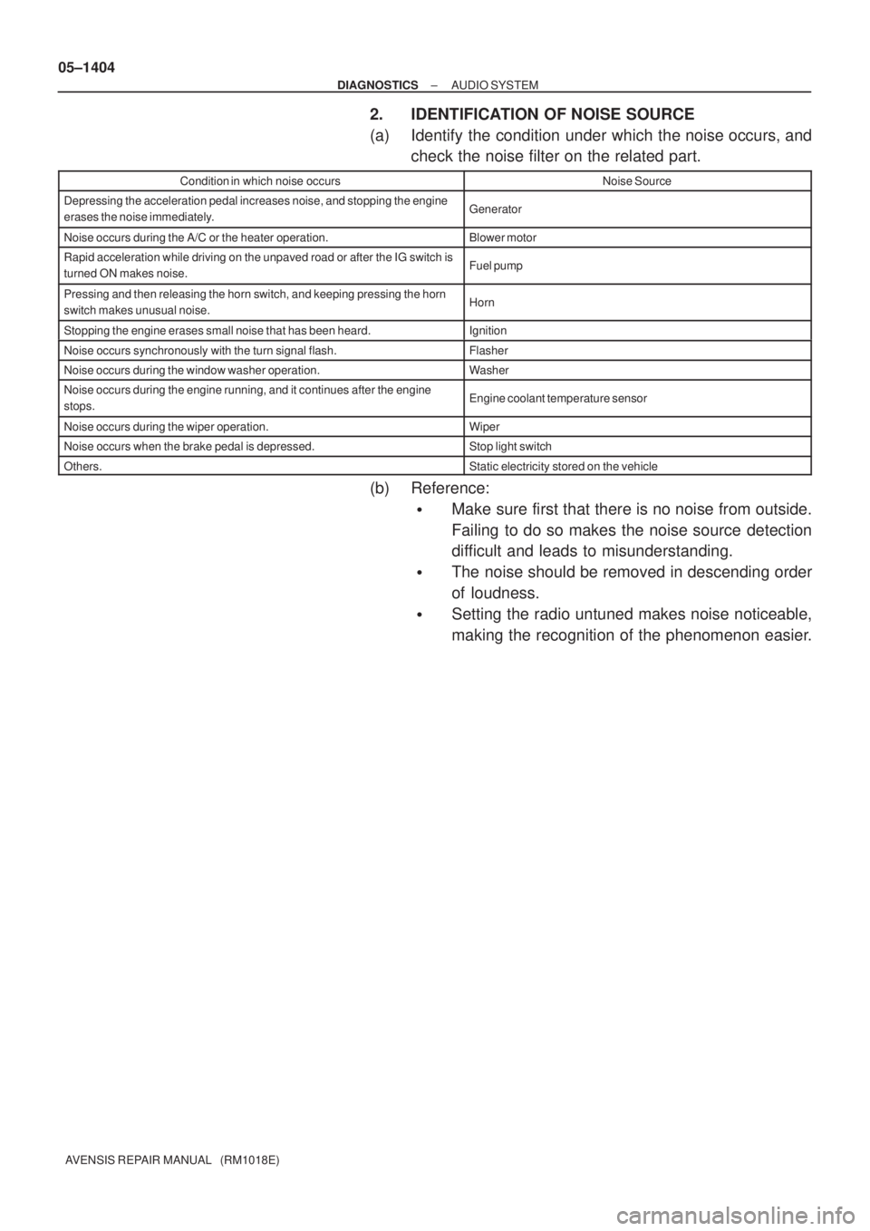
2. IDENTIFICATION OF NOISE SOURCE
(a) Identify the condition under which the noise occurs, and
check the noise filter on the related part.
Condition in which noise occursNoise Source
Depressing the acceleration pedal increases noise, and stopping the engine
erases the noise immediately.Generator
Noise occurs during the A/C or the heater operation.Blower motor
Rapid acceleration while driving on the unpaved road or after the IG switch is
turned ON makes noise.Fuel pump
Pressing and then releasing the horn switch, and keeping pressing the horn
switch makes unusual noise.Horn
Stopping the engine erases small noise that has been heard.Ignition
Noise occurs synchronously with the turn signal flash.Flasher
Noise occurs during the window washer operation.Washer
Noise occurs during the engine running, and it continues after the engine
stops.Engine coolant temperature sensor
Noise occurs during the wiper operation.Wiper
Noise occurs when the brake pedal is depressed.Stop light switch
Others.Static electricity stored on the vehicle
(b) Reference:
�Make sure first that there is no noise from outside.
Failing to do so makes the noise source detection
difficult and leads to misunderstanding.
�The noise should be removed in descending order
of loudness.
�Setting the radio untuned makes noise noticeable,
making the recognition of the phenomenon easier.
Page 1475 of 5135
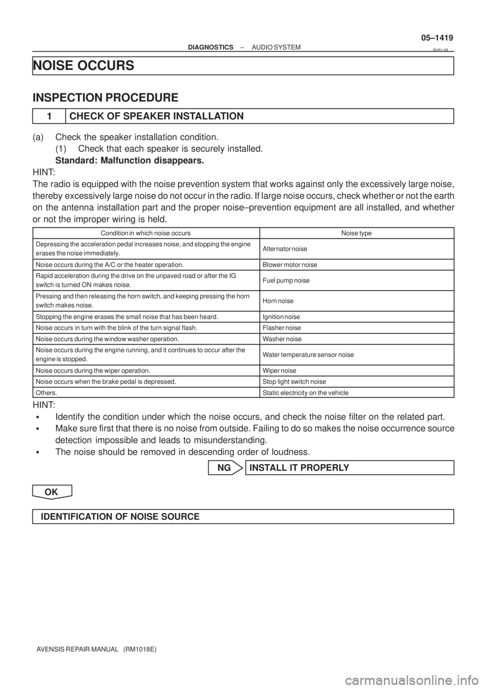
± DIAGNOSTICSAUDIO SYSTEM
05±1419
AVENSIS REPAIR MANUAL (RM1018E)
NOISE OCCURS
INSPECTION PROCEDURE
1 CHECK OF SPEAKER INSTALLATION
(a) Check the speaker installation condition.
(1) Check that each speaker is securely installed.
Standard: Malfunction disappears.
HINT:
The radio is equipped with the noise prevention system that works against only the excessively large noise,
thereby excessively large noise do not occur in the radio. If large noise occurs, check whether or not the earth
on the antenna installation part and the proper noise±prevention equipment are all installed, and whether
or not the improper wiring is held.
Condition in which noise occursNoise type
Depressing the acceleration pedal increases noise, and stopping the engine
erases the noise immediately.Alternator noise
Noise occurs during the A/C or the heater operation.Blower motor noise
Rapid acceleration during the drive on the unpaved road or after the IG
switch is turned ON makes noise.Fuel pump noise
Pressing and then releasing the horn switch, and keeping pressing the horn
switch makes noise.Horn noise
Stopping the engine erases the small noise that has been heard.Ignition noise
Noise occurs in turn with the blink of the turn signal flash.Flasher noise
Noise occurs during the window washer operation.Washer noise
Noise occurs during the engine running, and it continues to occur after the
engine is stopped.Water temperature sensor noise
Noise occurs during the wiper operation.Wiper noise
Noise occurs when the brake pedal is depressed.Stop light switch noise
Others.Static electricity on the vehicle
HINT:
�Identify the condition under which the noise occurs, and check the noise filter on the related part.
�Make sure first that there is no noise from outside. Failing to do so makes the noise occurrence source
detection impossible and leads to misunderstanding.
�The noise should be removed in descending order of loudness.
NG INSTALL IT PROPERLY
OK
IDENTIFICATION OF NOISE SOURCE
054A1±09