Page 207 of 5135

±
DIAGNOSTICS SFI SYSTEM(1ZZ±FE/3ZZ±FE)
05±79
AVENSIS REPAIR MANUAL (RM1018E)
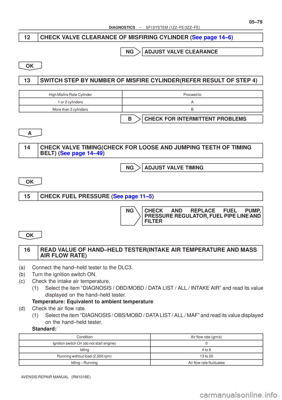
12CHECK VALVE CLEARANCE OF MISFIRING CYLINDER (See page 14±6)
NGADJUST VALVE CLEARANCE
OK
13SWITCH STEP BY NUMBER OF MISFIRE CYLINDER(REFER RESULT OF STEP 4)
High Misfire Rate CylinderProceed to
1 or 2 cylindersA
More than 3 cylindersB
BCHECK FOR INTERMITTENT PROBLEMS
A
14CHECK VALVE TIMING(CHECK FOR LOOSE AND JUMPING TEETH OF TIMING BELT) (See page 14±49)
NGADJUST VALVE TIMING
OK
15CHECK FUEL PRESSURE (See page 11±5)
NG CHECK AND REPLACE FUEL PUMP, PRESSURE REGULATOR, FUEL PIPE LINE AND
FILTER
OK
16 READ VALUE OF HAND±HELD TESTER(INTAKE AIR TEMPERATURE AND MASS AIR FLOW RATE)
(a) Connect the hand±held tester to the DLC3.
(b) Turn the ignition switch ON.
(c) Check the intake air temperature.
(1) Select the item ºDIAGNOSIS / OBD/MOBD / DATA LIST / ALL / INTAKE AIRº and read its valuedisplayed on the hand±held tester.
Temperature: Equivalent to ambient temperature
(d) Check the air flow rate. (1) Select the item ºDIAGNOSIS / OBS/MOBD / DATA LIST / ALL / MAFº and read its value displayedon the hand±held tester.
Standard:
ConditionAir flow rate (gm/s)
Ignition switch On (do not start engine)0
Idling4 to 6
Running without load (2,500 rpm)13 to 20
Idling ± RunningAir flow rate fluctuates
Page 255 of 5135

A79094
*1: LHD
*2: RHD
*3: SEDAN
*4: LIFT BACK
*5: WAGON IE36
IR11 G±W
(*1)
G±W
(*2)G±W
G±W(*1)
(*2)
1
2DA DC
DM
1 210Driver Side J/B
E10STPECM
19
G±W
G±W
G±WG±W
G±W
G±W
G±W
G±W J30 C
BJ30 J30
J31
J31
B CC
2
1 R±W
IR1 2 IE3 11
DA22
STOP
DN1Driver
Side J/BCH20
High Mounted
Stop Light
J32
Junction
Connector W±B (*1)(*2) R±W
R±W
(*1)(*2) R±W(*3)
(*3)
C(*4, *5)
(*4, *5)
(*4, *5)
(*4)
(*5)
6 4 1
6 5 21 4 7
3 3 6 (*3)
(*4)
(*5)(*3)
(*4)
(*5)
(*3)
(*4)
(*5)(*3)
(*4)
(*5) R13
Rear
Combination
Light LHR14
Rear
Combination
Light RH Junction
ConnectorN8
Noise
FilterBD1 1
BF1 3
BE1 1L
G±W
G±W
1
2 H20
High
Mounted
Stop Light(*4)
(*4)(*5)
L
W±B
W±B (*4)(*5)
(*5)
(*4) (*4)
(*5)
(*4) (*5)
(*5)(*4, *5) W±B W±B
W±B
W±BW±B W±B
(*3)
W±B
(*3)W±B W±B
W±B
(*4, *5)
W±B Junction
Connector
Junction
Connector Engine
Room
J/B No.4 B±G
B±GALT 2
1
4B 14D
FL MAIN 1
J31 J30 B
CBD1
BF1BG1
J33
J34 BE1
BG14
A
A 2
2
3 4
Battery
BS
BTBX S13
Stop Light
Switch1 05±116
± DIAGNOSTICSSFI SYSTEM (1ZZ±FE/3ZZ±FE)
AVENSIS REPAIR MANUAL (RM1018E)
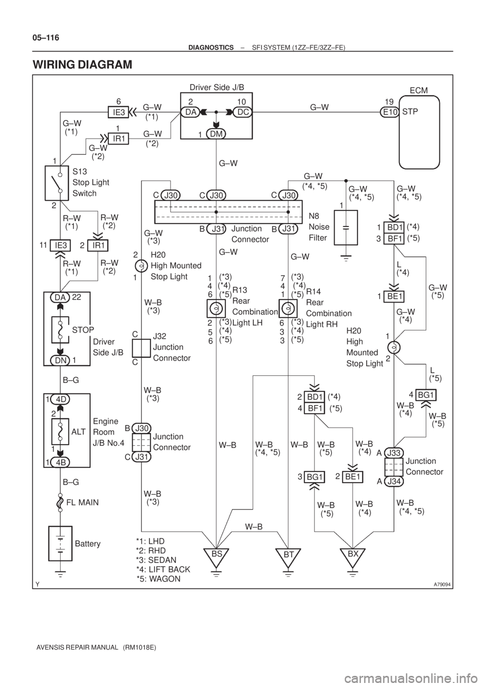
WIRING DIAGRAM
Page 259 of 5135

A18294
OCV+OCV±
ECM Connector
E13
A58701A58701
OCV Signal Waveform1 m sec./Division 5 V/
Division
GND
(A)(A)(A)
±
DIAGNOSTICS SFI SYSTEM(1ZZ±FE/3ZZ±FE)
05±113
AVENSIS REPAIR MANUAL (RM1018E)
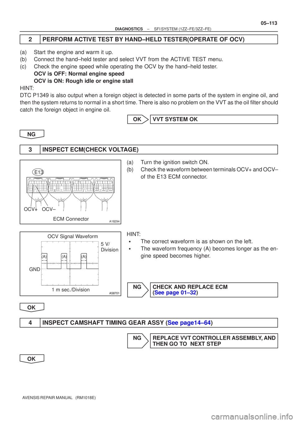
2PERFORM ACTIVE TEST BY HAND±HELD TESTER(OPERATE OF OCV)
(a)Start the engine and warm it up.
(b)Connect the hand±held tester and select VVT from the ACTIVE TEST menu\
.
(c)Check the engine speed while operating the OCV by the hand±held teste\
r.
OCV is OFF: Normal engine speed
OCV is ON: Rough idle or engine stall
HINT:
DTC P1349 is also output when a foreign object is detected in some parts\
of the system in engine oil, and
then the system returns to normal in a short time. There is also no problem \
on the VVT as the oil filter should
catch the foreign object in engine oil.
OKVVT SYSTEM OK
NG
3INSPECT ECM(CHECK VOLTAGE)
(a)Turn the ignition switch ON.
(b)Check the waveform between terminals OCV+ and OCV± of the E13 ECM connector.
HINT:
�The correct waveform is as shown on the left.
�The waveform frequency (A) becomes longer as the en-
gine speed becomes higher.
NGCHECK AND REPLACE ECM (See page 01±32)
OK
4INSPECT CAMSHAFT TIMING GEAR ASSY (See page14±64)
NG REPLACE VVT CONTROLLER ASSEMBLY, AND THEN GO TO NEXT STEP
OK
Page 260 of 5135
05±114
±
DIAGNOSTICS SFI SYSTEM(1ZZ±FE/3ZZ±FE)
AVENSIS REPAIR MANUAL (RM1018E)
5INSPECT CAMSHAFT TIMING OIL CONTROL VALVE ASSY (See page 10±3)
NGREPLACE CAMSHAFT TIMING OIL CONTROL VALVE ASSEMBLY, AND THEN GO TO NEXT
STEP
OK
6CHECK OIL CONTROL VALVE FILTER(CHECK BLOCKAGE)
NGREPAIR OR REPLACE OIL CONTROL VALVE FILTER
OK
7PERFORM SIMULATION TEST(DTC CHECK)
(a)Clear the DTC (See page 05±5).
(b)Perform the simulation test.
(c)Check whether or not DTC P1349 is stored (See page 05±5). Result:
DTCProceed to
ºP1349º is output.A
ºP1349º is not output.B
HINT:
DTC P1349 is also output when a foreign object is detected in some parts\
of the system in engine oil, and
then the system returns to normal in a short time. There is also no problem \
on the VVT as the oil filter should
catch the foreign object in the engine oil.
BVVT SYSTEM OK
A
CHECK AND REPLACE ECM (See page 01±32)
Page 263 of 5135
������A79093
ECM
EH W±B E13
IGT1
IGF
E13
E13
E13
E13 23 IGT2
IGT3
IGT4
8
10
11
R±W
3
2
1
I1
Ignition Coil and
Igniter No.1
I2
Ignition Coil and
Igniter No.2
I3
Ignition Coil and
Igniter No.3
I4
Ignition Coil and
Igniter No.4
R±B
W±B 4 3
2
B±R
1
1
1
B±R
R±B
33
2
2
L±YW±R
W±R W±R
4 4 4
W±B
W±B
W±B
W±B
R±B
W±R
R±B R±B
From Terminal 3
of IG2 Relay
(See Page 05±124)
W±B LG±B
P
W±R
W±R
W±R 9
R±B 1N2
Noise
Filter R±B
8 EA1
±
DIAGNOSTICS SFI SYSTEM (1ZZ±FE/3ZZ±FE)
05±105
AVENSIS REPAIR MANUAL (RM1018E)
WIRING DIAGRAM
Page 404 of 5135
A76873
8
IGF IGT2 IGT1
IGT3 E13
IGT4 I1
Ignition Coil and
Igniter No. 1
P R±W
IGNW±R IE4
LG±B
ECR±B
L±YE13
E13
E13
E139
1110
13 I2
Ignition Coil and
Igniter No. 2
I3
Ignition Coil and
Igniter No. 3
I4
Ignition Coil and
Igniter No. 4W±R
W±RW±R 3
2
14
1
42
2 3
3
3 1
4
4 1 R±B R±B
R±B R±B R±B B±R
W±B
W±B
W±B
W±BW±B W±BW±B
1
N2
Noise Filter
(Ignition)R±B B±R 1
3 Engine Room R/B No. 1 and
Engine Room J/B No.1
B±G 1A
2
B±G
FL MAIN
Battery Engine Room
J/B No.4I13
Ignition Switch
6
AM2 IG24
(LHD)IP11
(RHD)
B±R
1
1
1 1 2
2 AM2IG2
1B±R
BB
5144
44DH 2
DL 16
IG2
Relay
4A 1
4B 1Engine
Room
R/B No.4
EA1
8R±B
R±BW±B
EF B±R2ECM
W±R
W±R Driver
Side J/B 05±234
± DIAGNOSTICSSFI SYSTEM (1AZ±FE)
AVENSIS REPAIR MANUAL (RM1018E)
WIRING DIAGRAM
Page 439 of 5135

A59673
Inside
±
DIAGNOSTICS SFI SYSTEM(1AZ±FSE)
05±307
AVENSIS REPAIR MANUAL (RM1018E)
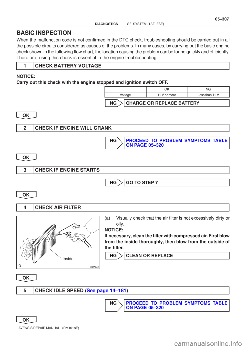
BASIC INSPECTION
When the malfunction code is not confirmed in the DTC check, troubleshooting should be carried out in all
the possible circuits considered as causes of the problems. In many cases, by carrying out the basic engi\
ne
check shown in the following flow chart, the location causing the problem can be found quickly and efficiently.
Therefore, using this check is essential in the engine troubleshooting.
1CHECK BATTERY VOLTAGE
NOTICE:
Carry out this check with the engine stopped and ignition switch OFF.
OKNG
Voltage11 V or moreLess than 11 V
NGCHARGE OR REPLACE BATTERY
OK
2CHECK IF ENGINE WILL CRANK
NGPROCEED TO PROBLEM SYMPTOMS TABLE ON PAGE 05±320
OK
3CHECK IF ENGINE STARTS
NGGO TO STEP 7
OK
4CHECK AIR FILTER
(a)Visually check that the air filter is not excessively dirty or oily.
NOTICE:
If necessary, clean the filter with compressed air. First blow
from the inside thoroughly, then blow from the outside of
the filter.
NGCLEAN OR REPLACE
OK
5CHECK IDLE SPEED (See page 14±181)
NGPROCEED TO PROBLEM SYMPTOMS TABLE ON PAGE 05±320
OK
Page 498 of 5135

05±326
± DIAGNOSTICSSFI SYSTEM (1AZ±FSE)
AVENSIS REPAIR MANUAL (RM1018E)
2 PERFORM ACTIVE TEST BY HAND±HELD TESTER(OPERATE OCV)
(a) Connect the hand±held tester to the DLC3.
(b) Start the engine and warm it up.
(c) Turn the ignition switch ON and push the hand±held tester main switch ON.
(d) Select the item ºDIAGNOSIS / OBD/MOBD / ACTIVE TEST / VVT CTRL B1º.
(e) Check the engine speed when operating the OCV by the hand±held tester.
Standard:
Tester operationSpecified condition
OCV is OFFNormal engine speed
OCV is ONRough idle or engine stall
NG Go to step 4
OK
3 CHECK IF DTC OUTPUTS REOCCUR
(a) Clear the DTC.
(1) Operating the hand±held tester to erase the codes, or disconnecting the battery terminal or the
EFI and ETCS fuses for 60 seconds or more.
(b) Start the engine and warm it up.
(c) Drive the vehicle around for 10 minutes or more.
(d) Read output DTC using the hand±held tester.
Standard: No DTC output.
HINT:
*: DTCs P0011 or P0012 is output when a foreign object in engine oil is caught in some part of the system.
These codes will stay registered even if the system returns to normal after a short time. These foreign objects
are then captured by the oil filter, thus eliminating the source of the problem.
OK VVT SYSTEM OK *
NG