Page 2476 of 5135

190NK±01
A78515
A78516
A77903
(a)
(a)
(b)
(b)
(b)
A77904
(f)
(f)
(e)
(d)
Terminal Cap
19±20
±
STARTING & CHARGING GENERATOR ASSY(1AZ±FE/1AZ±FSE)
AVENSIS REPAIR MANUAL (RM1018E)
GENERATOR ASSY(1AZ±FE/1AZ±FSE)
REPLACEMENT
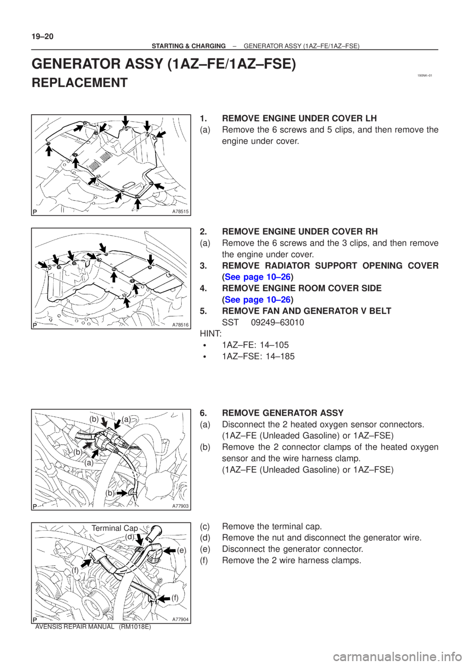
1.REMOVE ENGINE UNDER COVER LH
(a)Remove the 6 screws and 5 clips, and then remove the engine under cover.
2.REMOVE ENGINE UNDER COVER RH
(a)Remove the 6 screws and the 3 clips, and then remove the engine under cover.
3.REMOVE RADIATOR SUPPORT OPENING COVER (See page 10±26)
4. REMOVE ENGINE ROOM COVER SIDE (See page 10±26)
5. REMOVE FAN AND GENERATOR V BELT SST 09249±63010
HINT:
�1AZ±FE: 14±105
�1AZ±FSE: 14±185
6. REMOVE GENERATOR ASSY
(a) Disconnect the 2 heated oxygen sensor connectors. (1AZ±FE (Unleaded Gasoline) or 1AZ±FSE)
(b) Remove the 2 connector clamps of the heated oxygen sensor and the wire harness clamp.
(1AZ±FE (Unleaded Gasoline) or 1AZ±FSE)
(c) Remove the terminal cap.
(d) Remove the nut and disconnect the generator wire.
(e) Disconnect the generator connector.
(f) Remove the 2 wire harness clamps.
Page 2477 of 5135

A77905
A77906
A77905
A
B
± STARTING & CHARGINGGENERATOR ASSY (1AZ±FE/1AZ±FSE)
19±21
AVENSIS REPAIR MANUAL (RM1018E)
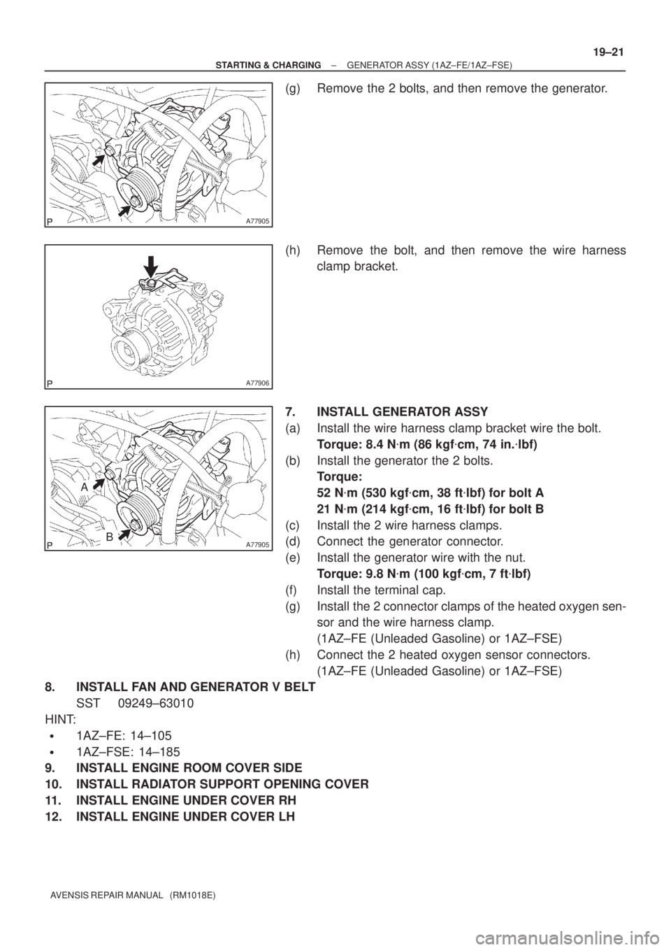
(g) Remove the 2 bolts, and then remove the generator.
(h) Remove the bolt, and then remove the wire harness
clamp bracket.
7. INSTALL GENERATOR ASSY
(a) Install the wire harness clamp bracket wire the bolt.
Torque: 8.4 N�m (86 kgf�cm, 74 in.�lbf)
(b) Install the generator the 2 bolts.
Torque:
52 N�m (530 kgf�cm, 38 ft�lbf) for bolt A
21 N�m (214 kgf�cm, 16 ft�lbf) for bolt B
(c) Install the 2 wire harness clamps.
(d) Connect the generator connector.
(e) Install the generator wire with the nut.
Torque: 9.8 N�m (100 kgf�cm, 7 ft�lbf)
(f) Install the terminal cap.
(g) Install the 2 connector clamps of the heated oxygen sen-
sor and the wire harness clamp.
(1AZ±FE (Unleaded Gasoline) or 1AZ±FSE)
(h) Connect the 2 heated oxygen sensor connectors.
(1AZ±FE (Unleaded Gasoline) or 1AZ±FSE)
8. INSTALL FAN AND GENERATOR V BELT
SST 09249±63010
HINT:
�1AZ±FE: 14±105
�1AZ±FSE: 14±185
9. INSTALL ENGINE ROOM COVER SIDE
10. INSTALL RADIATOR SUPPORT OPENING COVER
11. INSTALL ENGINE UNDER COVER RH
12. INSTALL ENGINE UNDER COVER LH
Page 2484 of 5135
190NJ±01
A77898
A77899
(a)
(a)
(a)(c)
(d)
Terminal Cap Cover
A77900
A77901
19±12
±
STARTING & CHARGING STARTER ASSY(1AZ±FE/1AZ±FSE)
AVENSIS REPAIR MANUAL (RM1018E)
STARTER ASSY(1AZ±FE/1AZ±FSE)
REPLACEMENT
1.REMOVE RADIATOR SUPPORT OPENING COVER (See page 10±26)
2. REMOVE BATTERY CLAMP SUB±ASSY
3. REMOVE BATTERY
4. REMOVE BATTERY TRAY 5. REMOVE BATTERY CARRIER
(a) Remove the 4 bolts, and then remove the battery carrier.
6. REMOVE STARTER ASSY
(a) Remove the 3 wire harness clamps.
(b) Open the terminal cap cover.
(c) Remove the nut and disconnect the starter wire.
(d) Disconnect the starter connector.
(e) Remove the 2 bolts, and then remove the starter.
(f) Remove the bolt, and then remove the wire harnessclamp bracket.
Page 2485 of 5135
± STARTING & CHARGINGSTARTER ASSY (1AZ±FE/1AZ±FSE)
19±13
AVENSIS REPAIR MANUAL (RM1018E)
7. INSTALL STARTER ASSY
(a) Install the wire harness clamp bracket with the bolt.
Torque: 8.4 N�m (86 kgf�cm, 74 in.�lbf)
(b) Install the starter with the 2 bolts.
Torque: 37 N�m (380 kgf�cm, 28 ft�lbf)
(c) Connect the starter connector.
(d) Connect the starter wire with the nut.
Torque: 9.8 N�m (100 kgf�cm, 7 ft�lbf)
(e) Close the terminal cap cover.
(f) Install the 3 wire harness clamps.
8. INSTALL BATTERY CARRIER
Torque: 13 N�m (131 kgf�cm, 9 ft�lbf)
9. INSTALL BATTERY TRAY
10. INSTALL BATTERY
11. INSTALL BATTERY CLAMP SUB±ASSY
Torque:
5.0 N�m (51 kgf�cm, 44 in.�lbf) for bolt
3.6 N�m (36 kgf�cm, 31 in.�lbf) for nut
5.4 N�m (55 kgf�cm, 48 in.�lbf) for terminal
12. INSTALL RADIATOR SUPPORT OPENING COVER
Page 2693 of 5135
40121±02
D30480
C81535
D30341
± AUTOMATIC TRANSMISSION / TRANSAUTOMATIC TRANSAXLE ASSY (U241E)
40±25
AVENSIS REPAIR MANUAL (RM1018E)
REPLACEMENT
1. REMOVE HOOD SUB±ASSY
2. REMOVE ENGINE COVER SUB±ASSY NO.1
(a) Remove the 2 nuts and engine cover.
3. REMOVE RADIATOR SUPPORT OPENING COVER
4. REMOVE ENGINE ROOM COVER SIDE
5. REMOVE BATTERY
6. REMOVE BATTERY CARRIER
(a) Remove the 4 bolts and battery carrier.
7. REMOVE AIR CLEANER ASSY
8. REMOVE AIR CLEANER HOSE NO.1
9. SEPARATE TRANSMISSION CONTROL CABLE ASSY
(a) Remove the nut from the control shaft lever.
(b) Separate the control cable from the control shaft lever.
(c) Remove the clip and separate the control cable from the
control cable bracket.
10. SEPARATE WIRE HARNESS
(a) Remove the 3 bolts and 2 wire harnesses and wire har-
ness bracket.
Page 2705 of 5135
40120±01
D30355
: Specified torqueBattery
13 (132, 10)
Automatic
Transaxle Assy
ATF Level Gauge
9.8 (100, 87 in.�lbf)
Transmission
Oil Filler Tube
Sub±assy
37 (377, 27)5.5 (56, 49 in.�lbf)
Starter Assy
12 (122, 9)
Clip
Transmission Control
Cable Assy
12 (122, 8)
7.0 (71, 62 in.�lbf)
Hood Sub±assyEngine Room Cover Side
Radiator Suppot
OpeningCover
Air Cleaner Assy
5.0 (50, 44 in.�lbf)
5.0 (51, 44 in.�lbf)
12 (122, 8)
8.4 (86, 74 in.�lbf)
�Non±reusable Part�O±ring
Transmission Control
Cable Clamp
Transmission Control
Cable Bracket No.1
5.4 (55, 47 in.�lbf)
Oil Cooler Inlet Tube No.1
34 (347, 25)
Oil Cooler
Outlet Tube No.1
Engine Cover
Sub±assy No.1
1AZ±FSE
N�m (kgf�cm, ft�lbf)
Battery Carrier
13 (132, 100)
13 (132, 100)
Clamp
± AUTOMATIC TRANSMISSION / TRANSAUTOMATIC TRANSAXLE ASSY (U241E)
40±23
AVENSIS REPAIR MANUAL (RM1018E)
AUTOMATIC TRANSAXLE ASSY (U241E)
COMPONENTS
Page 2707 of 5135
4011Z±02
D30480
C81535
C91885
± AUTOMATIC TRANSMISSION / TRANSAUTOMATIC TRANSAXLE ASSY (U341E)
40±11
AVENSIS REPAIR MANUAL (RM1018E)
REPLACEMENT
1. REMOVE HOOD SUB±ASSY
2. REMOVE CYLINDER HEAD COVER NO.2
3. REMOVE RADIATOR SUPPORT OPENING COVER
4. REMOVE ENGINE ROOM COVER SIDE
5. REMOVE BATTERY
6. REMOVE BATTERY CARRIER
(a) Remove the 4 bolts and battery carrier and clamp.
7. REMOVE AIR CLEANER ASSY
8. SEPARATE TRANSMISSION CONTROL CABLE ASSY
(a) Remove the nut from the control shaft lever.
(b) Separate the control cable from the control shaft lever.
(c) Remove the clip and disconnect the control cable from
the control cable bracket.
9. REMOVE TRANSMISSION CONTROL CABLE CLAMP
(a) Disconnect the wire harness clamp and control cable
from the control cable clamp.
(b) Remove the bolt and control cable clamp.
Page 2717 of 5135

C91880
C91885
C81535
±
AUTOMATIC TRANSMISSION / TRANS AUTOMATIC TRANSAXLE ASSY (U341E)
40±21
AVENSIS REPAIR MANUAL (RM1018E)
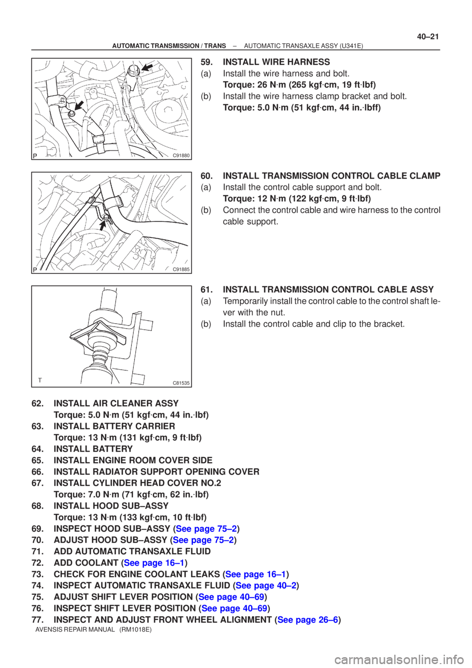
59. INSTALL WIRE HARNESS
(a) Install the wire harness and bolt.
Torque: 26 N �m (265 kgf �cm, 19 ft �lbf)
(b) Install the wire harness clamp bracket and bolt. Torque: 5.0 N �m (51 kgf �cm, 44 in. �lbff)
60. INSTALL TRANSMISSION CONTROL CABLE CLAMP
(a) Install the control cable support and bolt. Torque: 12 N �m (122 kgf �cm, 9 ft �lbf)
(b) Connect the control cable and wire harness to the control cable support.
61. INSTALL TRANSMISSION CONTROL CABLE ASSY
(a) Temporarily install the control cable to the control shaft le- ver with the nut.
(b) Install the control cable and clip to the bracket.
62. INSTALL AIR CLEANER ASSY Torque: 5.0 N �m (51 kgf �cm, 44 in. �lbf)
63. INSTALL BATTERY CARRIER Torque: 13 N �m (131 kgf �cm, 9 ft �lbf)
64. INSTALL BATTERY
65. INSTALL ENGINE ROOM COVER SIDE
66. INSTALL RADIATOR SUPPORT OPENING COVER
67. INSTALL CYLINDER HEAD COVER NO.2 Torque: 7.0 N �m (71 kgf �cm, 62 in. �lbf)
68. INSTALL HOOD SUB±ASSY Torque: 13 N �m (133 kgf �cm, 10 ft �lbf)
69.INSPECT HOOD SUB±ASSY (See page 75±2)
70.ADJUST HOOD SUB±ASSY (See page 75±2)
71. ADD AUTOMATIC TRANSAXLE FLUID
72.ADD COOLANT (See page 16±1)
73.CHECK FOR ENGINE COOLANT LEAKS (See page 16±1)
74.INSPECT AUTOMATIC TRANSAXLE FLUID (See page 40±2)
75.ADJUST SHIFT LEVER POSITION (See page 40±69)
76.INSPECT SHIFT LEVER POSITION (See page 40±69)
77.INSPECT AND ADJUST FRONT WHEEL ALIGNMENT (See page 26±6)