Page 2428 of 5135
160ME±01
A79148
SST
16±46
±
COOLING WATER PUMP ASSY(1CD±FTV)
AVENSIS REPAIR MANUAL (RM1018E)
WATER PUMP ASSY(1CD±FTV)
REPLACEMENT
1.REMOVE RADIATOR SUPPORT OPENING COVER
2.REMOVE ENGINE ROOM COVER SIDE
3.DRAIN ENGINE COOLANT(See page 16±44)
4.REMOVE FRONT WHEEL RH
5.REMOVE ENGINE UNDER COVER SUB±ASSY NO.1
6.REMOVE ENGINE UNDER COVER RH
7.REMOVE ENGINE COVER NO.1
(a)Remove the 5 nuts and the engine cover.
8.REMOVE INJECTOR DRIVER (See page 14±286)
9.REMOVE V (COOLER COMPRESSOR TO CRANKSHAFT PULLEY) BELT NO.1 (See page 14±269)
10.REMOVE GENERATOR V BELT (See page 14±269)
11.SEPARATE POWER STEERING IDLE PULLEY BRACKET (See page 14±286)
12.SEPARATE ENGINE MOUNTING INSULATOR SUB±ASSY RH(See page 14±307)
13.REMOVE CRANKSHAFT PULLEY(See page 14±307) SST 09213±54015 (90105±08076), 09330±00021, 09950±50013 (0995\
1±05010, 09952±05010, 09953±05020, 09954±05031)
14. REMOVE IDLER PULLEY SUB±ASSY
(a) Remove the bolt, the washer and the pulley.
15.REMOVE TIMING BELT NO.2 COVER(See page 14±307)
16.REMOVE TIMING BELT NO.1 COVER(See page 14±307)
17. REMOVE TIMING BELT GUIDE
18.REMOVE TRANSVERSE ENGINE ENGINE MOUNTING BRACKET(See page 14±307)
19.SET NO. 1 CYLINDER TO TDC/COMPRESSION(See page 14±307)
20.REMOVE TIMING CHAIN COVER PLATE(See page 14±307)
21.REMOVE TIMING BELT(See page 14±307)
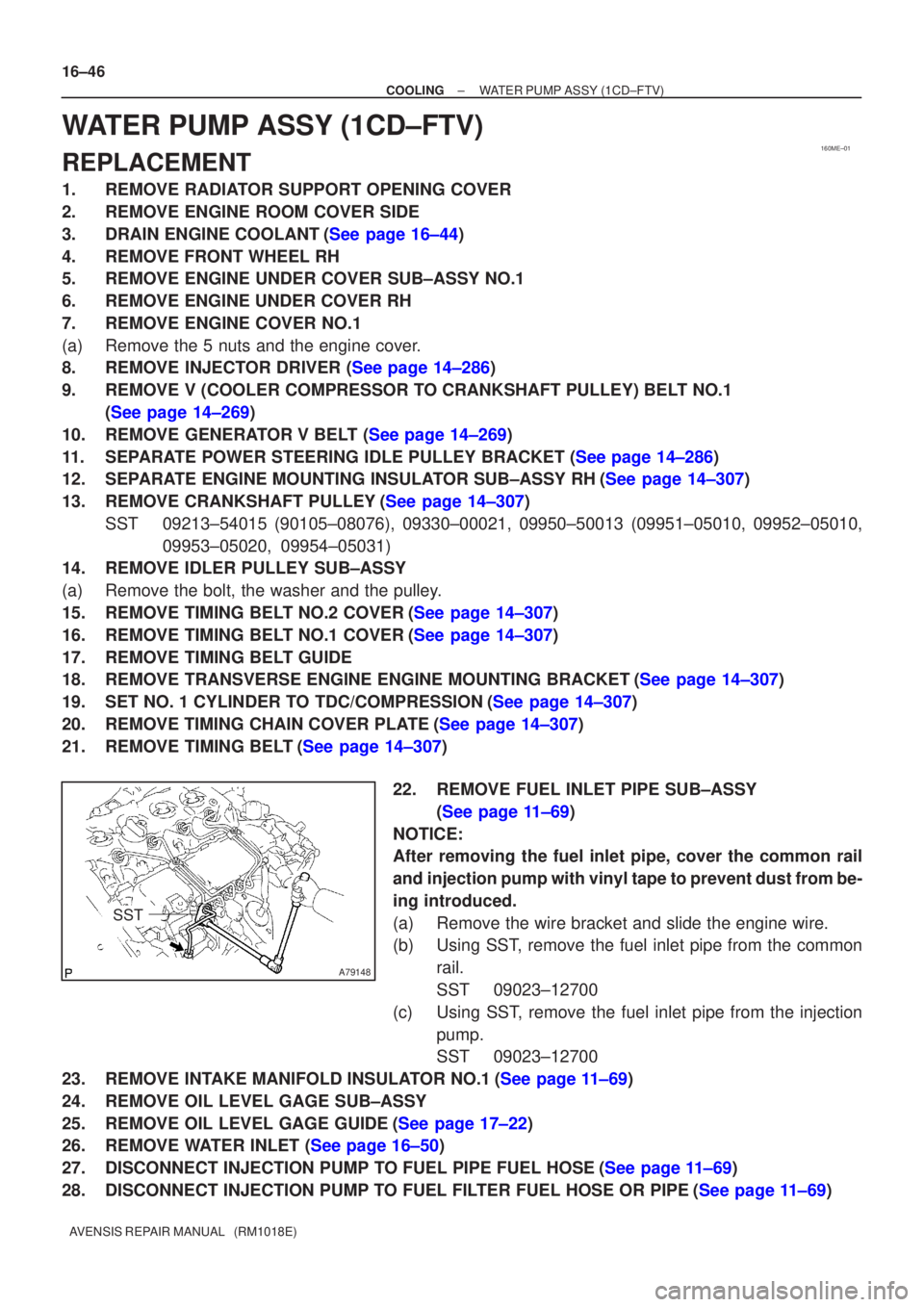
22. REMOVE FUEL INLET PIPE SUB±ASSY(See page 11±69)
NOTICE:
After removing the fuel inlet pipe, cover the common rail
and injection pump with vinyl tape to prevent dust from be-
ing introduced.
(a) Remove the wire bracket and slide the engine wire.
(b) Using SST, remove the fuel inlet pipe from the common rail.
SST 09023±12700
(c) Using SST, remove the fuel inlet pipe from the injection pump.
SST 09023±12700
23.REMOVE INTAKE MANIFOLD INSULATOR NO.1(See page 11±69)
24. REMOVE OIL LEVEL GAGE SUB±ASSY
25.REMOVE OIL LEVEL GAGE GUIDE(See page 17±22)
26.REMOVE WATER INLET (See page 16±50)
27.DISCONNECT INJECTION PUMP TO FUEL PIPE FUEL HOSE(See page 11±69)
28.DISCONNECT INJECTION PUMP TO FUEL FILTER FUEL HOSE OR PIPE(See page 11±69)
Page 2432 of 5135
190NI±01
A78487
(a)
(d)
(e)
(c)
Terminal Cap No. 2
A78488
A78488
A
B
±
STARTING & CHARGING GENERATOR ASSY(1ZZ±FE/3ZZ±FE)
19±7
AVENSIS REPAIR MANUAL (RM1018E)
GENERATOR ASSY(1ZZ±FE/3ZZ±FE)
REPLACEMENT
1.REMOVE ENGINE UNDER COVER SUB±ASSY NO.1 (See page 10±17)
2.REMOVE RADIATOR SUPPORT OPENING COVER (See page 10±9)
3.REMOVE ENGINE ROOM COVER SIDE (See page 10±9)
4.REMOVE FAN AND GENERATOR V BELT (See page 14±5)
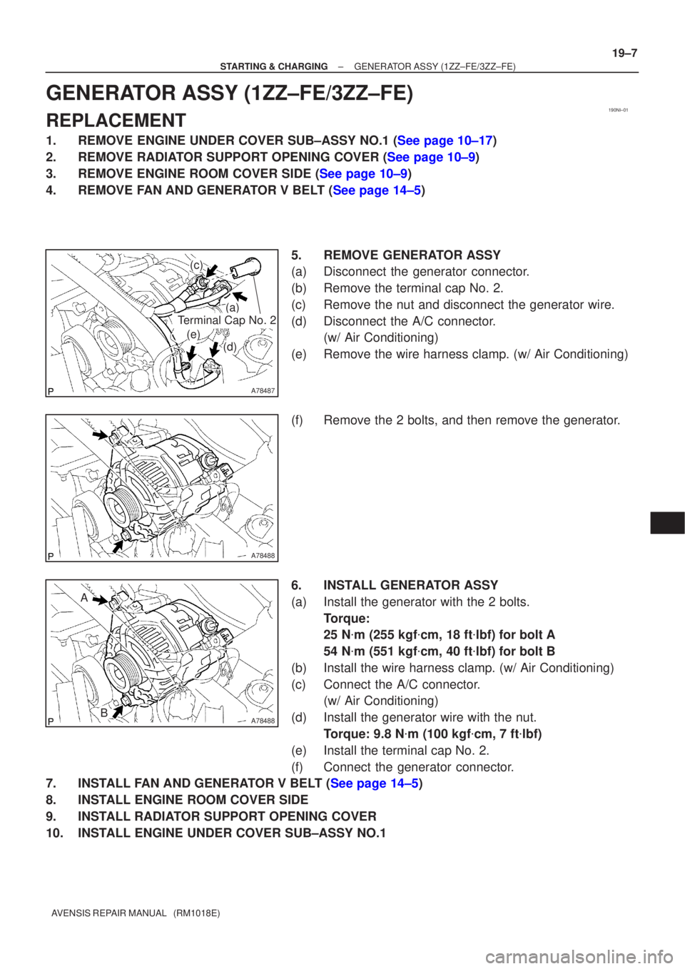
5.REMOVE GENERATOR ASSY
(a)Disconnect the generator connector.
(b)Remove the terminal cap No. 2.
(c)Remove the nut and disconnect the generator wire.
(d)Disconnect the A/C connector. (w/ Air Conditioning)
(e)Remove the wire harness clamp. (w/ Air Conditioning)
(f)Remove the 2 bolts, and then remove the generator.
6.INSTALL GENERATOR ASSY
(a)Install the generator with the 2 bolts. Torque:
25 N�m (255 kgf �cm, 18 ft �lbf) for bolt A
54 N �m (551 kgf �cm, 40 ft �lbf) for bolt B
(b)Install the wire harness clamp. (w/ Air Conditioning)
(c)Connect the A/C connector. (w/ Air Conditioning)
(d)Install the generator wire with the nut. Torque: 9.8 N �m (100 kgf �cm, 7 ft �lbf)
(e)Install the terminal cap No. 2.
(f)Connect the generator connector.
7.INSTALL FAN AND GENERATOR V BELT (See page 14±5)
8. INSTALL ENGINE ROOM COVER SIDE
9. INSTALL RADIATOR SUPPORT OPENING COVER
10. INSTALL ENGINE UNDER COVER SUB±ASSY NO.1
Page 2439 of 5135
1807L±01
A77896
(a)(b)
(c)
(d)
±
IGNITION CRANKSHAFT POSITION
SENSOR(1AZ±FE/1AZ±FSE)18±17
AVENSIS REPAIR MANUAL (RM1018E)
CRANKSHAFT POSITION SENSOR(1AZ±FE/1AZ±FSE)
REPLACEMENT
1.REMOVE ENGINE UNDER COVER LH (See page 19±20)
2.REMOVE ENGINE UNDER COVER RH (See page 19±20)
3.REMOVE RADIATOR SUPPORT OPENING COVER (See page 10±26)
4.REMOVE ENGINE ROOM COVER SIDE (See page 10±26)
5.REMOVE FAN AND GENERATOR V BELT
6.REMOVE GENERATOR ASSY (See page 19±20)
SST09249±63010
HINT:
�1AZ±FE: 14±105
�1AZ±FSE: 14±185
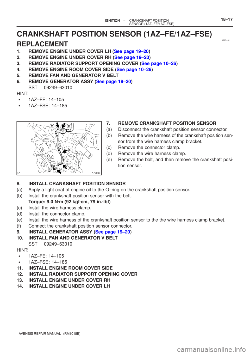
7.REMOVE CRANKSHAFT POSITION SENSOR
(a)Disconnect the crankshaft position sensor connector.
(b)Remove the wire harness of the crankshaft position sen-sor from the wire harness clamp bracket.
(c)Remove the connector clamp.
(d)Remove the wire harness clamp.
(e)Remove the bolt, and then remove the crankshaft posi-
tion sensor.
8.INSTALL CRANKSHAFT POSITION SENSOR
(a)Apply a light coat of engine oil to the O±ring on the crankshaft posi\
tion sensor.
(b)Install the crankshaft position sensor with the bolt. Torque: 9.0 N �m (92 kgf �cm, 79 in. �lbf)
(c)Install the wire harness clamp.
(d)Install the connector clamp.
(e)Install the wire harness of the crankshaft position sensor to the the wi\
re harness clamp bracket.
(f)Connect the crankshaft position sensor connector.
9.INSTALL GENERATOR ASSY (See page 19±20)
10. INSTALL FAN AND GENERATOR V BELT SST 09249±63010
HINT:
�1AZ±FE: 14±105
�1AZ±FSE: 14±185
11. INSTALL ENGINE ROOM COVER SIDE
12. INSTALL RADIATOR SUPPORT OPENING COVER
13. INSTALL ENGINE UNDER COVER RH
14. INSTALL ENGINE UNDER COVER LH
Page 2440 of 5135
1807K±01
A77895
18±16
±
IGNITION CAMSHAFT POSITION SENSOR(1AZ±FE/1AZ±FSE)
AVENSIS REPAIR MANUAL (RM1018E)
CAMSHAFT POSITION SENSOR(1AZ±FE/1AZ±FSE)
REPLACEMENT
1.REMOVE RADIATOR SUPPORT OPENING COVER (See page 10±26) 2. REMOVE CAMSHAFT POSITION SENSOR
(a) Disconnect the camshaft position sensor connector.
(b) Remove the bolt, and then remove the camshaft positionsensor.
3. INSTALL CAMSHAFT POSITION SENSOR
(a) Apply a light coat of engine oil to the O±ring on the camshaft positi\
on sensor.
(b) Install the camshaft position sensor with the bolt. Torque: 9.0 N �m (92 kgf �cm, 79 in. �lbf)
(c) Connect the camshaft position sensor connector.
4. INSTALL RADIATOR SUPPORT OPENING COVER
Page 2450 of 5135
1807J±01
A78483
(a)
(b)
A78484
(f)
(e)(d)
18±6
±
IGNITION CRANKSHAFT POSITION SENSOR(1ZZ±FE/3ZZ±FE)
AVENSIS REPAIR MANUAL (RM1018E)
CRANKSHAFT POSITION SENSOR(1ZZ±FE/3ZZ±FE)
REPLACEMENT
1.REMOVE ENGINE UNDER COVER LH (See page 19±20)
2.REMOVE ENGINE UNDER COVER SUB±ASSY NO.1 (See page 10±17)
3.REMOVE ENGINE UNDER COVER RH (See page 19±20)
4.REMOVE RADIATOR SUPPORT OPENING COVER (See page 10±9)
5.REMOVE ENGINE ROOM COVER SIDE (See page 10±9)
6.REMOVE FAN AND GENERATOR V BELT (See page 14±5)
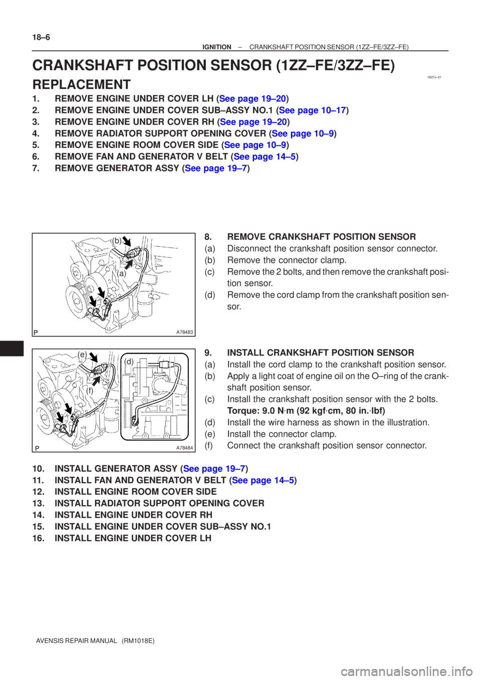
7.REMOVE GENERATOR ASSY (See page 19±7) 8.REMOVE CRANKSHAFT POSITION SENSOR
(a)Disconnect the crankshaft position sensor connector.
(b)Remove the connector clamp.
(c)Remove the 2 bolts, and then remove the crankshaft posi-tion sensor.
(d)Remove the cord clamp from the crankshaft position sen- sor.
9.INSTALL CRANKSHAFT POSITION SENSOR
(a)Install the cord clamp to the crankshaft position sensor.
(b)Apply a light coat of engine oil on the O±ring of the crank- shaft position sensor.
(c)Install the crankshaft position sensor with the 2 bolts. Torque: 9.0 N �m (92 kgf �cm, 80 in. �lbf)
(d)Install the wire harness as shown in the illustration.
(e)Install the connector clamp.
(f)Connect the crankshaft position sensor connector.
10.INSTALL GENERATOR ASSY (See page 19±7)
11.INSTALL FAN AND GENERATOR V BELT (See page 14±5)
12. INSTALL ENGINE ROOM COVER SIDE
13. INSTALL RADIATOR SUPPORT OPENING COVER
14. INSTALL ENGINE UNDER COVER RH
15. INSTALL ENGINE UNDER COVER SUB±ASSY NO.1
16. INSTALL ENGINE UNDER COVER LH
Page 2451 of 5135
1807I±01
A78482
±
IGNITION CAMSHAFT POSITION SENSOR(1ZZ±FE/3ZZ±FE)
18±5
AVENSIS REPAIR MANUAL (RM1018E)
CAMSHAFT POSITION SENSOR(1ZZ±FE/3ZZ±FE)
REPLACEMENT
1.REMOVE RADIATOR SUPPORT OPENING COVER (See page 10±9)
2.REMOVE CYLINDER HEAD COVER NO.2 (See page 10±9)
3.REMOVE CAMSHAFT POSITION SENSOR
(a)Disconnect the camshaft position sensor connector.
(b)Remove the bolt, and then remove the camshaft positionsensor.
4.INSTALL CAMSHAFT POSITION SENSOR
(a)Apply a light coat of engine oil to the O±ring on the camshaft positi\
on sensor.
(b)Install the camshaft position sensor with the bolt. Torque: 9.0 N �m (92 kgf �cm, 80 in. �lbf)
(c)Connect the camshaft position sensor connector.
5.INSTALL CYLINDER HEAD COVER NO.2 (See page 10±9)
6. INSTALL RADIATOR SUPPORT OPENING COVER
Page 2468 of 5135
190O1±01
A79176
±
STARTING & CHARGING GENERATOR ASSY(1CD±FTV)
19±29
AVENSIS REPAIR MANUAL (RM1018E)
GENERATOR ASSY(1CD±FTV)
REPLACEMENT
1.REMOVE FRONT WHEEL RH
2.REMOVE RADIATOR SUPPORT OPENING COVER
3.REMOVE ENGINE ROOM COVER SIDE
4.REMOVE ENGINE UNDER COVER SUB±ASSY NO.1
5.REMOVE ENGINE UNDER COVER RH
6.REMOVE V (COOLER COMPRESSOR TO CRANKSHAFT PULLEY) BELT NO.1
(See page 14±269)
7.REMOVE GENERATOR V BELT (See page 14±269)
8.REMOVE FLOOR PANEL BRACE FRONT(See page 15±10)
9.REMOVE EXHAUST PIPE ASSY FRONT(See page 15±10)
10.REMOVE EXHAUST PIPE ASSY (W/ COLD AREA) (See page 13±11)
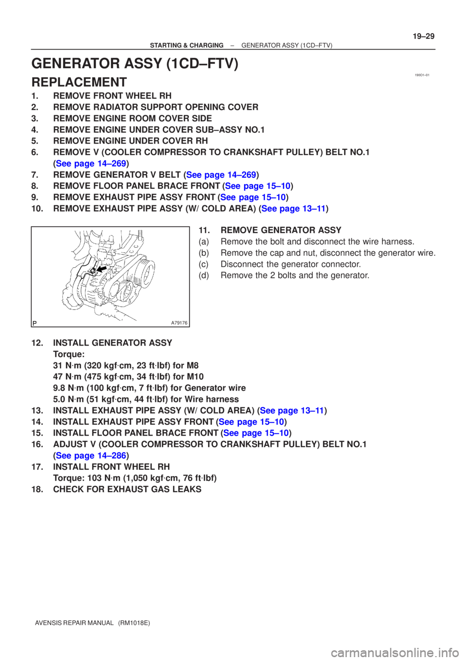
11.REMOVE GENERATOR ASSY
(a)Remove the bolt and disconnect the wire harness.
(b)Remove the cap and nut, disconnect the generator wire.
(c)Disconnect the generator connector.
(d)Remove the 2 bolts and the generator.
12.INSTALL GENERATOR ASSY Torque:
31 N�m (320 kgf �cm, 23 ft �lbf) for M8
47 N �m (475 kgf �cm, 34 ft �lbf) for M10
9.8 N �m (100 kgf �cm, 7 ft �lbf) for Generator wire
5.0 N �m (51 kgf �cm, 44 ft �lbf) for Wire harness
13.INSTALL EXHAUST PIPE ASSY (W/ COLD AREA) (See page 13±11)
14.INSTALL EXHAUST PIPE ASSY FRONT(See page 15±10)
15.INSTALL FLOOR PANEL BRACE FRONT(See page 15±10)
16. ADJUST V (COOLER COMPRESSOR TO CRANKSHAFT PULLEY) BELT NO.1 (See page 14±286)
17. INSTALL FRONT WHEEL RH Torque: 103 N �m (1,050 kgf �cm, 76 ft �lbf)
18. CHECK FOR EXHAUST GAS LEAKS
Page 2473 of 5135
190O0±01
19±24
±
STARTING & CHARGING STARTER ASSY(1CD±FTV)
AVENSIS REPAIR MANUAL (RM1018E)
STARTER ASSY(1CD±FTV)
REPLACEMENT
1.DRAIN ENGINE COOLANT(See page 16±44)
2.REMOVE RADIATOR SUPPORT OPENING COVER
3.REMOVE RADIATOR RESERVE TANK ASSY(See page 16±50)
4.REMOVE AIR CLEANER ASSY (See page 14±286)
5.REMOVE BATTERY
6.REMOVE STARTER ASSY
(a)Remove the nut and disconnect terminal 30.
(b)Disconnect the starter connector.
(c)Remove the 2 bolts and the starter.
7.INSTALL STARTER ASSY Torque:
37 N�m (377 kgf �cm, 27 ft �lbf) for bolt
9.8 N �m (100 kgf �cm, 7.2 ft �lbf) for terminal 30
8.INSTALL AIR CLEANER ASSY (See page 14±286)
9.INSTALL RADIATOR RESERVE TANK ASSY(See page 16±50)
10.ADD ENGINE COOLANT(See page 16±44)
11.CHECK FOR ENGINE COOLANT LEAKS(See page 16±44)