Page 1726 of 5135

PRE±CHECK
1. MULTIPLEX COMMUNICATION SYSTEM (BEAN)
(a) The BEAN communication line is used to control")
05AEP±02
± DIAGNOSTICSMULTIPLEX COMMUNICATION SYSTEM
05±1655
AVENSIS REPAIR MANUAL (RM1018E)
PRE±CHECK
1. MULTIPLEX COMMUNICATION SYSTEM (BEAN)
(a) The BEAN communication line is used to control the ECM, the A/C control assy (A/C ECU), the com-
bination meter assy (combination meter ECU) and the theft warning ECU, which are connected to the
instrument panel J/B assy (integration relay). If there is a short±circuit (bus±down) in the line, the com-
munication to the system that has a short±circuit (bus±down)will be disabled and the DTC concerning
the system will be output from the instrument panel J/B assy (integration relay).
2. CHECK COMMUNICATION FUNCTION
(a) Check the battery voltage.
Standard: 10 to 14 V
(b) Inspect the DTC output.
(1) Check a DTC for the instrument panel J/B assy (integration relay) by connecting the hand±held
tester to the DLC3 and turning the ignition switch ON.
HINT:
�When DTC check is impossible, check the following items.
�The display shows communication error (refer to new diagnostic system and the operations when an
error occurrs.)
(2) When the display shows DTCs of the ECU unconnected and the communication bus defective,
perform the inspection depending on the type of troubleshooting.
HINT:
If another DTC is output, refer to the DTC chart and check the applicable section.
Page 1727 of 5135
05AEO±02
05±1654
±
DIAGNOSTICS MULTIPLEX COMMUNICATION SYSTEM
AVENSIS REPAIR MANUAL (RM1018E)
MULTIPLEX COMMUNICATION SYSTEM
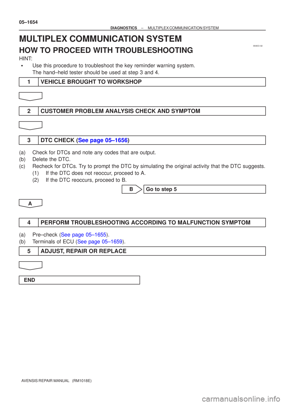
HOW TO PROCEED WITH TROUBLESHOOTING
HINT:
�Use this procedure to troubleshoot the key reminder warning system.
The hand±held tester should be used at step 3 and 4.
1VEHICLE BROUGHT TO WORKSHOP
2CUSTOMER PROBLEM ANALYSIS CHECK AND SYMPTOM
3DTC CHECK (See page 05±1656)
(a)Check for DTCs and note any codes that are output.
(b)Delete the DTC.
(c)Recheck for DTCs. Try to prompt the DTC by simulating the original activity that the DTC su\
ggests. (1)If the DTC does not reoccur, proceed to A.
(2)If the DTC reoccurs, proceed to B.
BGo to step 5
A
4PERFORM TROUBLESHOOTING ACCORDING TO MALFUNCTION SYMPTOM
(a)Pre±check (See page 05±1655).
(b)Terminals of ECU (See page 05±1659).
5 ADJUST, REPAIR OR REPLACE
END
Page 1728 of 5135

T13
Rear Theft Warning
Radar")
B67699
S+B
IOUT 24
26 L±W
L±B 9 T12
Theft Warning Radar Sensor
6 S+B
IOUT
SOFF7
W±BSSW1
13 LG±B
ID18T6
Theft Warning ECU Assy
T14
Rear Theft Warning
Radar Sensor (IN)
T13
Rear Theft Warning
Radar Sensor (OUT)
IJ DA DK9 6 LG±B L±B L±W
ID1 ID1
W±B 19
SOU+
SOU±GND SIN+
SIN± 2
1
2
18
4
1 53 W
P
L
2 MIN+
MIN±
MOU+
MOU±Instrument Panel J/B Assy Shielded 05±1650
± DIAGNOSTICSTHEFT DETERRENT SYSTEM
AVENSIS REPAIR MANUAL (RM1018E)
INTRUSION SENSOR CIRCUIT
CIRCUIT DESCRIPTION
The intrusion sensor (theft warning radar sensor) senses any moving object by using ultrasonic waves and
outputs the signals to inform the theft warning ECU of an intrusion, so that the theft deterrent system can
set off the alarm.
When the theft deterrent system is switched to the arming preparation state, the intrusion sensor is supplied
with S+B by the theft warning ECU. This causes the theft deterrent system to set off the alarm when the signal
is input from the intrusion sensor in a situation such as when the window glass is broken.
WIRING DIAGRAM
05BAH±01
Page 1729 of 5135

LOW
(0.2 ± 0.8 V)T1: 0.2 sec.
T2: 0.1 sec.
T1T2
± DIAGNOSTICSTHEFT DETERRENT SYSTEM
05±1651
AVENSIS REPAIR MANUAL (RM101")
B67866
T12
Theft Warning Radar Sensor
1 2 4
87653
B69135
HIGH
(10 ± 14 V)
LOW
(0.2 ± 0.8 V)T1: 0.2 sec.
T2: 0.1 sec.
T1T2
± DIAGNOSTICSTHEFT DETERRENT SYSTEM
05±1651
AVENSIS REPAIR MANUAL (RM1018E)
INSPECTION PROCEDURE
1 CHECK THEFT WARNING RADAR SENSOR (OPERATION)
(a) Set the theft deterrent system with a window open and after 30 seconds insert your hand through the
window and shake it near the sensor to check if the alarm is triggered.
OK NO PROBLEM
NG
2 CHECK THEFT WARNING RADAR SENSOR (VOLTAGE, RESISTANCE)
(a) Check the voltage or resistance between each terminal of
the connector and the body ground.
Tester ConnectionConditionSpecified Condition
T12±7 (S+B) ±
Body ground
Arming preparation state
or armed state10 to 14 V
Body groundDisarmed stateBelow 1 V
When sensor does not de-
tect any movement10 to 14 V
T12±6 (IOUT) ±
Body groundWhen sensor detects
movement when in arming
preparation state or armed
state
Using an oscilloscope *2
T12±3 (SOFF) ± OFF Switch ONBelow 1 �T12 3 (SOFF)
Body ground
OFF Switch OFF10 k� or higher
T12±2 (GND) ±
Body groundConstantBelow 1 �
*1
T12±8 (SIN+) ±
T12±4 (SIN±)Disarmed state5 ± 10 k�
*1
T12±1 (SOU+) ±
T12±5 (SOU±)Disarmed state1 M� or higher
HINT:
*
1: Wagon only
Wave pattern (*
2):
NG REPLACE THEFT WARNING RADAR SENSOR
OK
Page 1730 of 5135
B67867
1 2
������
������B68491
Wire Harness Side
T6
Theft Warning ECU Assy
T12
Theft Warning Radar Sensor
05±1652
± DIAGNOSTICSTHEFT DETERRENT SYSTEM
AVENSIS REPAIR MANUAL (RM1018E)
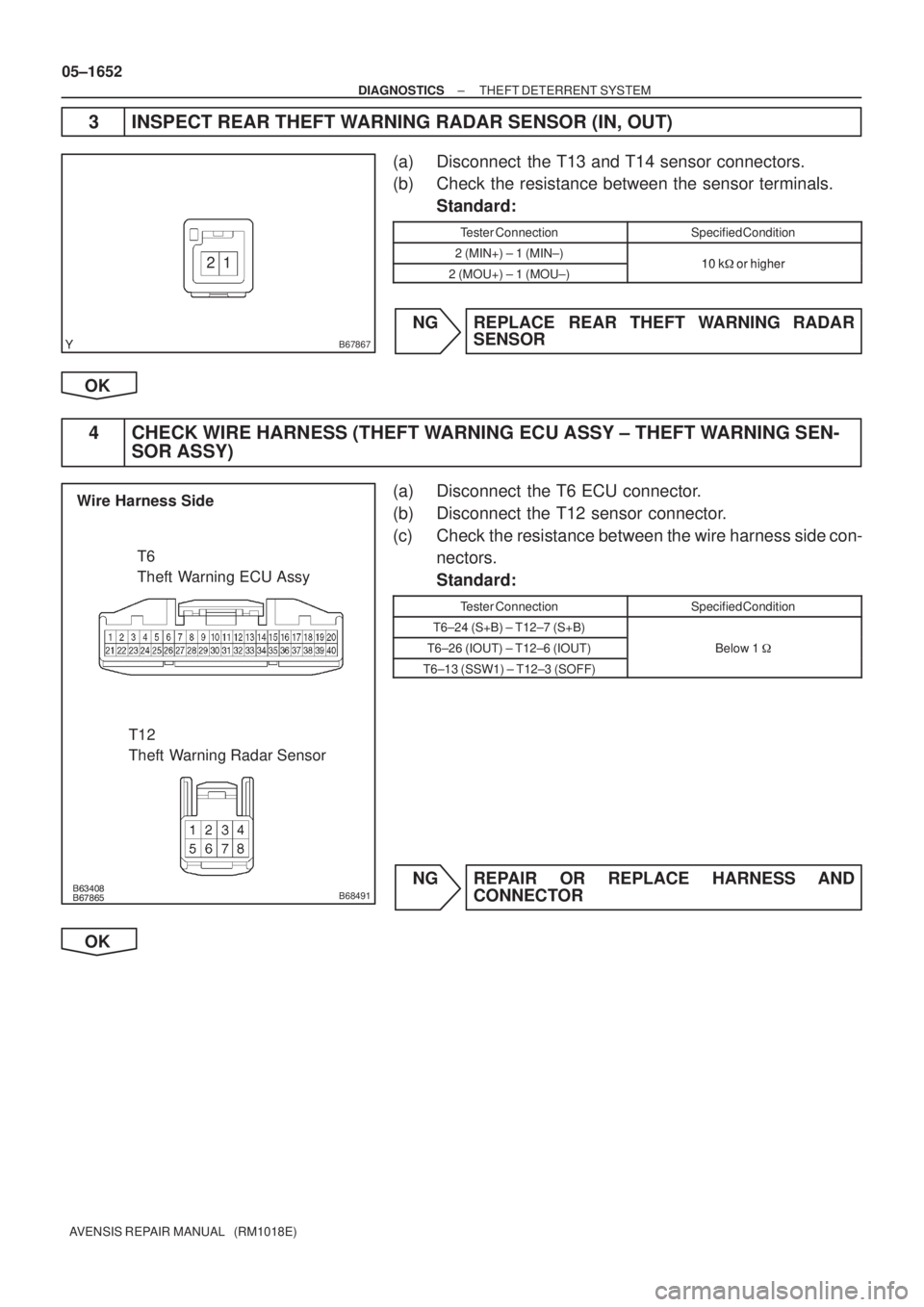
3 INSPECT REAR THEFT WARNING RADAR SENSOR (IN, OUT)
(a) Disconnect the T13 and T14 sensor connectors.
(b) Check the resistance between the sensor terminals.
Standard:
Tester ConnectionSpecified Condition
2 (MIN+) ± 1 (MIN±)10 k�or higher2 (MOU+) ± 1 (MOU±)10 k� or higher
NG REPLACE REAR THEFT WARNING RADAR
SENSOR
OK
4 CHECK WIRE HARNESS (THEFT WARNING ECU ASSY ± THEFT WARNING SEN-
SOR ASSY)
(a) Disconnect the T6 ECU connector.
(b) Disconnect the T12 sensor connector.
(c) Check the resistance between the wire harness side con-
nectors.
Standard:
Tester ConnectionSpecified Condition
T6±24 (S+B) ± T12±7 (S+B)
T6±26 (IOUT) ± T12±6 (IOUT)Below 1 �
T6±13 (SSW1) ± T12±3 (SOFF)
NG REPAIR OR REPLACE HARNESS AND
CONNECTOR
OK
Page 1731 of 5135

������
������B68492
Wire Harness Side
T12
Theft Warning Radar Sensor
T13
T14
Rear Theft Warning Radar Sensor
B67865
Wire Harness Side
T12
Theft Warning Radar Sensor
± DIAGNOSTICSTHEFT DETERRENT SYSTEM
05±1653
AVENSIS REPAIR MANUAL (RM1018E)
5 CHECK WIRE HARNESS (THEFT WARNING SENSOR ASSY ± REAR THEFT
WARNING SENSOR ASSY (IN, OUT))
(a) Disconnect the T12, T13 and T14 sensor connectors.
(b) Check the resistance between the wire harness side con-
nectors.
Standard:
Tester ConnectionSpecified Condition
T12±5 (SOU+) ± T13±2 (MOU+)
T12±1 (SOU±) ± T13±1 (MOU±)Below 1�T12±8 (SIN+) ± T14±2 (MIN+)Below 1 �
T12±4 (SIN±) ± T14±1 (MIN±)
NG REPAIR OR REPLACE HARNESS AND
CONNECTOR
OK
6 CHECK WIRE HARNESS (THEFT WARNING RADAR SENSOR ± BODY GROUND)
(a) Disconnect the T12 sensor connector.
(b) Check the resistance between the wire harness side con-
nector and the body ground.
Standard:
Tester ConnectionSpecified Condition
T12±2 (GND) ± Body groundBelow 1 �
NG REPAIR OR REPLACE HARNESS AND
CONNECTOR
OK
REPLACE THEFT WARNING ECU ASSY
Page 1732 of 5135

B67700
CTLS
27 L±R
IM111 T15
Theft Warning Siren Assy
W±R
CI CC7
2
2
4AECU±B2 Fuse Block 10
1 W±R
B*
2
Battery Center J/B Assy
6T6
Theft Warning ECU Assy
BW
+B
3 W±R
B±G*
1
L±R
IM112
GND CONT
6
IP15
B±W B±W
Engine Room R/B
DCC
1 21
1 1A
B*
2B±G*1
4B
Main3
3 11W±B
*
1: Gasoline
*2: 1CD±FTV1
Engine Room
R/B No. 3 Engine Room
J/B No. 4
± DIAGNOSTICSTHEFT DETERRENT SYSTEM
05±1647
AVENSIS REPAIR MANUAL (RM1018E)
THEFT WARNING SIREN CIRCUIT
CIRCUIT DESCRIPTION
The theft warning siren has an internal battery. If any of the vehicle's battery or communication line is opened,
the theft warning siren detects it by itself and sounds. Although the theft warning siren sounds by receiving
a signal from the theft deterrent ECU usually, the theft warning siren can sound by its internal battery in case
that the vehicle's battery is opened.
The theft deterrent ECU sends an arming signal to the theft warning siren while transferring to the armed
state, and it also sends a disarming signal to the siren while transferring to the disarmed state. Besides, the
theft deterrent ECU can cause the theft warning siren to sound by sending an alarm signal in the alarm
sounding state.
WIRING DIAGRAM
05BAG±01
Page 1733 of 5135

HIGH
(6.5 V or more) LOW
(Below 1.0 V)
LOW
(Below 1.0 V)T1: 0.4 sec.
T2: 0.1 sec.
T3: 0.2 sec. T1
T2
T3
T1
T3")
B67858
T15
Theft Warning Siren Assy
*1: Wave Pattern
*
2: Wave PatternHIGH
(6.5 V or more)
HIGH
(6.5 V or more) LOW
(Below 1.0 V)
LOW
(Below 1.0 V)T1: 0.4 sec.
T2: 0.1 sec.
T3: 0.2 sec. T1
T2
T3
T1
T3T3
T2
T2
05±1648
± DIAGNOSTICSTHEFT DETERRENT SYSTEM
AVENSIS REPAIR MANUAL (RM1018E)
INSPECTION PROCEDURE
1 INSPECT FUSE (ECU±B2, DCC)
(a) Remove the ECU±B2 fuse from the fuse block.
(b) Remove the DCC fuse from the engine room R/B.
(c) Check the resistance.
Standard: Resistance
NG REPLACE FUSE
OK
2 CHECK THEFT WARNING SIREN ASSY
(a) Check the voltage between each terminal of the connec-
tor and the body ground.
Standard:
Tester ConnectionConditionSpecified Condition
T15±1 (+B) ±
Body groundConstant10 to 14 V
T15±2 (GND) ±
Body groundConstantBelow 1 V
When switched from
armed state or arming
preparation state to dis-
armed state (1)
Using an oscilloscope*1
T15±3 (CONT) ±
Body groundWhen switched from arm-
ing preparation state to
armed state (2)
Using an oscilloscope*2
Normal condition
(Except (1) and (2))Approx. 1.4 V
Wave pattern:
NG REPLACE THEFT WARNING SIREN ASSY
OK