Page 1671 of 5135
05BA8±01
������
������B68543
Rear Window Defogger
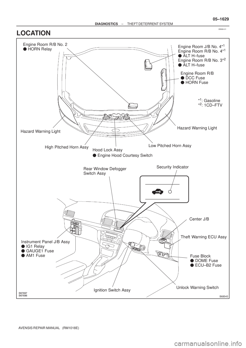
Switch AssyEngine Room R/B
� DCC Fuse
� HORN Fuse
Fuse Block
� DOME Fuse
� ECU±B2 Fuse
Center J/B
Security Indicator
Engine Room J/B No. 4*1
Engine Room R/B No. 4*1
� ALT H±fuse
Engine Room R/B No. 3*2
� ALT H±fuse
Engine Room R/B No. 2
� HORN Relay
High Pitched Horn AssyLow Pitched Horn AssyHazard Warning Light
Hazard Warning Light
Instrument Panel J/B Assy
� IG1 Relay
� GAUGE1 Fuse
� AM1 FuseHood Lock Assy
� Engine Hood Courtesy Switch
Theft Warning ECU Assy
Unlock Warning Switch
Ignition Switch Assy*
1: Gasoline
*2: 1CD±FTV
± DIAGNOSTICSTHEFT DETERRENT SYSTEM
05±1629
AVENSIS REPAIR MANUAL (RM1018E)
LOCATION
Page 1672 of 5135
B67698
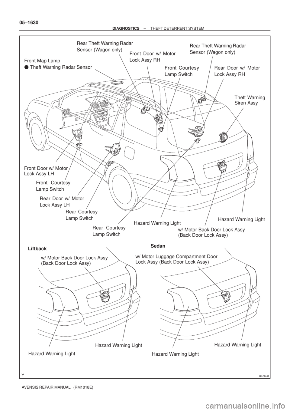
Front Map Lamp
� Theft Warning Radar Sensor
Hazard Warning LightHazard Warning Light
Hazard Warning Light
Hazard Warning LightHazard Warning Light
Hazard Warning Light
LiftbackSedanFront Courtesy
Lamp Switch Front Door w/ Motor
Lock Assy RH
Front Door w/ Motor
Lock Assy LH
Front Courtesy
Lamp Switch
w/ Motor Back Door Lock Assy
(Back Door Lock Assy)Theft Warning
Siren Assy
w/ Motor Luggage Compartment Door
Lock Assy (Back Door Lock Assy)
Rear Courtesy
Lamp Switch Rear Door w/ Motor
Lock Assy LHRear Theft Warning Radar
Sensor (Wagon only)
Rear Theft Warning Radar
Sensor (Wagon only)
Rear Door w/ Motor
Lock Assy RH
Rear Courtesy
Lamp Switch
w/ Motor Back Door Lock Assy
(Back Door Lock Assy) 05±1630
± DIAGNOSTICSTHEFT DETERRENT SYSTEM
AVENSIS REPAIR MANUAL (RM1018E)
Page 1673 of 5135

05BA7±01
THEFT DETERRENT SYSTEM Check SheetInspector 's name:
Customer 's Name
Date VehicleVIN
Production Date
Licence No.
Odometer Reading / /km
miles
Weather Conditions
When Problem
Occurred Frequency Problem OccursWeather
Outdoor
Temperature
/ /
� Constant � Sometimes ( Times per day, month)
� Once only Brought in
�
Security indicator light does not flash when theft deterrent system is set.
(It stays ON or does not light up at all)
Theft deterrent system
does not operate.When door is opened.
Theft deterrent system
cannot be canceled once
set.�
Theft deterrent system
cannot be canceled during
warning operation.When key is inserted into ignition key cylinder and ignition switch is turned
ON±OFF 10 times within 15 seconds.
Warning operation does not start when theft deterrent system is set and door is opened with key.
�
Date Problem First Occurred
� Fine � Cloudy � Rainy � Snowy
� Various/Others
� Hot � Warm � Cool
� Cold (Approx. �C ( �F))
Problem Symptom
�
�
�
�
� �Malfunction
� Horns only
� Door lock operation only
� Hazard warning light only
� Room lamp only
� Theft warning siren only
� Intrusion sensor only �
�When door is unlocked using wireless door lock control system. When engine hood is
opened.
When door is unlocked using wireless door lock control system.
Others �Theft deterrent system cannot be set. 05±1628
± DIAGNOSTICSTHEFT DETERRENT SYSTEM
AVENSIS REPAIR MANUAL (RM1018E)
CUSTOMER PROBLEM ANALYSIS CHECK
Page 1686 of 5135
B66226
T8
Transponder Key ECU Assy
10KSW
12 U1
Un±lock Warning
Switch Assy
IO: Gasoline
IL: 1CD±FTV J16
J/C W±BW±B
Y
J22F
J23 DJ/C
AY
W±B*
1
W±B*2
*1: LHD
*2: RHD IP CA 6CF 13
Center J/BY*
2
DA 6
DA8
Y*
1
Driver Side J/B*1
Passenger Side R/B Assy*2
Y*1
Y*2
W±BA
± DIAGNOSTICSENGINE IMMOBILISER SYSTEM
05±1613
AVENSIS REPAIR MANUAL (RM1018E)
DTC B2780 PUSH SWITCH/KEY UNLOCK WARNING
SWITCH MALFUNCTION
CIRCUIT DESCRIPTION
This DTC will be output if the transponder key ECU does not detect that the unlock warning switch is ON
even when the ignition switch is ON (Under normal conditions, the unlock warning switch is ON when the
ignition switch is ON).
DTC No.DTC Detection ConditionTrouble Area
B2780Unlock warning switch ON is not detected when ignition
switch is ON�Unlock warning switch assy
�Wire harness
�Transponder key ECU assy
WIRING DIAGRAM
05B0C±03
Page 1687 of 5135
B51903
PushedFree
05±1614
± DIAGNOSTICSENGINE IMMOBILISER SYSTEM
AVENSIS REPAIR MANUAL (RM1018E)
INSPECTION PROCEDURE
HINT:
Start the inspection from step 1 when using the hand±held tester and start from step 2 when not using the
hand±held tester.
1 READ VALUE OF HAND±HELD TESTER
(TRANSPONDER KEY ECU (SWITCH CONDITION))
(a) Connect the hand±held tester to the DLC3.
(b) Turn the ignition switch ON with the key that will not start the engine.
(c) Select the item KEY SW on the hand±held tester.
OK:
OFF � Key is in ignition key cylinder
ON � No key is in ignition key cylinder
OK REPLACE TRANSPONDER KEY ECU ASSY
NG
2 INSPECT UNLOCK WARNING SWITCH ASSY
(a) Remove the unlock warning switch.
(b) Inspect the unlock warning switch resistance.
Standard:
Tester ConnectionSwitch PositionSpecified Condition
12
Switch pushed
(Key set)Below 1 �
1 ± 2Switch free
(Key removed)10 k� or higher
NG REPLACE UNLOCK WARNING SWITCH ASSY
OK
Page 1688 of 5135
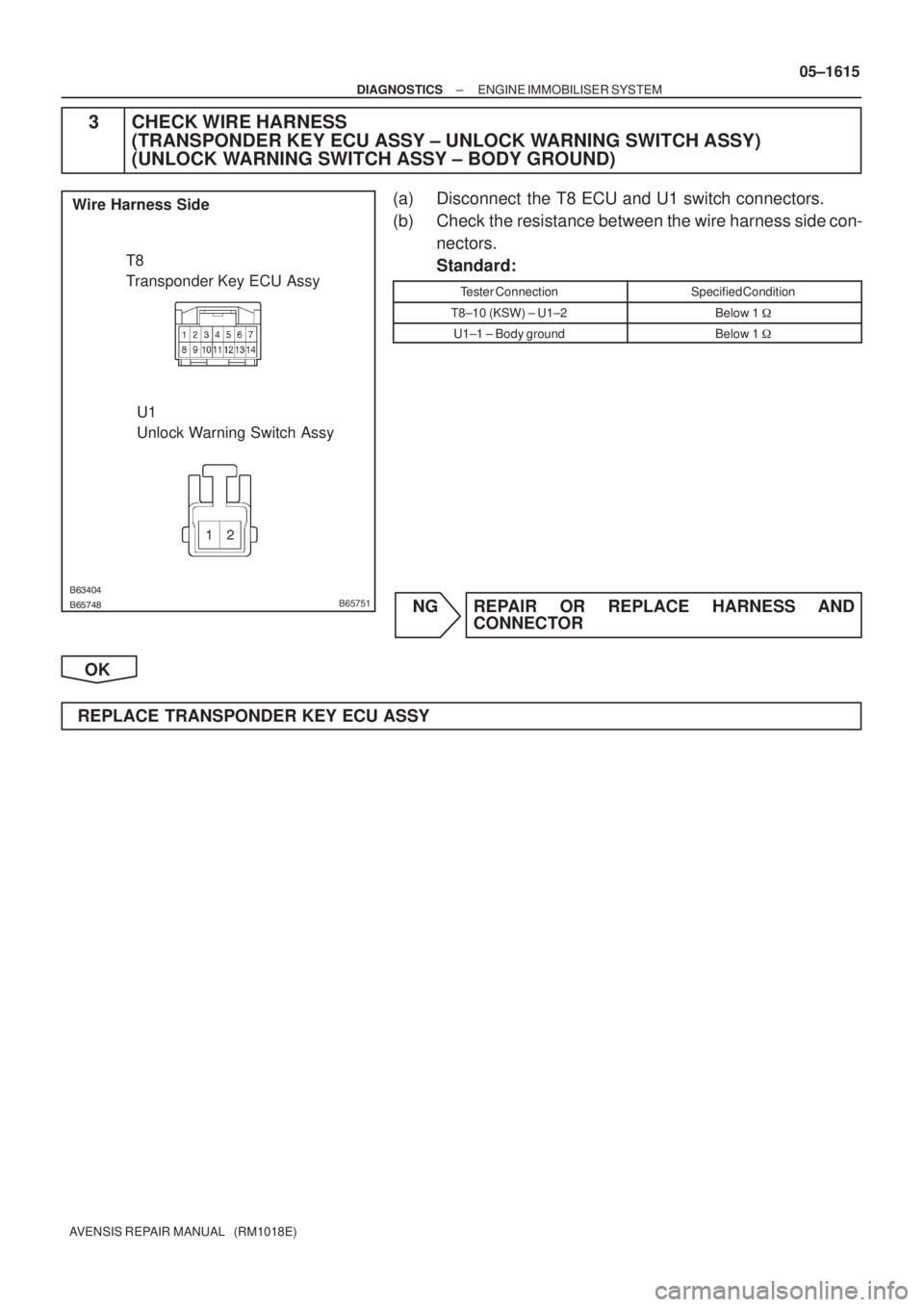
������������B65751
T8
Transponder Key ECU Assy
U1
Unlock Warning Switch Assy Wire Harness Side
± DIAGNOSTICSENGINE IMMOBILISER SYSTEM
05±1615
AVENSIS REPAIR MANUAL (RM1018E)
3 CHECK WIRE HARNESS
(TRANSPONDER KEY ECU ASSY ± UNLOCK WARNING SWITCH ASSY)
(UNLOCK WARNING SWITCH ASSY ± BODY GROUND)
(a) Disconnect the T8 ECU and U1 switch connectors.
(b) Check the resistance between the wire harness side con-
nectors.
Standard:
Tester ConnectionSpecified Condition
T8±10 (KSW) ± U1±2Below 1 �
U1±1 ± Body groundBelow 1 �
NG REPAIR OR REPLACE HARNESS AND
CONNECTOR
OK
REPLACE TRANSPONDER KEY ECU ASSY
Page 1689 of 5135
± DIAGNOSTICSMULTIPLEX COMMUNICATION SYSTEM
05±1689
AVENSIS REPAIR MANUAL (RM1018E)
DTC B1269 THEFT DETERRENT ECU COMMUNICATION
STOP
CIRCUIT DESCRIPTION
DTC B1269 is output when communication between the theft warning ECU and the combination meter stops
for more than 10 seconds.
DTC No.DTC Detection ConditionTrouble Area
B1269No communication from theft deterrent ECU for more than
10 seconds�Theft warning ECU assy
�Wire harness
05AEV±02
Page 1690 of 5135
B67807
Main
Battery 131
+B1MPX
E Theft Warning ECU Assy
B*
2
2H 5J/C
IP2 T6
W±R
B±G*
1
1A6
T6 IP1
B±W
CG B±W
1
*
1: Except 1CD±FTV
*2: 1CD±FTV BEAN
(SECURITY)
3W±B 1Combination Meter Assy
(Combination Meter ECU)
P±L
C1015
J27
J26F
W±R
6
1 DOME
2
T6 29
CA9
6
W±B *
2
B
*1
B±G
4A
4B
31
1
Engine Room J/B No. 4*1
Engine Room R/B
Engine Room
R/B No. 3*
2
Center J/B Fuse Block Assy
DCC 05±1690
± DIAGNOSTICSMULTIPLEX COMMUNICATION SYSTEM
AVENSIS REPAIR MANUAL (RM1018E)
WIRING DIAGRAM


INSPECTION PROCEDURE
HINT:
Start the inspection from step 1 when using the hand±held tester and st")

DTC B1269 THEFT DETERRENT ECU COMMUNICATION
STOP
CIRCUIT DESCRIPTION
DTC B1269 is output when communication betw")

3W±B 1Combination Meter Assy
(Com")