Page 1613 of 5135
B66819
DCTY
Integration Relay
KSW 13
DB D9
Front Door Courtesy Lamp Switch Assy
(Driver Side)
128
DA U1
Unlock Warning Switch AssyInstrument Panel J/B Assy
1 LHD models
R14
IC2J10
J/C
B
Y W±B J16
J/C
A
*
2: 1CD±FTVB
RR
A
IO*
1
IL*2
*1: Gasoline
W±B17
19
± DIAGNOSTICSPOWER DOOR LOCK CONTROL SYSTEM
05±1555
AVENSIS REPAIR MANUAL (RM1018E)
KEY LOCK±IN PREVENTION FUNCTION DOES NOT WORK
PROPERLY (MANUAL OPERATION AND OPERATION
INTERLOCKED WITH KEY ARE ACTIVE)
CIRCUIT DESCRIPTION
The unlock warning switch turns ON when the key is inserted into the ignition key cylinder. The courtesy
lamp switch turns ON when the driver side door is opened. These 2 switches are monitored by the integration
relay. In order to prevent the key from being locked in, the integration relay controls door locking operation
according to the conditions of these switches so that the doors are not locked with the key locked in.
WIRING DIAGRAM
05C8C±01
Page 1614 of 5135
B66820
DCTY
Integration Relay
KSW 13
DB D10
Front Door Courtesy Lamp Switch Assy
(Driver Side)
128
DA
U1
Unlock Warning
Switch AssyInstrument Panel J/B Assy
1 RHD models
1
RR
W±B135
6 9
W±B IM1CA CE
CF
IPCA
Y*2
J22
J/C
*
1: 1AZ±FE
*2: Except 1AZ±FER
17
19 Y*
2DD
Y*
1
Center J/B 05±1556
± DIAGNOSTICSPOWER DOOR LOCK CONTROL SYSTEM
AVENSIS REPAIR MANUAL (RM1018E)
Page 1615 of 5135
B51903
Pushed Free
Pin
± DIAGNOSTICSPOWER DOOR LOCK CONTROL SYSTEM
05±1557
AVENSIS REPAIR MANUAL (RM1018E)
INSPECTION PROCEDURE
1 READ VALUE OF HAND±HELD TESTER
(a) Using the hand±held tester, check that the unlock warning switch signal is output when the switch is
operated.
Standard (Integration relay):
ItemMeasurement Item/Display (Range)Normal ConditionDiagnostic
Note
KEY UNLK WRN SWUnlock warning switch signal
/ON or OFFON: Key is in ignition key cylinder
OFF: No key is in ignition key cylinder±
OK Go to step 4
NG
2 INSPECT UNLOCK WARNING SWITCH ASSY
(a) Remove the unlock warning switch.
(b) Inspect the resistance of the switch.
Standard:
Tester ConnectionSwitch PositionSpecified Condition
12
Free
(Key removed)10 k�or higher
1 ± 2Pushed
(Key set)Below 1 �
NG REPLACE UNLOCK WARNING SWITCH ASSY
OK
Page 1616 of 5135

17
34
16
33
1532
14 31
13 30
1229
11 2 8
1027
926
825
724
623
522
4
21
320
2
19
118
B70499
U1
Unlock Warning Switch Assy Wire Harness Side
DA
Instrument Panel J/B Assy
05±1558
± DIAGNOSTICSPOWER DOOR LOCK CONTROL SYSTEM
AVENSIS REPAIR MANUAL (RM1018E)
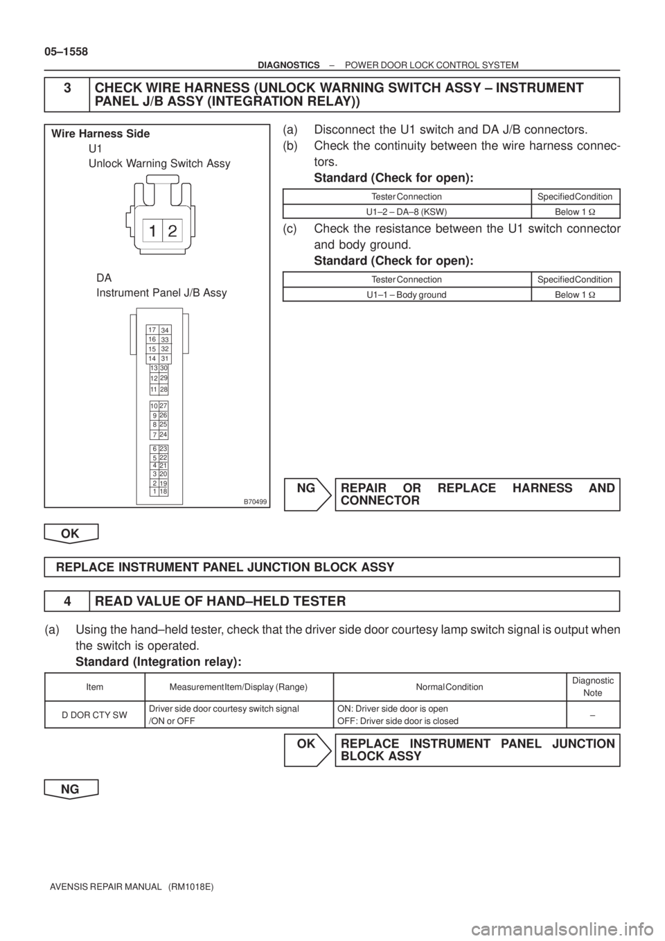
3 CHECK WIRE HARNESS (UNLOCK WARNING SWITCH ASSY ± INSTRUMENT
PANEL J/B ASSY (INTEGRATION RELAY))
(a) Disconnect the U1 switch and DA J/B connectors.
(b) Check the continuity between the wire harness connec-
tors.
Standard (Check for open):
Tester ConnectionSpecified Condition
U1±2 ± DA±8 (KSW)Below 1 �
(c) Check the resistance between the U1 switch connector
and body ground.
Standard (Check for open):
Tester ConnectionSpecified Condition
U1±1 ± Body groundBelow 1 �
NG REPAIR OR REPLACE HARNESS AND
CONNECTOR
OK
REPLACE INSTRUMENT PANEL JUNCTION BLOCK ASSY
4 READ VALUE OF HAND±HELD TESTER
(a) Using the hand±held tester, check that the driver side door courtesy lamp switch signal is output when
the switch is operated.
Standard (Integration relay):
ItemMeasurement Item/Display (Range)Normal ConditionDiagnostic
Note
D DOR CTY SWDriver side door courtesy switch signal
/ON or OFFON: Driver side door is open
OFF: Driver side door is closed±
OK REPLACE INSTRUMENT PANEL JUNCTION
BLOCK ASSY
NG
Page 1627 of 5135
05C8A±01
±
DIAGNOSTICS POWER DOOR LOCK CONTROL SYSTEM
05±1545
AVENSIS REPAIR MANUAL (RM1018E)
PROBLEM SYMPTOMS TABLE
SymptomSuspected AreaSee Page
All doors cannot be locked/unlocked at once
3. DOOR fuse
4. ECU±B 2 fuse
5. Power window regulator master switch assy
6. Front door lock assy LH, RH (Driver side)
7. Instrument panel J/B assy (Integration relay)
8. Wire harness
05±1546
Key lock±in prevention function does not work properly (Manual
operation and operation interlocked with key are active)
1. Unlock warning switch assy
2. Courtesy lamp switch assy LH, RH (Driver side)
3. Instrument panel J/B assy (Integration relay)
4. Wire harness
05±1555
w/ Double lock:
Double lock function does not operate properly
1. Wireless system
2. DOOR fuse
3. ECU±B 2 fuse
4. Front door lock assy LH, RH
5. Rear door lock assy LH, RH
6. Instrument panel J/B assy (Integration relay)
7. Wire harness
05±1560
Page 1637 of 5135
054CM±07
B65753
Transponder Key ECU Assy
ECM
Security Indicator
Transponder Key Amplifier
(Transponder Key Coil)
Unlock Warning Switch Assy
Transponder Key ECU Assy
Transponder Key Amplifier
(Transponder Key Coil)
Unlock Warning Switch Assy
ECM
Driver Side R/B Assy
Passenger Side R/B Assy
Center J/B
LHD Models
RHD Models 05±1606
± DIAGNOSTICSENGINE IMMOBILISER SYSTEM
AVENSIS REPAIR MANUAL (RM1018E)
LOCATION
Page 1638 of 5135

054CI±07
±
DIAGNOSTICS ENGINE IMMOBILISER SYSTEM
05±1605
AVENSIS REPAIR MANUAL (RM1018E)
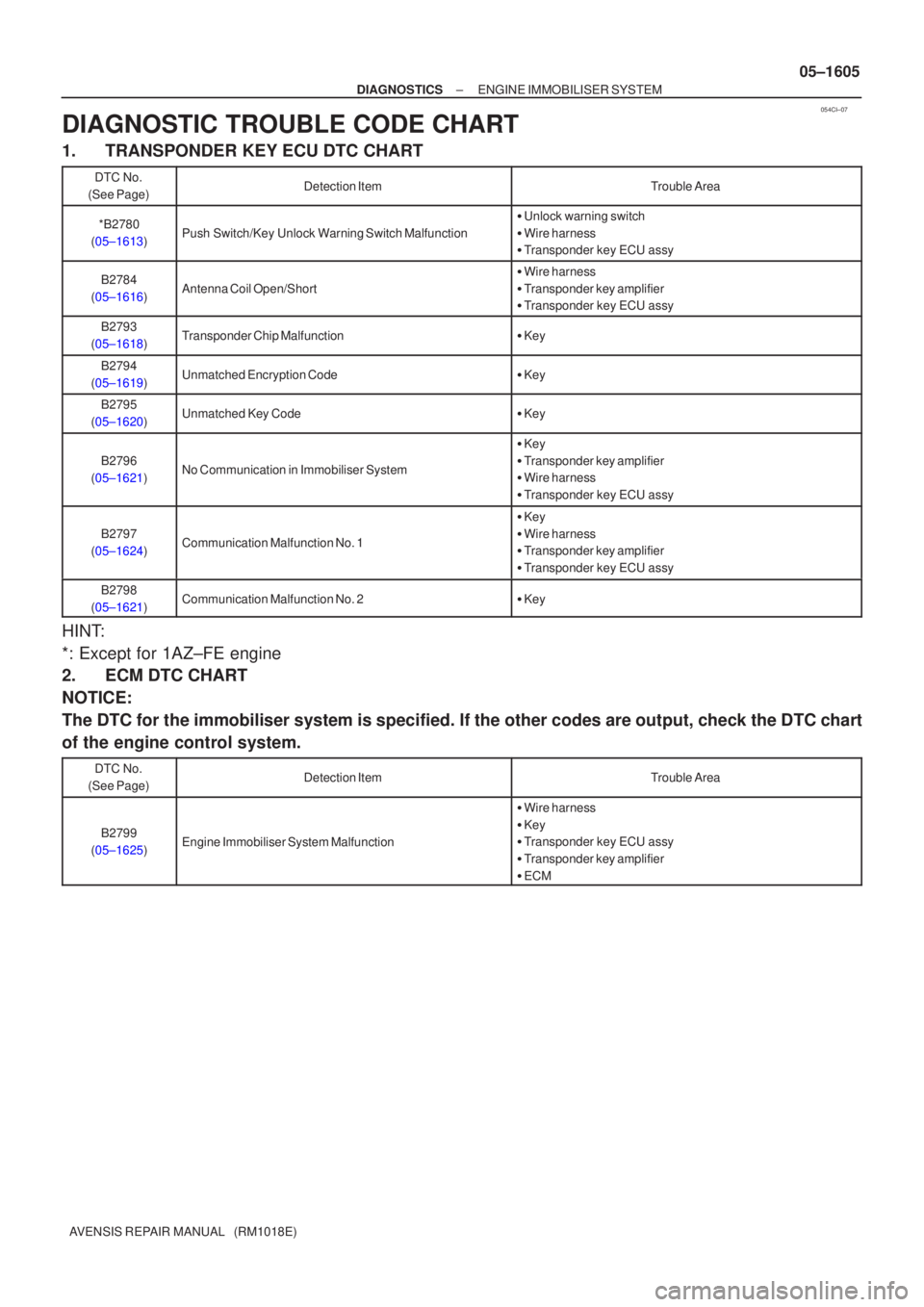
DIAGNOSTIC TROUBLE CODE CHART
1. TRANSPONDER KEY ECU DTC CHART
DTC No.
(See Page)Detection ItemTrouble Area
*B2780
(05±1613)Push Switch/Key Unlock Warning Switch Malfunction
� Unlock warning switch
� Wire harness
� Transponder key ECU assy
B2784
(05±1616)Antenna Coil Open/Short
� Wire harness
� Transponder key amplifier
� Transponder key ECU assy
B2793
(05±1618)Transponder Chip Malfunction� Key
B2794
(05±1619)Unmatched Encryption Code� Key
B2795
(05±1620)Unmatched Key Code� Key
B2796
(05±1621)No Communication in Immobiliser System
� Key
� Transponder key amplifier
� Wire harness
� Transponder key ECU assy
B2797
(05±1624)Communication Malfunction No. 1
� Key
� Wire harness
� Transponder key amplifier
� Transponder key ECU assy
B2798
(05±1621)Communication Malfunction No. 2� Key
HINT:
*: Except for 1AZ±FE engine
2. ECM DTC CHART
NOTICE:
The DTC for the immobiliser system is specified. If the other codes are out\
put, check the DTC chart
of the engine control system.
DTC No.
(See Page)Detection ItemTrouble Area
B2799
(05±1625)Engine Immobiliser System Malfunction
� Wire harness
� Key
� Transponder key ECU assy
� Transponder key amplifier
� ECM
Page 1640 of 5135

± DIAGNOSTICSENGINE IMMOBILISER SYSTEM
05±1603
AVENSIS REPAIR MANUAL (RM1018E)
3. CHECK DIAGNOSIS
(a) Using the hand±held tester, check for DTCs.
NOTICE:
Hand±held tester only:
When the diagnosis system is switched from normal mode to check mode, all the DTCs and freeze
frame data recorded in normal mode are erased. So before switching modes, always check the DTCs
and freeze frame data, and make a note of them.
(1) Prepare the hand±held tester.
(2) Connect the hand±held tester to the DLC3 under the instrument panel lower pad.
(3) Turn the ignition switch ON and push the hand±held tester switch ON.
(4) Use the hand±held tester to check for DTCs and freeze frame data, and make a note of them
(For operating instructions, see the hand±held tester instruction book).
(5) Confirm the details of the DTCs.
(b) Either of the following procedures will erase the DTCs and freeze frame data.
(1) Operating the hand±held tester to erase the codes (See the hand±held tester instruction book
for operating instructions).
(2) Disconnecting the battery terminals or ECU±B fuse.
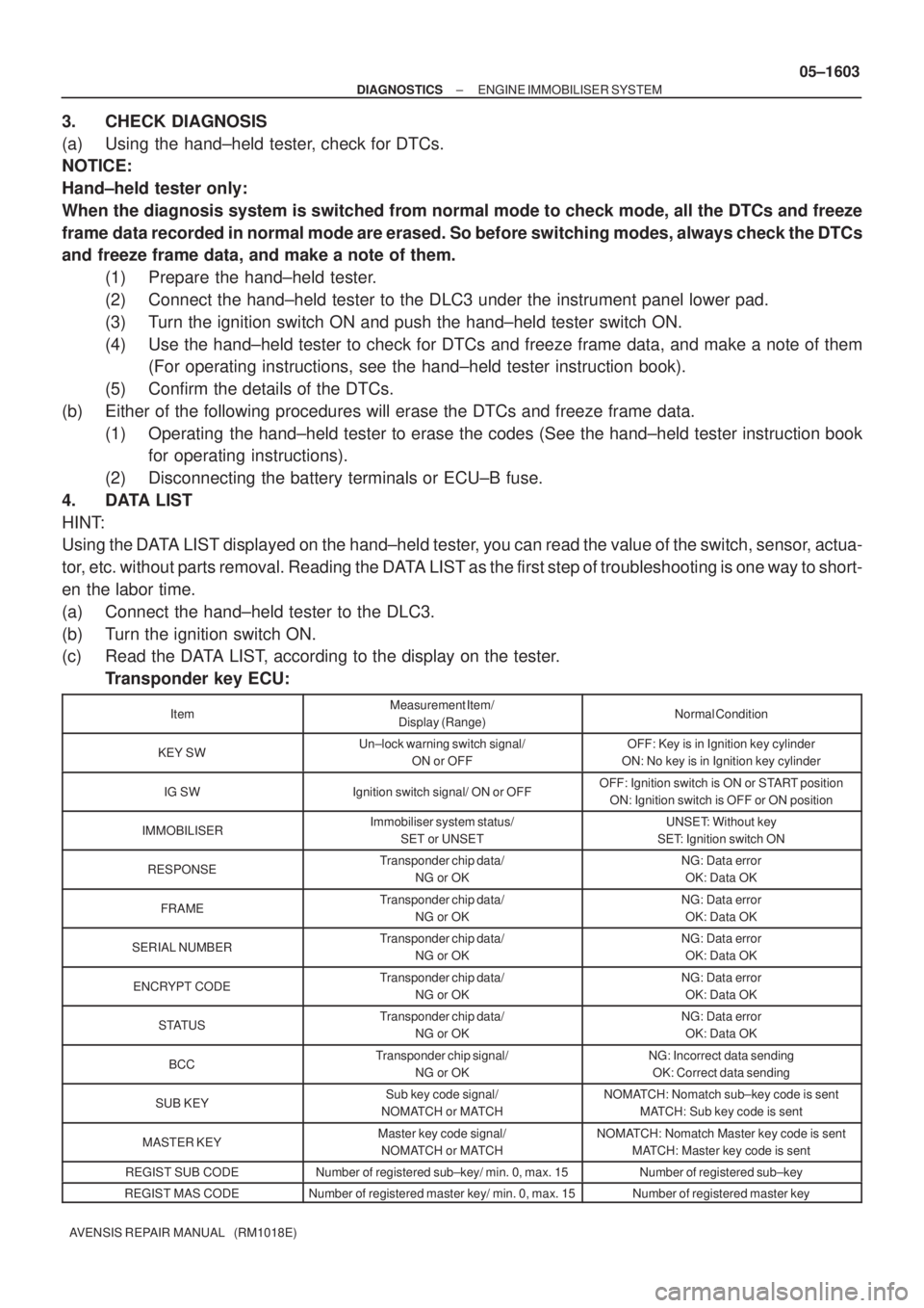
4. DATA LIST
HINT:
Using the DATA LIST displayed on the hand±held tester, you can read the value of the switch, sensor, actua-
tor, etc. without parts removal. Reading the DATA LIST as the first step of troubleshooting is one way to short-
en the labor time.
(a) Connect the hand±held tester to the DLC3.
(b) Turn the ignition switch ON.
(c) Read the DATA LIST, according to the display on the tester.
Transponder key ECU:
ItemMeasurement Item/
Display (Range)Normal Condition
KEY SWUn±lock warning switch signal/
ON or OFFOFF: Key is in Ignition key cylinder
ON: No key is in Ignition key cylinder
IG SWIgnition switch signal/ ON or OFFOFF: Ignition switch is ON or START position
ON: Ignition switch is OFF or ON position
IMMOBILISERImmobiliser system status/
SET or UNSETUNSET: Without key
SET: Ignition switch ON
RESPONSETransponder chip data/
NG or OKNG: Data error
OK: Data OK
FRAMETransponder chip data/
NG or OKNG: Data error
OK: Data OK
SERIAL NUMBERTransponder chip data/
NG or OKNG: Data error
OK: Data OK
ENCRYPT CODETransponder chip data/
NG or OKNG: Data error
OK: Data OK
STATUSTransponder chip data/
NG or OKNG: Data error
OK: Data OK
BCCTransponder chip signal/
NG or OKNG: Incorrect data sending
OK: Correct data sending
SUB KEYSub key code signal/
NOMATCH or MATCHNOMATCH: Nomatch sub±key code is sent
MATCH: Sub key code is sent
MASTER KEYMaster key code signal/
NOMATCH or MATCHNOMATCH: Nomatch Master key code is sent
MATCH: Master key code is sent
REGIST SUB CODENumber of registered sub±key/ min. 0, max. 15Number of registered sub±key
REGIST MAS CODENumber of registered master key/ min. 0, max. 15Number of registered master key