Page 1232 of 5135
± DIAGNOSTICSSUPPLEMENTAL RESTRAINT SYSTEM
05±1193
AVENSIS REPAIR MANUAL (RM1018E)
*1: RHD, *2: LHD, *3: w/ Curtain Shield Airbag
HINT:
�When the SRS warning light remains on and the DTC is the normal code, a voltage source drop is sus-
pected.
This malfunction is not stored in memory by the airbag sensor assy center and if the power source
voltage returns to normal, the SRS warning light will automatically go off.
�If a code not listed on the displayed chart, the airbag sensor assy center may be failed.
�In the case of any malfunction concerning any open circuit, short to ground, or short to B+ due to any
squib, another malfunction code may not be detected. In this case, repair the malfunction currently
indicated and then perform malfunction diagnosis again. Another malfunction code may then be de-
tected.
Page 1233 of 5135

05C5V±01
3
2
145678
910111213141516
DLC3
A04550
C93955
05±1184
±
DIAGNOSTICS SUPPLEMENTAL RESTRAINT SYSTEM
AVENSIS REPAIR MANUAL (RM1018E)
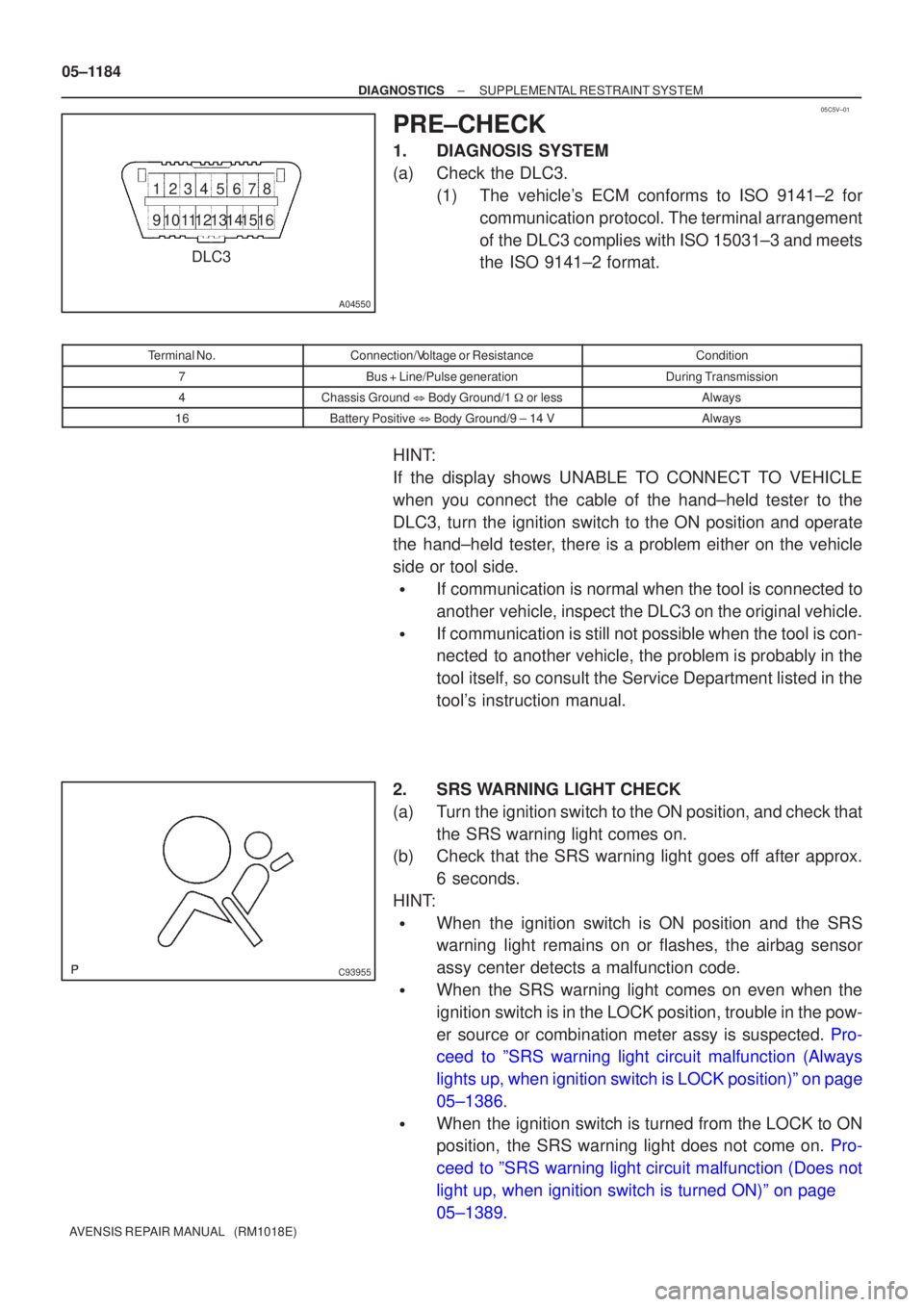
PRE±CHECK
1.DIAGNOSIS SYSTEM
(a)Check the DLC3. (1)The vehicle's ECM conforms to ISO 9141±2 forcommunication protocol. The terminal arrangement
of the DLC3 complies with ISO 15031±3 and meets
the ISO 9141±2 format.
Terminal No.Connection/Voltage or ResistanceCondition
7Bus + Line/Pulse generationDuring Transmission
4Chassis Ground � Body Ground/1 � or lessAlways
16Battery Positive � Body Ground/9 ± 14 VAlways
HINT:
If the display shows UNABLE TO CONNECT TO VEHICLE
when you connect the cable of the hand±held tester to the
DLC3, turn the ignition switch to the ON position and operate
the hand±held tester, there is a problem either on the vehicle
side or tool side.
�If communication is normal when the tool is connected to
another vehicle, inspect the DLC3 on the original vehicle.
�If communication is still not possible when the tool is con-
nected to another vehicle, the problem is probably in the
tool itself, so consult the Service Department listed in the
tool's instruction manual.
2.SRS WARNING LIGHT CHECK
(a)Turn the ignition switch to the ON position, and check that the SRS warning light comes on.
(b)Check that the SRS warning light goes off after approx.
6 seconds.
HINT:
�When the ignition switch is ON position and the SRS
warning light remains on or flashes, the airbag sensor
assy center detects a malfunction code.
�When the SRS warning light comes on even when the
ignition switch is in the LOCK position, trouble in the pow-
er source or combination meter assy is suspected. Pro-
ceed to ºSRS warning light circuit malfunction (Always
lights up, when ignition switch is LOCK position)º on page
05±1386.
�When the ignition switch is turned from the LOCK to ON
position, the SRS warning light does not come on. Pro-
ceed to ºSRS warning light circuit malfunction (Does not
light up, when ignition switch is turned ON)º on page
05±1389.
Page 1235 of 5135

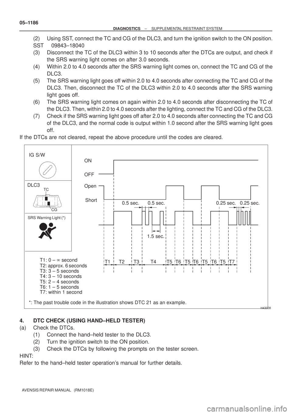
H43008
IG S/W
DLC3
SRS Warning Light (*)
ON
OFF
Open
Short
0.5 sec.
1.5 sec.
T1
0.25 sec.
T2 T3 T4 T5 T6 T5 T6 T5 T6 T5 T70.5 sec.0.25 sec.
CG TC
T1: 0 ± � second
T2: approx. 6 seconds
T3: 3 ± 5 seconds
T7: within 1 second
*: The past trouble code in the illustration shows DTC 21 as an example.T4: 3 ± 10 seconds
T5: 2 ± 4 seconds
T6: 1 ± 5 seconds 05±1186
± DIAGNOSTICSSUPPLEMENTAL RESTRAINT SYSTEM
AVENSIS REPAIR MANUAL (RM1018E)
(2) Using SST, connect the TC and CG of the DLC3, and turn the ignition switch to the ON position.
SST 09843±18040
(3) Disconnect the TC of the DLC3 within 3 to 10 seconds after the DTCs are output, and check if
the SRS warning light comes on after 3.0 seconds.
(4) Within 2.0 to 4.0 seconds after the SRS warning light comes on, connect the TC and CG of the
DLC3.
(5) The SRS warning light goes off within 2.0 to 4.0 seconds after connecting the TC and CG of the
DLC3. Then, disconnect the TC of the DLC3 within 2.0 to 4.0 seconds after the SRS warning
light goes off.
(6) The SRS warning light comes on again within 2.0 to 4.0 seconds after disconnecting the TC of
the DLC3. Then, within 2.0 to 4.0 seconds after the lighting, connect the TC and CG of the DLC3.
(7) Check if the SRS warning light goes off after 2.0 to 4.0 seconds after connecting the TC and CG
of the DLC3, and the normal code is output within 1.0 second after the SRS warning light goes
off.
If the DTCs are not cleared, repeat the above procedure until the codes are cleared.
4. DTC CHECK (USING HAND±HELD TESTER)
(a) Check the DTCs.
(1) Connect the hand±held tester to the DLC3.
(2) Turn the ignition switch to the ON position.
(3) Check the DTCs by following the prompts on the tester screen.
HINT:
Refer to the hand±held tester operation's manual for further details.
Page 1239 of 5135
050WX±16
[
]
[]
[]
H40122
Supplemental Restraint System Check SheetInspector 's
Name
Date Vehicle Brought InVIN
Production Date
Licence No.
Odometer Readingkm
Miles
Date Problem Occurred
Weather
TemperatureFine Cloudy Rainy Snowy Other
Approx.
Starting Idling
Driving Constant speed Acceleration Deceleration
Other Vehicle Operation
Road Condition
Details of Problem
Vehicle Inspection, Repair Histo-
ry Prior to Occurrence of Mal-
function (Including Supplemen-
tal Restraint System)
Diagnosis System Inspection
SRS Warning Light
Inspection
DTC Inspection1st Time
2nd TimeRemains ON Does Not Come on
Normal Code Malfunction Code Code. Customer 's Name
1st Time
2nd TimeSometimes Comes on
Remains ON Does Not Come onSometimes Comes on
Normal Code Malfunction Code Code.
± DIAGNOSTICSSUPPLEMENTAL RESTRAINT SYSTEM
05±1183
AVENSIS REPAIR MANUAL (RM1018E)
CUSTOMER PROBLEM ANALYSIS CHECK
Page 1241 of 5135
05±1182
±
DIAGNOSTICS SUPPLEMENTAL RESTRAINT SYSTEM
AVENSIS REPAIR MANUAL (RM1018E)
10SYMPTOM SIMULATION (See page 01±22)
WARNING LIGHT REMAINS OFF: Go to step 11
WARNING LIGHT IS ON: Go to step 4
11 CONFIRMATION TEST
END
Page 1432 of 5135
H43588
Driver Side J/BAirbag Sensor Assy Center
D5 DLC3
TCW−
L
J21D
J/C
(*2) TC
(*2)
W− L
(*1) J20
B
(*2)
J8
B
(*1) W−
L
DB17
DD8
J8 B
(*1) A27
19
13 W−
L
1AZ−
FSE, 1CD− FTV Engine:
CG TC TC
TC
TC
W−
L
W− L
W− L
W−
L
W−B
W−
B
W−
B
W− B
(*1)
(*2) J9 J21
DD
(*2)(*1)
DL DC
15
3
E9
S1
S2
20
17
25
(*2)
A
J16
J/C
A
(*1)
IO IP
(*3)
M1
16
4
CA
CB 3
6
(*6)
(*4, *5)
Skid Control ECU with Actuator Skid Control ECU with Actuator ECM
Multi− Display
*1: LHD *2: RHD
*3: w/ Navigation System (Map Type) *4:
1AZ− FSE
*5: 1CD− FTV (w/ VSC)
*6: 1CD− FTV (w/ ABS)
Center J/B
−
DIAGNOSTICS SUPPLEMENTAL RESTRAINT SYSTEM
05−1391
TC TERMINAL CIRCUIT
CIRCUIT DESCRIPTION
DTC output mode is set by connecting terminals TC and CG of the DLC3.
The DTCs are displayed by blinking the SRS warning light.
WIRING DIAGRAM
05C65 −01
Page 1434 of 5135
H43589
Driver Side J/BAirbag Sensor Assy Center
D5 DLC3
TCW−
L
J8 TC
(*2)
(*1)
W−L
DB 17
DD8
B
(*1) A27
19
*1: LHD B
13
1ZZ−
FE, 3ZZ −FE Engine:
W−L
W−
L
W−L
J8
J9 D
TCTC
TC
CG
W−
B
W− B
W−B W−
B
M116
4
AJ16
J/C
A
IO IP
(*2)
(*1) (*2)
(*1) CA
CB 6
3 J/C
DC
DL 3
15
E920
S2 25 ECM
Skid Control ECU with Actuator Multi−Display
*2: RHD
*3: w/ Navigation System (Map Type) B
B
J20 J20
(*1)
J9D
D
D
J21 J21
(*2)
TC
W−
L
W−
B(*1)
E15 4
W−L(*1) Center J/B
(*2) (*1)(*
1) (*2)
(*3)
W−
L
(*2) W−
L
(*2)
EPS ECU
−
DIAGNOSTICS SUPPLEMENTAL RESTRAINT SYSTEM
05−1392-1
HINT:
When each warning light stays blinking, a ground short in the wiring of terminal TC of the DLC3 or an internal
ground short in each ECU is suspected.
Page 1437 of 5135

± DIAGNOSTICSSUPPLEMENTAL RESTRAINT SYSTEM
05±1389
AVENSIS REPAIR MANUAL (RM1018E)
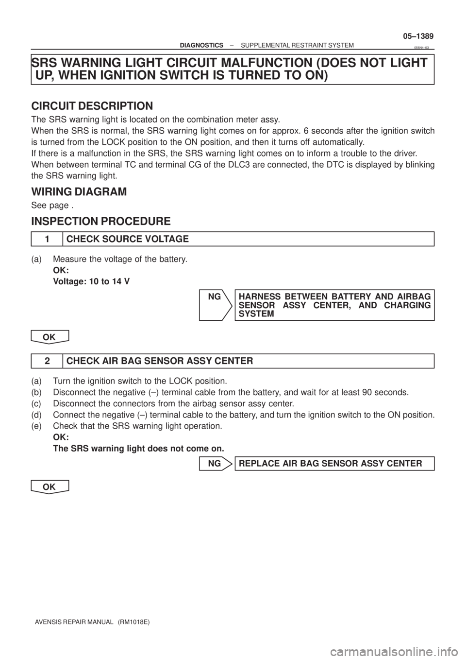
SRS WARNING LIGHT CIRCUIT MALFUNCTION (DOES NOT LIGHT
UP, WHEN IGNITION SWITCH IS TURNED TO ON)
CIRCUIT DESCRIPTION
The SRS warning light is located on the combination meter assy.
When the SRS is normal, the SRS warning light comes on for approx. 6 seconds after the ignition switch
is turned from the LOCK position to the ON position, and then it turns off automatically.
If there is a malfunction in the SRS, the SRS warning light comes on to inform a trouble to the driver.
When between terminal TC and terminal CG of the DLC3 are connected, the DTC is displayed by blinking
the SRS warning light.
WIRING DIAGRAM
See page .
INSPECTION PROCEDURE
1 CHECK SOURCE VOLTAGE
(a) Measure the voltage of the battery.
OK:
Voltage: 10 to 14 V
NG HARNESS BETWEEN BATTERY AND AIRBAG
SENSOR ASSY CENTER, AND CHARGING
SYSTEM
OK
2 CHECK AIR BAG SENSOR ASSY CENTER
(a) Turn the ignition switch to the LOCK position.
(b) Disconnect the negative (±) terminal cable from the battery, and wait for at least 90 seconds.
(c) Disconnect the connectors from the airbag sensor assy center.
(d) Connect the negative (±) terminal cable to the battery, and turn the ignition switch to the ON position.
(e) Check that the SRS warning light operation.
OK:
The SRS warning light does not come on.
NG REPLACE AIR BAG SENSOR ASSY CENTER
OK
056N4±03