Page 1439 of 5135
H42518
Combination Meter Assy
Driver Side J/BAirbag Sensor Assy Center
*1: LHD
*2: RHD
*3: Gasoline
*4: 1CD±FTV SRS8
C11B±Y
J16
J/C(*2)
IL 17
C1012
DA6
DDB±Y3
A27
LA
W±B
J15
J/C W±B
(*1)
A
AW±B
W±B
(*1, *4)(*1, *3)(*2) W±B
A
A J17
J/C
A
IO
IK 05±1386
± DIAGNOSTICSSUPPLEMENTAL RESTRAINT SYSTEM
AVENSIS REPAIR MANUAL (RM1018E)
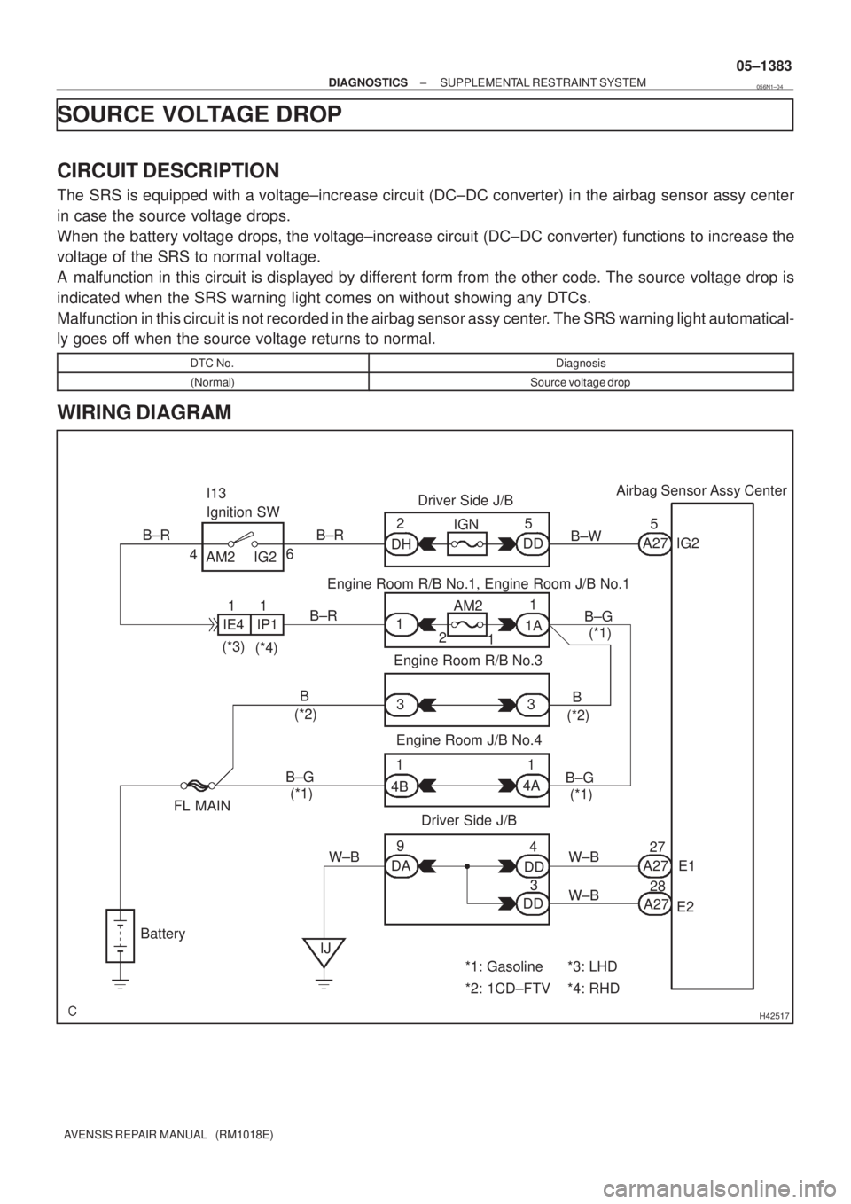
SRS WARNING LIGHT CIRCUIT MALFUNCTION (ALWAYS LIGHT
UP, WHEN IGNITION SWITCH IS ACC OR LOCK POSITION)
CIRCUIT DESCRIPTION
The SRS warning light is located on the combination meter assy.
When the SRS is normal, the SRS warning light comes on for approx. 6 seconds after the ignition switch
is turned from the LOCK position to the ON position, and then it turns off automatically.
If there is a malfunction in the SRS, the SRS warning light comes on to inform a trouble to the driver.
When between terminal TC and terminal CG of the DLC3 are connected, the DTC is displayed by blinking
the SRS warning light.
WIRING DIAGRAM
05C64±01
Page 1442 of 5135

H42517
Airbag Sensor Assy Center
A275
E1
E2 27IG2 2
1
Battery28 4IGN Driver Side J/B
IG2
AM2 I13
Ignition SW
B
4 3 6
Engine Room R/B No.1, Engine Room J/B No.1 AM2B±R
DD
W±BB±W
A27
A27 DD DH5
DAW±B 1 11
B±R1
1
1A
2
1 IE4 IP1
(*3)
(*4)(*1) B±G
Engine Room R/B No.3
Engine Room J/B No.43
DD 4B4A
3 9(*1) B±G (*2)
(*1) B±GB
(*2)
Driver Side J/B
IJ FL MAIN
W±B
*1: Gasoline
*2: 1CD±FTV*3: LHD
*4: RHD B±R
± DIAGNOSTICSSUPPLEMENTAL RESTRAINT SYSTEM
05±1383
AVENSIS REPAIR MANUAL (RM1018E)
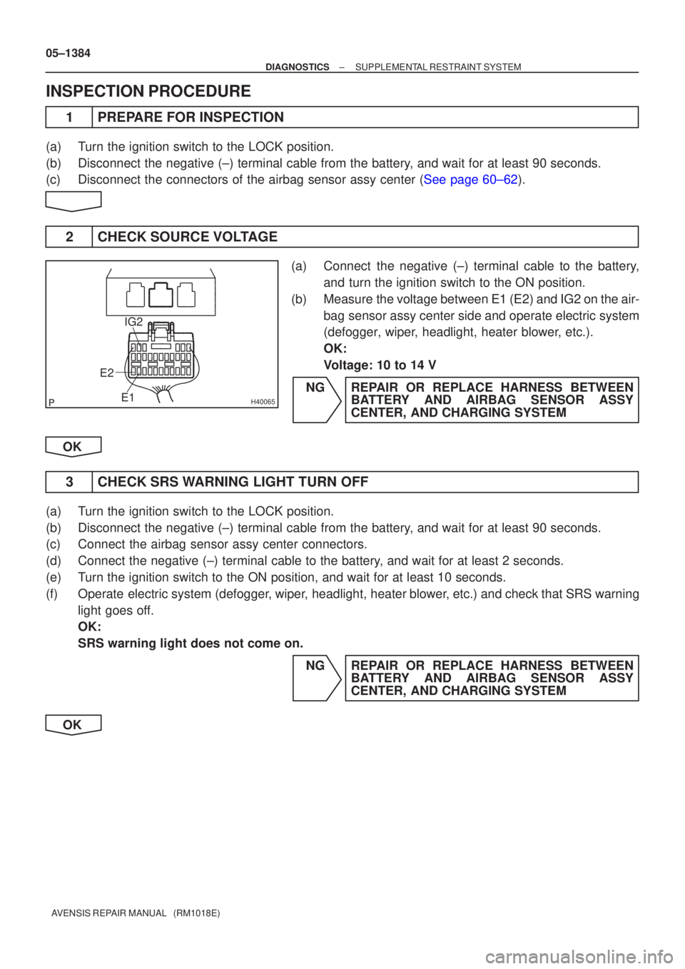
SOURCE VOLTAGE DROP
CIRCUIT DESCRIPTION
The SRS is equipped with a voltage±increase circuit (DC±DC converter) in the airbag sensor assy center
in case the source voltage drops.
When the battery voltage drops, the voltage±increase circuit (DC±DC converter) functions to increase the
voltage of the SRS to normal voltage.
A malfunction in this circuit is displayed by different form from the other code. The source voltage drop is
indicated when the SRS warning light comes on without showing any DTCs.
Malfunction in this circuit is not recorded in the airbag sensor assy center. The SRS warning light automatical-
ly goes off when the source voltage returns to normal.
DTC No.Diagnosis
(Normal)Source voltage drop
WIRING DIAGRAM
056N1±04
Page 1443 of 5135

H40065
IG2
E2 E1
05±1384
±
DIAGNOSTICS SUPPLEMENTAL RESTRAINT SYSTEM
AVENSIS REPAIR MANUAL (RM1018E)
INSPECTION PROCEDURE
1PREPARE FOR INSPECTION
(a)Turn the ignition switch to the LOCK position.
(b)Disconnect the negative (±) terminal cable from the battery, and wait for at least 90 seconds.
(c)Disconnect the connectors of the airbag sensor assy center (See page 60±62).
2 CHECK SOURCE VOLTAGE
(a) Connect the negative (±) terminal cable to the battery, and turn the ignition switch to the ON position.
(b) Measure the voltage between E1 (E2) and IG2 on the air- bag sensor assy center side and operate electric system
(defogger, wiper, headlight, heater blower, etc.).
OK:
Voltage: 10 to 14 V
NG REPAIR OR REPLACE HARNESS BETWEEN BATTERY AND AIRBAG SENSOR ASSY
CENTER, AND CHARGING SYSTEM
OK
3 CHECK SRS WARNING LIGHT TURN OFF
(a) Turn the ignition switch to the LOCK position.
(b) Disconnect the negative (±) terminal cable from the battery, and wait for at least 90 seconds.
(c) Connect the airbag sensor assy center connectors.
(d) Connect the negative (±) terminal cable to the battery, and wait for at least 2 seconds.
(e) Turn the ignition switch to the ON position, and wait for at least 10 sec\
onds.
(f) Operate electric system (defogger, wiper, headlight, heater blower, etc.) and check that SRS warning light goes off.
OK:
SRS warning light does not come on.
NG REPAIR OR REPLACE HARNESS BETWEENBATTERY AND AIRBAG SENSOR ASSY
CENTER, AND CHARGING SYSTEM
OK
Page 1526 of 5135
056QC±04
±
DIAGNOSTICS COMBINATION METER
05±1509
AVENSIS REPAIR MANUAL (RM1018E)
PROBLEM SYMPTOMS TABLE
Chart No.SymptomSee page
1Malfunction in speedometer05±1510
2Malfunction in tachometer05±1513
3Malfunction in water temperature receiver gauge05±1515
4Malfunction in fuel receiver gauge05±1517
5Entire combination meter does not operate05±1519
6Seat belt warning lamp for driver's seat does not operate05±1522
7Seat belt warning lamp for front passenger's seat does not flash05±1524
8The ambient temperature does not display05±1527
9Warning buzzer does not sound05±1530
Page 1527 of 5135

05C4G±01
I35933
C10 C11
05±1506
± DIAGNOSTICSCOMBINATION METER
AVENSIS REPAIR MANUAL (RM1018E)
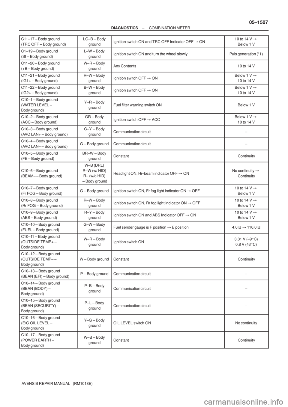
TERMINALS OF ECU
COMBINATION METER ASSY
Terminal No.Wiring colorConditionSpecified condition
C11±1 ± Body ground
(TURN L ± Body ground)G±W ± Body
groundTurn signal LH indicator light OFF � ONBelow 1 V �
10 to 14 V
C11±2 ± Body ground
(BRAKE LVL SW ±
Body ground)R±W ± Body
groundBrake fluid level warning switch ONBelow 1 V
C11±3 ± Body ground
(TACHO ± Body ground)GR±R ± Body
groundIgnition switch OFF � ON, Engine idle speedPuls generation (*2)
C11±5 ± Body ground
(SIGNAL EARTH ±
Body ground)W±B ± Body
groundConstantContinuity
C11±6 ± Body ground
(EMPS ± Body ground)B±W ± Body
groundIgnition switch ON and EMPS Indicator OFF � ON10 to 14 V �
Below 1 V
C11±8 ± Body ground
(AIRBAG ± Body ground)B±Y ± Body
groundIgnition switch ON and AIRBAG Indicator OFF � ON10 to 14 V �
Below 1 V
C11±9 ± Body ground
(CHECK ENGINE ±
Body ground)
W ± Body groundEngine running and CHECK ENGINE indicator OFF9 to 14 V
C11±10 ± Body ground
(AUTO LEVELING ±
Body ground)LG ± Body
groundIgnition switch ON and AUTO LEVERING Indicator OFF � ON10 to 14 V �
Below 1 V
C11±11 ± Body ground
(OIL PRESS SW ±
Body ground)Y±B ± Body
groundEngine running�StoppedNo continuity �
Continuity
C11±12 ± Body ground
(BEAM+ ± Body ground)R±W (w/HID),
R (w/o HID) ±
Body ground
Headlight OFF�ONBelow 1 V �
10 to 14 V
C11±13 ± Body ground
(TURN R ± Body ground)G±Y ± Body
groundTurn signal RH indicator light OFF � ONBelow 1 V �
10 to 14 V
C11±14 ± Body ground
(ILL+ ± Body ground)G ± Body groundCombination switch OFF�ONBelow 1 V �
10 to 14 V
C11±15 ± Body ground
(SLIP ± Body ground)LG ± Body
groundIgnition switch ON and SLIP Indicator OFF � ON10 to 14 V �
Below 1 V
C11±16 ± Body ground
(VSC ± Body ground)W±R ± Body
groundIgnition switch ON and VSC Indicator OFF � ON10 to 14 V �
Below 1 V
Page 1528 of 5135

± DIAGNOSTICSCOMBINATION METER
05±1507
AVENSIS REPAIR MANUAL (RM1018E) C11±17 ± Body ground
(TRC OFF ± Body ground)
LG±B ± Body
groundIgnition switch ON and TRC OFF Indicator OFF � ON10 to 14 V �
Below 1 V
C1±19 ± Body ground
(SI ± Body ground)L±W ± Body
groundIgnition switch ON and turn the wheel slowlyPuls generation (*1)
C11±20 ± Body ground
(+B ± Body ground)W±R ± Body
groundAny Contents10 to 14 V
C11±21 ± Body ground
(IG1+ ± Body ground)R±W ± Body
groundIgnition switch OFF � ONBelow 1 V �
10 to 14 V
C11±22 ± Body ground
(IG2+ ± Body ground)B±W ± Body
groundIgnition switch OFF � ONBelow 1 V �
10 to 14 V
C10±1 ± Body ground
(WATER LEVEL ±
Body ground)Y±R ± Body
groundFuel filter warning switch ONBelow 1 V
C10±2 ± Body ground
(ACC ± Body ground)GR ± Body
groundIgnition switch OFF � ACCBelow 1 V �
10 to 14 V
C10±3 ± Body ground
(AVC LAN+ ± Body ground)G±Y ± Body
groundCommunication circuit±
C10±4 ± Body ground
(AVC LAN± ± Body ground)G ± Body groundCommunication circuit±
C10±5 ± Body ground
(FE ± Body ground)BR±W ± Body
groundConstantContinuity
C10±6 ± Body ground
(BEAM± ± Body ground)
W±B (DRL)
R±W (w/ HID)
R± (w/o HID)
± Body ground
Headlight ON, Hi±beam indicator OFF � ONNo continuity �
Continuity
C10±7 ± Body ground
(Fr FOG ± Body ground)G ± Body groundIgnition switch ON, Fr fog light indicator ON � OFF10 to 14 V �
Below 1 V
C10±8 ± Body ground
(Rr FOG ± Body ground)R±W ± Body
groundIgnition switch ON, Rr fog light indicator ON � OFF10 to 14 V �
Below 1 V
C10±9 ± Body ground
(ABS ± Body ground)R±Y ± Body
groundIgnition switch ON and ABS Indicator OFF � ON10 to 14 V �
Below 1 V
C10±10 ± Body ground
(FUEL ± Body ground)G±W ± Body
groundFuel sender gauge is F position � E position4.0 � � 110.0 �
C10±11 ± Body ground
(OUTSIDE TEMP+ ±
Body ground)W±R ± Body
groundIgnition switch ON3.31 V (±9�C)
0.8 V (43�C)
C10±12 ± Body ground
(OUTSIDE TEMP± ±
Body ground)
W ± Body groundConstantContinuity
C10±13 ± Body ground
(BEAN (EFI) ± Body ground)P ± Body groundCommunication circuit±
C10±14 ± Body ground
(BEAN (BODY) ±
Body ground)P±B ± Body
groundCommunication circuit±
C10±15 ± Body ground
(BEAN (SECURITY) ±
Body ground)P±L ± Body
groundCommunication circuit±
C10±16 ± Body ground
(E/G OIL LEVEL ±
Body ground)Y±G ± Body
groundOIL LEVEL switch ONNo continuity
C10±17 ± Body ground
(POWER EARTH ±
Body ground)W±B ± Body
groundConstantContinuity
Page 1531 of 5135
I34624
Front Seat Inner
Belt Assy LH
Occupant Detection Sensor
Front Seat Inner
Belt Assy RH
Passenger's Seat belt
Warning LampDriver Side R/BAccessary Meter
Combination Meter Assy
Driver Side J/B
Fuse Block
Center J/B
± DIAGNOSTICSCOMBINATION METER
05±1501
AVENSIS REPAIR MANUAL (RM1018E)
Page 1535 of 5135
Terminal No.
Wire harness side
Turn Signal Flasher Relay
Skid Control ECU with Actuator Brake Fluid Level Warning Switch
Engine ECU
Oil Pressure Switch
DOME Fuse Headlight Beam Level Control ECU
Skid Control ECU with Actuator
Skid Control ECU with Actuator Turn Signal Flasher Relay Engine ECU ± Multi Display RAD No.1 Fuse
GND
EMPS ECU
TAIL Fuse
Skid Control ECU with Actuator Fuel Sensor Gauge
Skid Control ECU with Actuator
± GND
Rear Fog Light Relay Front Fog Light Relay Multi Display Fuse Filter Warning Switch (*1)
IGN Fuse Fuel Sender Gauge
Engine Oil Level Sensor Security ECU Ambient Temp. Sensor
4P OUT (Other Parts) H±HI RH Fuse/H±LP RH Fuse 1
2
3
4
5
6
7
8
9
10
11
12
13
14
15
16
17
18
19
201
2
3
4
5
6
7
8
9
10
11
12
13
14
15
16
17
18
C10
Airbag Sensor Assembly GND
GAUGE1 Fuse Skid Control ECU with Actuator
C11Engine ECU
Integration Relay
21
22
*1: 1CD±FTVAmbient Temp. Sensor
± DIAGNOSTICSCOMBINATION METER
05±1505
AVENSIS REPAIR MANUAL (RM1018E)