Page 939 of 5135
F45145
*1: 1AZ±FSE
*2: 1CD±FTV*3: LHD
*4: RHD B±G
12 Engine Room J/B No.4
(*1)
(*2)
B1
4B1
4D ALT
FL MAIN
Engine Room R/B No.3
ALT
33
12(*2)
W B±G(*1) B±G(*1)(*2)
W
B±L(*2)1
ED1 Driver Side J/B
18
DBECU±IGIG1 Relay
1
DNBZ 15
S1 B±Y B±Y3
IE1Skid Control ECU
With Actuator V7
VSC Warning Buzzer
GC
J10 J20
(*4)J/C
(*3)G
C
J11 J21
(*4) (*3)R±W R±W
BatteryBuzzer
21 05±850
± DIAGNOSTICSABS WITH EBD & BA & TRC & VSC SYSTEM
AVENSIS REPAIR MANUAL (RM1018E)
SKID CONTROL BUZZER CIRCUIT
CIRCUIT DESCRIPTION
The skid control buzzer sounds during VSC operation.
WIRING DIAGRAM
0543K±04
Page 941 of 5135
)
AVENSIS REPAIR MANUAL (RM1018E)
PRE±CHECK
1.DIAGNOSIS SYSTEM
(a)Description (1)When troubleshooting TOYOTA AVENSIS 2005 Service Repair Manual 05C94±02
05±920±
DIAGNOSTICS ELECTRONIC CONTROLLED AUTOMATIC
TRANSAXLE [ECT](U241E(1AZ±FSE))
AVENSIS REPAIR MANUAL (RM1018E)
PRE±CHECK
1.DIAGNOSIS SYSTEM
(a)Description (1)When troubleshooting](/manual-img/14/57441/w960_57441-940.png)
05C94±02
05±920±
DIAGNOSTICS ELECTRONIC CONTROLLED AUTOMATIC
TRANSAXLE [ECT](U241E(1AZ±FSE))
AVENSIS REPAIR MANUAL (RM1018E)
PRE±CHECK
1.DIAGNOSIS SYSTEM
(a)Description (1)When troubleshooting Euro±OBD vehicles, theonly difference from the usual troubleshooting pro-
cedure is that you connect the vehicle to the OBD
scan tool complying with ISO 15031±4 or hand±
held tester, and read off various data output from
the vehicle's ECM.
(2)Euro±OBD regulations require that the vehicle's on±board computer illuminates the Check Engine
Warning Light (Malfunction Indicator Lamp)/CHK
ENG (MIL) on the instrument panel when the com-
puter detects a malfunction in the emission control
system/components or in the driving system com-
ponents which affect vehicle emissions, or a mal-
function in the computer. In addition to CHK ENG
(MIL) illuminating when a malfunction is detected,
the applicable Diagnostic Trouble Codes (DTCs)
prescribed by ISO15031±6 are recorded in the
ECM memory.
If the malfunction does not occur in 3±trip, the CHK ENG (MIL)
goes off but the DTCs remain recorded in the ECM memory. (3)To check the DTCs, connect the OBD scan tool orhand±held tester to the Data Link Connector 3
(DLC3) on the vehicle. The OBD scan tool or hand±
held tester also enables you to erase the DTCs and
check freezed frame data and various forms of en-
gine data (For operating instructions, see the OBD
scan tool's instruction book.).
(4)DTCs include ISO controlled codes and manufac- turer controlled codes. ISO controlled codes must
be set as prescribed by the ISO, while manufacturer
controlled codes can be set freely by the manufac-
turer within the prescribed limits (See DTC chart on
page 05±931).
(5) The diagnosis system operates in normal mode during normal vehicle use. It also has a check mode
for technicians to simulate malfunction symptoms
and troubleshoot. Most DTCs use 2 trip detection
logic (*) to prevent erroneous detection, and ensure
thorough malfunction detection. By switching the
ECM to check mode when troubleshooting, techni-
cians can cause the CHK ENG (MIL) to illuminate
for a malfunction that is only detected once or mo-
mentarily (Hand±held tester only) (See step 2).
Page 1084 of 5135
050WP±04
05±1058
±
DIAGNOSTICS ELECTRONIC MOTOR POWER STEERING SYSTEM
AVENSIS REPAIR MANUAL (RM1018E)
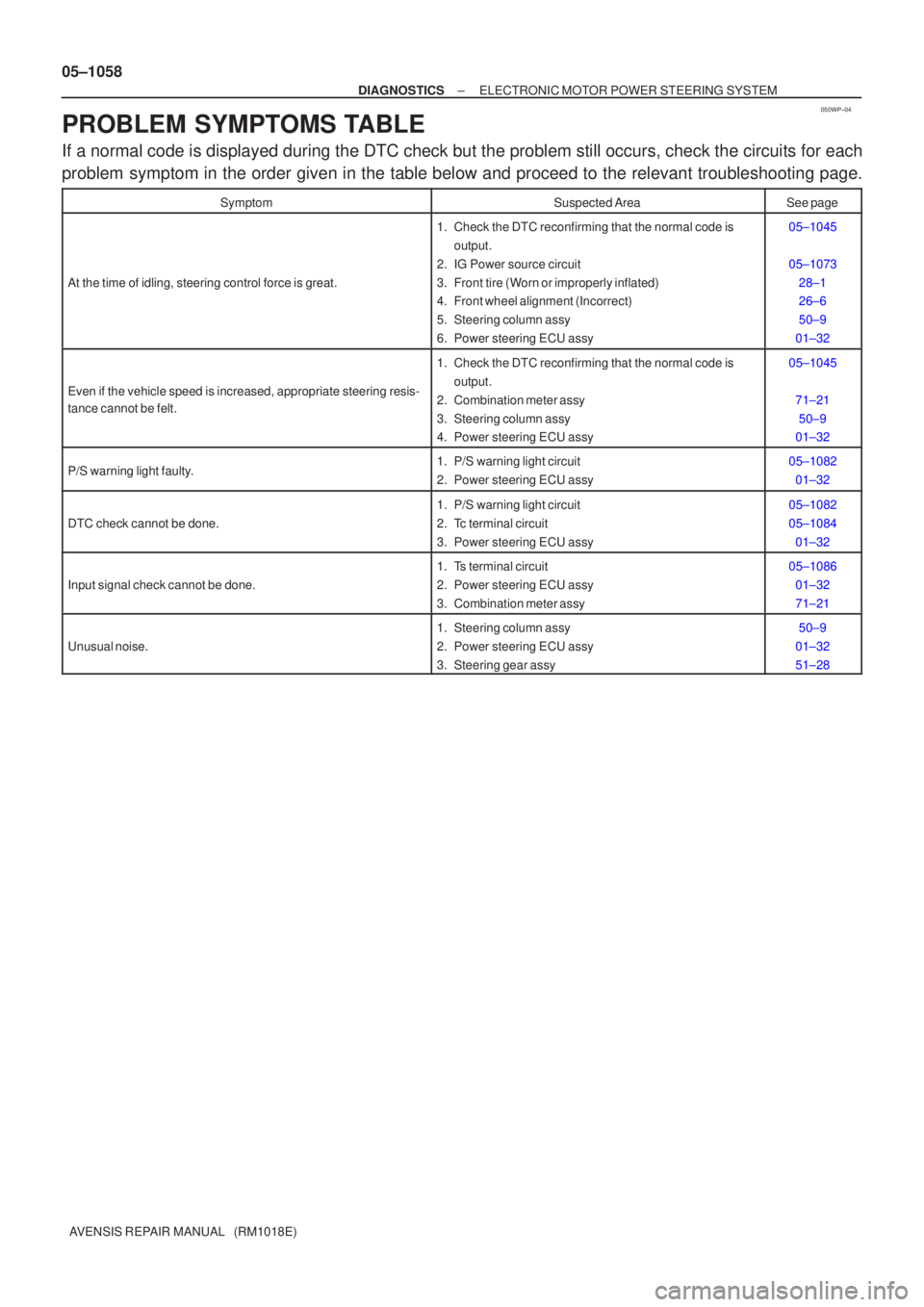
PROBLEM SYMPTOMS TABLE
If a normal code is displayed during the DTC check but the problem still o\
ccurs, check the circuits for each
problem symptom in the order given in the table below and proceed to the releva\
nt troubleshooting page.
SymptomSuspected AreaSee page
At the time of idling, steering control force is great.
1. Check the DTC reconfirming that the normal code is output.
2. IG Power source circuit
3. Front tire (Worn or improperly inflated)
4. Front wheel alignment (Incorrect)
5. Steering column assy
6. Power steering ECU assy05±1045
05±1073 28±1
26±6
50±9
01±32
Even if the vehicle speed is increased, appropriate steering resis-
tance cannot be felt.
1. Check the DTC reconfirming that the normal code is output.
2. Combination meter assy
3. Steering column assy
4. Power steering ECU assy05±1045
71±2150±9
01±32
P/S warning light faulty.1. P/S warning light circuit
2. Power steering ECU assy05±1082
01±32
DTC check cannot be done.
1. P/S warning light circuit
2. Tc terminal circuit
3. Power steering ECU assy05±1082
05±108401±32
Input signal check cannot be done.
1. Ts terminal circuit
2. Power steering ECU assy
3. Combination meter assy05±108601±32
71±21
Unusual noise.
1. Steering column assy
2. Power steering ECU assy
3. Steering gear assy50±9
01±32
51±28
Page 1085 of 5135
050WO±04
F44303
E14
Connector AE15
Connector B
± DIAGNOSTICSELECTRONIC MOTOR POWER STEERING SYSTEM
05±1057
AVENSIS REPAIR MANUAL (RM1018E)
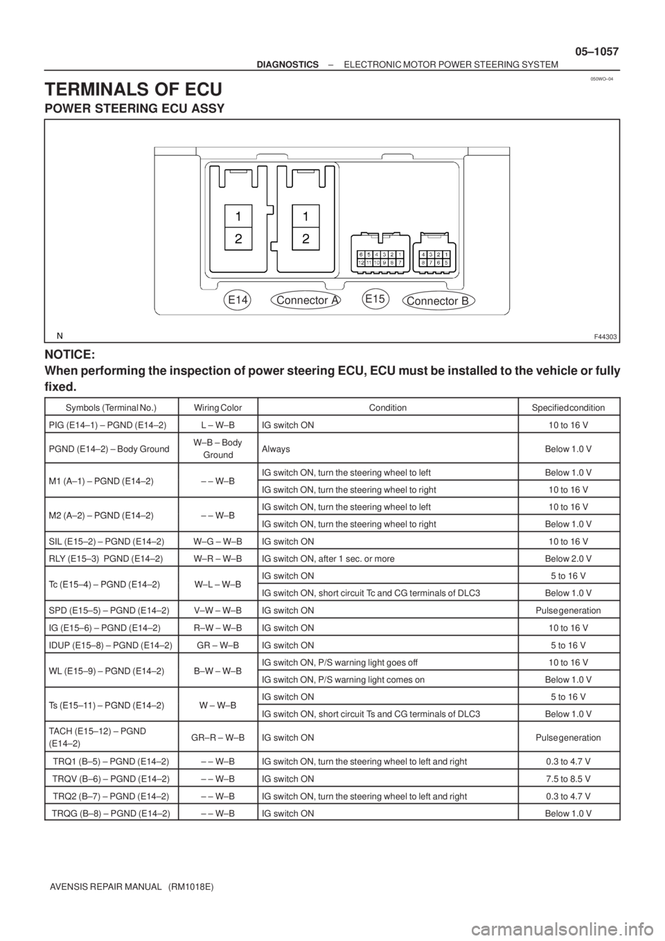
TERMINALS OF ECU
POWER STEERING ECU ASSY
NOTICE:
When performing the inspection of power steering ECU, ECU must be installed to the vehicle or fully
fixed.
Symbols (Terminal No.)Wiring ColorConditionSpecified condition
PIG (E14±1) ± PGND (E14±2)L ± W±BIG switch ON10 to 16 V
PGND (E14±2) ± Body GroundW±B ± Body
GroundAlwaysBelow 1.0 V
M1 (A 1) PGND (E14 2)WBIG switch ON, turn the steering wheel to leftBelow 1.0 VM1 (A±1) ± PGND (E14±2)± ± W±BIG switch ON, turn the steering wheel to right10 to 16 V
M2 (A 2) PGND (E14 2)WBIG switch ON, turn the steering wheel to left10 to 16 VM2 (A±2) ± PGND (E14±2)± ± W±BIG switch ON, turn the steering wheel to rightBelow 1.0 V
SIL (E15±2) ± PGND (E14±2)W±G ± W±BIG switch ON10 to 16 V
RLY (E15±3) PGND (E14±2)W±R ± W±BIG switch ON, after 1 sec. or moreBelow 2.0 V
Tc (E15 4) PGND (E14 2)WL WBIG switch ON5 to 16 VTc (E15±4) ± PGND (E14±2)W±L ± W±BIG switch ON, short circuit Tc and CG terminals of DLC3Below 1.0 V
SPD (E15±5) ± PGND (E14±2)V±W ± W±BIG switch ONPulse generation
IG (E15±6) ± PGND (E14±2)R±W ± W±BIG switch ON10 to 16 V
IDUP (E15±8) ± PGND (E14±2)GR ± W±BIG switch ON5 to 16 V
WL (E15 9) PGND (E14 2)BW WBIG switch ON, P/S warning light goes off10 to 16 VWL (E15±9) ± PGND (E14±2)B±W ± W±BIG switch ON, P/S warning light comes onBelow 1.0 V
Ts (E15 11) PGND (E14 2)WWBIG switch ON5 to 16 VTs (E15±11) ± PGND (E14±2)W ± W±BIG switch ON, short circuit Ts and CG terminals of DLC3Below 1.0 V
TACH (E15±12) ± PGND
(E14±2)GR±R ± W±BIG switch ONPulse generation
TRQ1 (B±5) ± PGND (E14±2)± ± W±BIG switch ON, turn the steering wheel to left and right0.3 to 4.7 V
TRQV (B±6) ± PGND (E14±2)± ± W±BIG switch ON7.5 to 8.5 V
TRQ2 (B±7) ± PGND (E14±2)± ± W±BIG switch ON, turn the steering wheel to left and right0.3 to 4.7 V
TRQG (B±8) ± PGND (E14±2)± ± W±BIG switch ONBelow 1.0 V
Page 1086 of 5135
050WN±04
F45950
Driver Side J/B ECU±IG FusePower Steering ECU assy Steering Column Assy
Engine Room R/B No.1 and
Engine Room J/B No.1
Combination Meter Assy
(P/S Warning Light)
DLC3EMPS
Fuse
EMPS Relay
05±1056
± DIAGNOSTICSELECTRONIC MOTOR POWER STEERING SYSTEM
AVENSIS REPAIR MANUAL (RM1018E)
LOCATION
Page 1089 of 5135
05C5F±01
F15799
C52361
DLC3:CG
Tc
F40045
Normal Code
0.25 sec.
0.25 sec.
ON
OFF
ON
OFF 0.5 sec.
0.5 sec.
Codes 21 and 22
1.5 sec.2.5 sec.
Code 21
Code 22
4 sec.0.5 sec.
±
DIAGNOSTICS ELECTRONIC MOTOR POWER STEERING SYSTEM
05±1045
AVENSIS REPAIR MANUAL (RM1018E)
PRE±CHECK
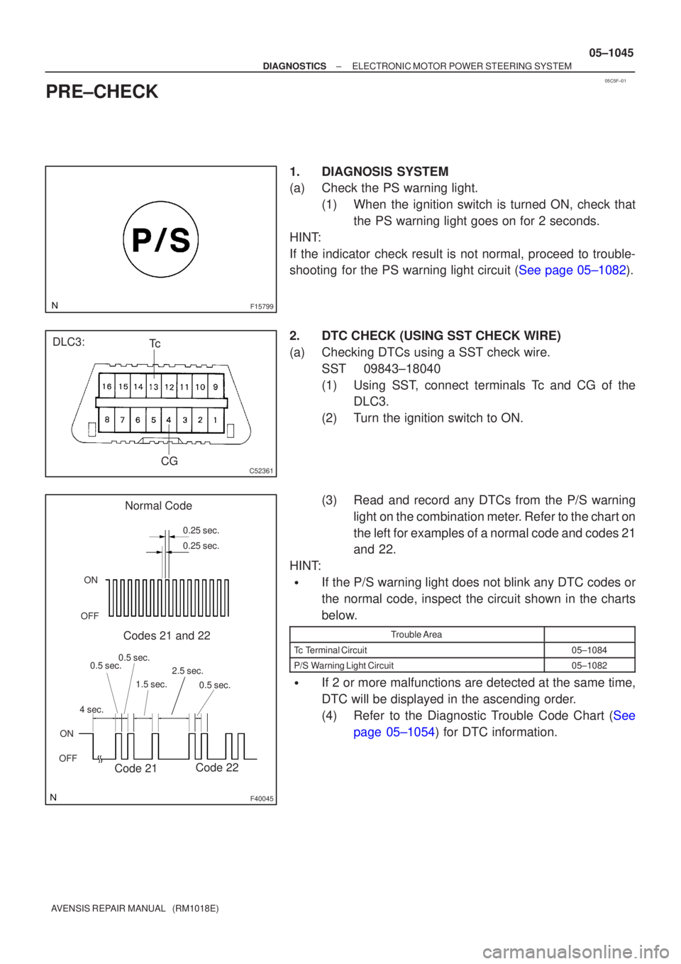
1.DIAGNOSIS SYSTEM
(a)Check the PS warning light.
(1)When the ignition switch is turned ON, check thatthe PS warning light goes on for 2 seconds.
HINT:
If the indicator check result is not normal, proceed to trouble-
shooting for the PS warning light circuit (See page 05±1082).
2.DTC CHECK (USING SST CHECK WIRE)
(a)Checking DTCs using a SST check wire. SST09843±18040
(1)Using SST, connect terminals Tc and CG of theDLC3.
(2)Turn the ignition switch to ON.
(3)Read and record any DTCs from the P/S warning light on the combination meter. Refer to the chart on
the left for examples of a normal code and codes 21
and 22.
HINT:
�If the P/S warning light does not blink any DTC codes or
the normal code, inspect the circuit shown in the charts
below.
Trouble Area
Tc Terminal Circuit05±1084
P/S Warning Light Circuit05±1082
�If 2 or more malfunctions are detected at the same time,
DTC will be displayed in the ascending order.
(4)Refer to the Diagnostic Trouble Code Chart (See page 05±1054) for DTC information.
Page 1090 of 5135
C52361
DLC3:
CGTs 05±1046
± DIAGNOSTICSELECTRONIC MOTOR POWER STEERING SYSTEM
AVENSIS REPAIR MANUAL (RM1018E)
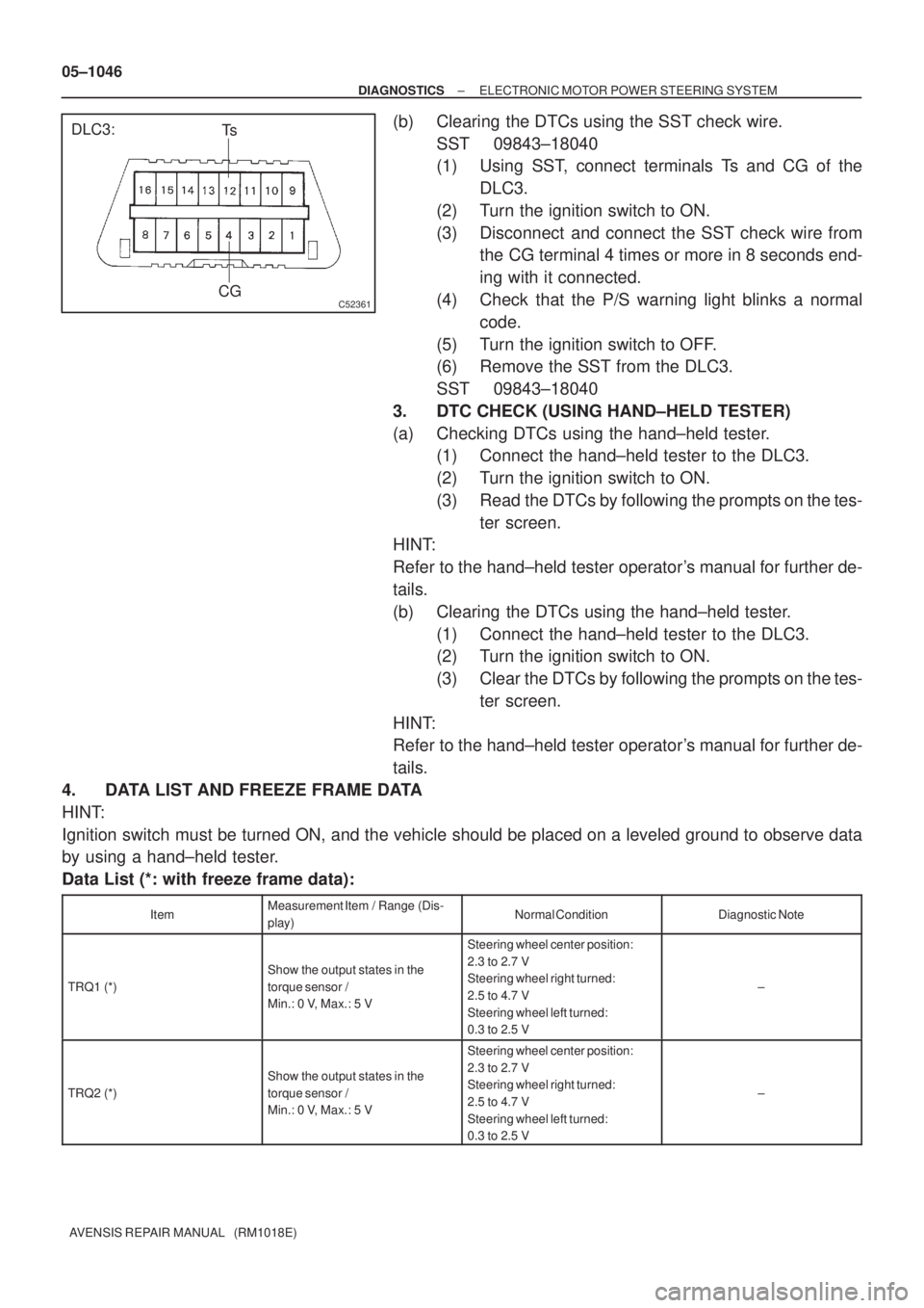
(b) Clearing the DTCs using the SST check wire.
SST 09843±18040
(1) Using SST, connect terminals Ts and CG of the
DLC3.
(2) Turn the ignition switch to ON.
(3) Disconnect and connect the SST check wire from
the CG terminal 4 times or more in 8 seconds end-
ing with it connected.
(4) Check that the P/S warning light blinks a normal
code.
(5) Turn the ignition switch to OFF.
(6) Remove the SST from the DLC3.
SST 09843±18040
3. DTC CHECK (USING HAND±HELD TESTER)
(a) Checking DTCs using the hand±held tester.
(1) Connect the hand±held tester to the DLC3.
(2) Turn the ignition switch to ON.
(3) Read the DTCs by following the prompts on the tes-
ter screen.
HINT:
Refer to the hand±held tester operator's manual for further de-
tails.
(b) Clearing the DTCs using the hand±held tester.
(1) Connect the hand±held tester to the DLC3.
(2) Turn the ignition switch to ON.
(3) Clear the DTCs by following the prompts on the tes-
ter screen.
HINT:
Refer to the hand±held tester operator's manual for further de-
tails.
4. DATA LIST AND FREEZE FRAME DATA
HINT:
Ignition switch must be turned ON, and the vehicle should be placed on a leveled ground to observe data
by using a hand±held tester.
Data List (*: with freeze frame data):
ItemMeasurement Item / Range (Dis-
play)Normal ConditionDiagnostic Note
TRQ1 (*)
Show the output states in the
torque sensor /
Min.: 0 V, Max.: 5 V
Steering wheel center position:
2.3 to 2.7 V
Steering wheel right turned:
2.5 to 4.7 V
Steering wheel left turned:
0.3 to 2.5 V
±
TRQ2 (*)
Show the output states in the
torque sensor /
Min.: 0 V, Max.: 5 V
Steering wheel center position:
2.3 to 2.7 V
Steering wheel right turned:
2.5 to 4.7 V
Steering wheel left turned:
0.3 to 2.5 V
±
Page 1092 of 5135
C52361
DLC3:CGTs
Tc
F42646
Malfunction Code (Example Code 73)
7 3
ON
OFF
0.5 sec.
0.5 sec.
0.5 sec. 4 sec.
Repeat
0.5 sec.
ON
OFF
0.25 sec.
0.25 sec.
Normal Code
A Cycle 1.5 sec.
05±1048
±
DIAGNOSTICS ELECTRONIC MOTOR POWER STEERING SYSTEM
AVENSIS REPAIR MANUAL (RM1018E)
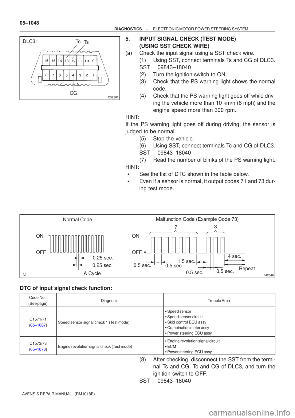
5.INPUT SIGNAL CHECK (TEST MODE) (USING SST CHECK WIRE)
(a)Check the input signal using a SST check wire.
(1)Using SST, connect terminals Ts and CG of DLC3.
SST09843±18040
(2)Turn the ignition switch to ON.
(3)Check that the PS warning light shows the normalcode.
(4)Check that the PS warning light goes off while driv- ing the vehicle more than 10 km/h (6 mph) and the
engine speed more than 300 rpm.
HINT:
If the PS warning light goes off during driving, the sensor is
judged to be normal.
(5)Stop the vehicle.
(6)Using SST, connect terminals Tc and CG of DLC3.
SST09843±18040
(7)Read the number of blinks of the PS warning light.
HINT:
�See the list of DTC shown in the table below.
�Even if a sensor is normal, it output codes 71 and 73 dur-
ing test mode.
DTC of input signal check function:
Code No.
(See page)DiagnosisTrouble Area
C1571/71
(05±1067)Speed sensor signal check 1 (Test mode)
� Speed sensor
� Speed sensor circuit
� Skid control ECU assy
� Combination meter assy
� Power steering ECU assy
C1573/73
(05±1070)Engine revolution signal check (Test mode)
� Engine revolution signal circuit
� ECM
� Power steering ECU assy
(8) After checking, disconnect the SST from the termi-
nal Ts and CG, Tc and CG of DLC3, and turn the
ignition switch to OFF.
SST 09843±18040