Page 1093 of 5135
C52361
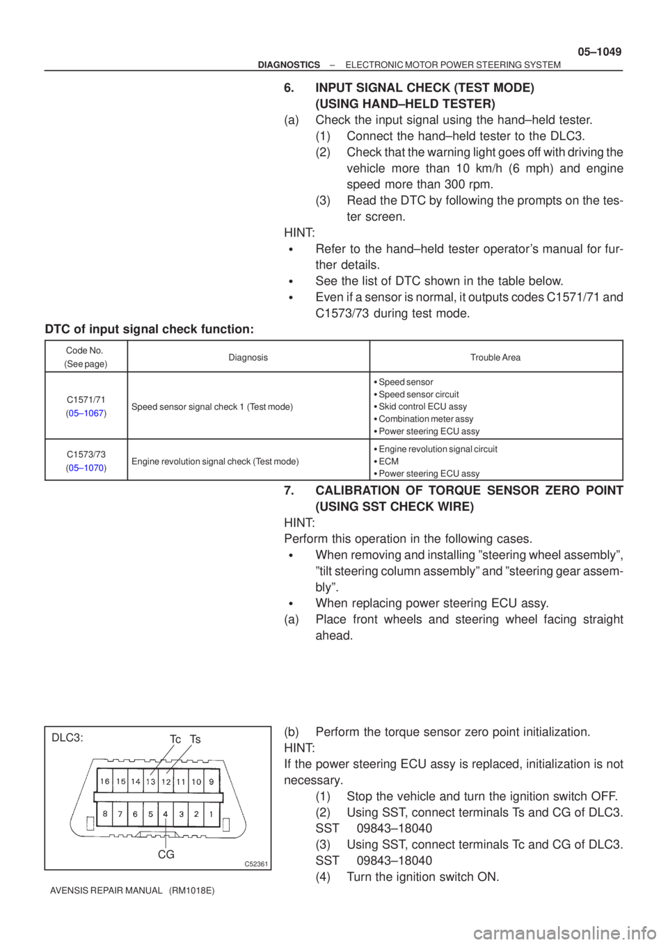
DLC3:CGTs
Tc
±
DIAGNOSTICS ELECTRONIC MOTOR POWER STEERING SYSTEM
05±1049
AVENSIS REPAIR MANUAL (RM1018E)
6.INPUT SIGNAL CHECK (TEST MODE)
(USING HAND±HELD TESTER)
(a)Check the input signal using the hand±held tester.
(1)Connect the hand±held tester to the DLC3.
(2)Check that the warning light goes off with driving thevehicle more than 10 km/h (6 mph) and engine
speed more than 300 rpm.
(3)Read the DTC by following the prompts on the tes- ter screen.
HINT:
�Refer to the hand±held tester operator's manual for fur-
ther details.
�See the list of DTC shown in the table below.
�Even if a sensor is normal, it outputs codes C1571/71 and
C1573/73 during test mode.
DTC of input signal check function:
Code No.
(See page)DiagnosisTrouble Area
C1571/71
(05±1067)Speed sensor signal check 1 (Test mode)
� Speed sensor
� Speed sensor circuit
� Skid control ECU assy
� Combination meter assy
� Power steering ECU assy
C1573/73
(05±1070)Engine revolution signal check (Test mode)
� Engine revolution signal circuit
� ECM
� Power steering ECU assy
7. CALIBRATION OF TORQUE SENSOR ZERO POINT
(USING SST CHECK WIRE)
HINT:
Perform this operation in the following cases.
�When removing and installing ºsteering wheel assemblyº,
ºtilt steering column assemblyº and ºsteering gear assem-
blyº.
�When replacing power steering ECU assy.
(a) Place front wheels and steering wheel facing straight ahead.
(b) Perform the torque sensor zero point initialization.
HINT:
If the power steering ECU assy is replaced, initialization is not
necessary. (1) Stop the vehicle and turn the ignition switch OFF.
(2) Using SST, connect terminals Ts and CG of DLC3.
SST 09843±18040
(3) Using SST, connect terminals Tc and CG of DLC3.
SST 09843±18040
(4) Turn the ignition switch ON.
Page 1098 of 5135
050Y7±04
Inspector 's
Name:
Customer 's Name
Date Vehicle
Brought InLicence No.
Odometer Reading/ /
/ /
Date Problem First Occurred
Frequency Problem Occurs
ContinuousIntermittent ( times a day)
Steering operation is heavy.
Steering force to the right and left differs, or steering force is uneven.
PS Warning Light
AbnormalRemains ONDoes not come on
DTC Check1st Time
2nd TimeNormal Code
Malfunction Code (Code )
Normal CodeMalfunction Code (Code )
Symptomskm
miles
EMPS Check Sheet
While running, the steering force does not alter corresponding the vehicle
speed.
Vibration or strange sound comes from the steering column assy.
A malfunction code is outputed at the first time, record the freeze frame data as well (as the DTCs). Freeze Frame Data
When a trouble happens
(
During turningDuring vehicle stopAlways)
OthersCooled Warmed up
/ /Engine() Vehicle Model
The steering returns unwell.
Production Date VIN 05±1044
± DIAGNOSTICSELECTRONIC MOTOR POWER STEERING SYSTEM
AVENSIS REPAIR MANUAL (RM1018E)
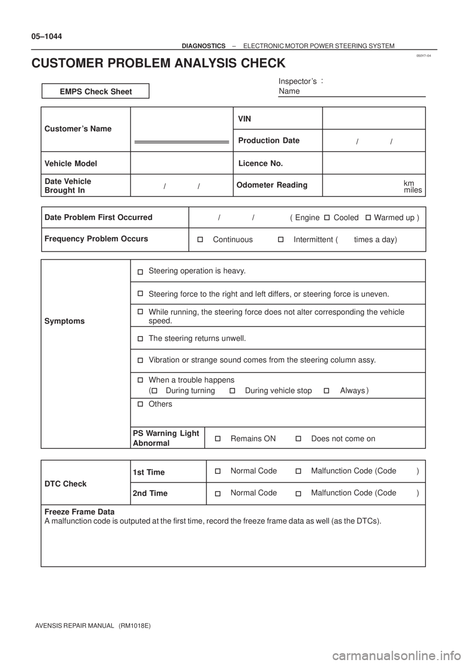
CUSTOMER PROBLEM ANALYSIS CHECK
Page 1122 of 5135
F44861
B±W22
C11Combination Meter
Driver Side J/B
Engine Room R/B No.4 Engine Room R/B No.1 and
Engine Room J/B No.1Power Steering
ECU Assy
6
C11
17
C10B±W
W±B
W±B
B±WP/S
J8C
AM2 J26A
J8C
J26A J/C
B±WB±R
B±R B±R B±R
B±RB±GB±G
B±G (*1) (*2) (*1) (*2)(*1)
(*2)
18
DA2
DH IGN
IE41
IP11
(*1) (*2)
1
1A1
111
4A
4B
2AM2 IG2 I13
Ignition SWE159
WL
46
FL MAIN
BatteryJ15
J/CJ16
J/C
IK
IO AA
*1: LHD
*2: RHDA
AJ17
J/C
A W±B
(*2)
W±B
(*1) 05±1082
± DIAGNOSTICSELECTRONIC MOTOR POWER STEERING SYSTEM
AVENSIS REPAIR MANUAL (RM1018E)
EMPS Warning Light Circuit
CIRCUIT DESCRIPTION
If the power steering ECU assy detects a trouble, the PS warning lights up. At this time, the power steering
ECU assy records a DTC in memory.
WIRING DIAGRAM
05C5I±01
Page 1123 of 5135
F44851
E14PGND
F44869
E15WL
±
DIAGNOSTICS ELECTRONIC MOTOR POWER STEERING SYSTEM
05±1083
AVENSIS REPAIR MANUAL (RM1018E)
INSPECTION PROCEDURE
NOTICE:
When performing the inspection of power steering ECU, ECU must be instal\
led to the vehicle or fully
fixed.
1CHECK HARNESS AND CONNECTOR(POWER STEERING ECU ASSY ±
COMBINATION METER ASSY)
(a)Check for an open or short circuit in harness and connector between power ste\
ering ECU assy and
combination meter assy (See page 01±32).
NGREPAIR OR REPLACE HARNESS ORCONNECTOR
OK
2CHECK HARNESS AND CONNECTOR(POWER STEERING ECU ASSY ± BODY GROUND)
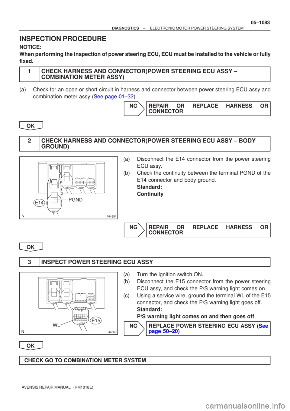
(a)Disconnect the E14 connector from the power steering
ECU assy.
(b)Check the continuity between the terminal PGND of the
E14 connector and body ground.
Standard:
Continuity
NGREPAIR OR REPLACE HARNESS OR CONNECTOR
OK
3INSPECT POWER STEERING ECU ASSY
(a)Turn the ignition switch ON.
(b)Disconnect the E15 connector from the power steering ECU assy, and check the P/S warning light comes on.
(c)Using a service wire, ground the terminal WL of the E15 connector, and check the P/S warning light goes off.
Standard:
P/S warning light comes on and then goes off
NGREPLACE POWER STEERING ECU ASSY (See page 50±20)
OK
CHECK GO TO COMBINATION METER SYSTEM
Page 1225 of 5135
050YH±19
±
DIAGNOSTICS SUPPLEMENTAL RESTRAINT SYSTEM
05±1197
AVENSIS REPAIR MANUAL (RM1018E)
PROBLEM SYMPTOMS TABLE
HINT:
Proceed the troubleshooting for each circuit in the below table.
SymptomSuspect AreaSee page
�When the ignition switch is ON, the SRS warning light some-
times come on after approx. 6 seconds.
�SRS warning light circuit malfunction
�SRS warning light is always lit up even when ignition switch is in
the LOCK position.
SRS warning light circuit malfunction
(Always lights up, when ignition switch is LOCK position).05±1386
� With the ignition switch is ON, the SRS warning light does not
come on.�SRS warning light circuit malfunction
(Does not light up, when ignition switch is turned to ON).05±1389
�DTC is not displayed.
�SRS warning light is always on at the time of DTC check proce-
dure.�TC terminal circuit05±1391
�DTC is displayed without connecting TC and CG terminal.
Page 1226 of 5135
05C5W±01
H40533
A26A27
A28
± DIAGNOSTICSSUPPLEMENTAL RESTRAINT SYSTEM
05±1195
AVENSIS REPAIR MANUAL (RM1018E)
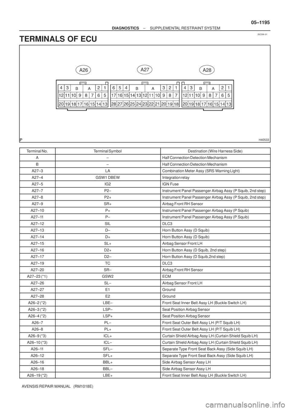
TERMINALS OF ECU
Terminal No.Terminal SymbolDestination (Wire Harness Side)
A±Half Connection Detection Mechanism
B±Half Connection Detection Mechanism
A27±3LACombination Meter Assy (SRS Warning Light)
A27±4GSW1 DBEWIntegration relay
A27±5IG2IGN Fuse
A27±7P2±Instrument Panel Passenger Airbag Assy (P Squib, 2nd step)
A27±8P2+Instrument Panel Passenger Airbag Assy (P Squib, 2nd step)
A27±9SR+Airbag Front RH Sensor
A27±10P+Instrument Panel Passenger Airbag Assy (P Squib)
A27±11P±Instrument Panel Passenger Airbag Assy (P Squib)
A27±12SILDLC3
A27±13D±Horn Button Assy (D Squib)
A27±14D+Horn Button Assy (D Squib)
A27±15SL+Airbag Sensor Front LH
A27±16D2+Horn Button Assy (D Squib, 2nd step)
A27±17D2±Horn Button Assy (D Squib,2nd step)
A27±19TCDLC3
A27±20SR±Airbag Front RH Sensor
A27±23 (*1)GSW2ECM
A27±26SL±Airbag Sensor Front LH
A27±27E1Ground
A27±28E2Ground
A26±2 (*2)LBE±Front Seat Inner Belt Assy LH (Buckle Switch LH)
A26±3 (*2)LSP±Seat Position Airbag Sensor
A26±4 (*2)LSP+Seat Position Airbag Sensor
A26±7PL±Front Seat Outer Belt Assy LH (P/T Squib LH)
A26±8PL+Front Seat Outer Belt Assy LH (P/T Squib LH)
A26±9 (*3)ICL+Curtain Shield Airbag Assy LH (Curtain Shield Squib LH)
A26±10 (*3)ICL±Curtain Shield Airbag Assy LH (Curtain Shield Squib LH)
A26±11SFL±Separate Type Front Seat Back Assy (Side Squib LH)
A26±12SFL+Separate Type Front Seat Back Assy (Side Squib LH)
A26±16BBL+Side Airbag Sensor Assy LH
A26±18BBL±Side Airbag Sensor Assy LH
A26±19 (*2)LBE+Front Seat Inner Belt Assy LH (Buckle Switch LH)
Page 1228 of 5135
050X1±21
H42508
Instrument Panel Passenger Airbag Assy
Separate Type Front Seat Back
Assy (Side Squib RH)
Side Airbag
Sensor Assy LH Airbag Sensor
Front LH
Front Seat Outer Belt Assy LHFront Seat Outer Belt Assy RH Airbag Front RH Sensor Combination Meter Assy:
Curtain Shield Airbag Assy RH (*3)
Airbag Sensor
Rear RH (*3) Seat Position
Airbag Sensor Curtain Shield
Airbag Assy LH
(*3)
Horn Button Assy
Airbag Sensor Assy Center Airbag Sensor
Rear LH (*3)Side Airbag Sensor Assy RH
Front Seat Inner Belt Assy LH (*1) Spiral Cable
Sub±assy
Separate Type
Front Seat
Back Assy
(Side Squib LH)
SRS Warning Light
Instrument
Panel
Airbag Assy
*1: LHD
*2: RHD
*3: w/ Curtain Shield Airbag 05±1194
± DIAGNOSTICSSUPPLEMENTAL RESTRAINT SYSTEM
AVENSIS REPAIR MANUAL (RM1018E)
LOCATION
Page 1229 of 5135
050WZ±17
05±1190
±
DIAGNOSTICS SUPPLEMENTAL RESTRAINT SYSTEM
AVENSIS REPAIR MANUAL (RM1018E)
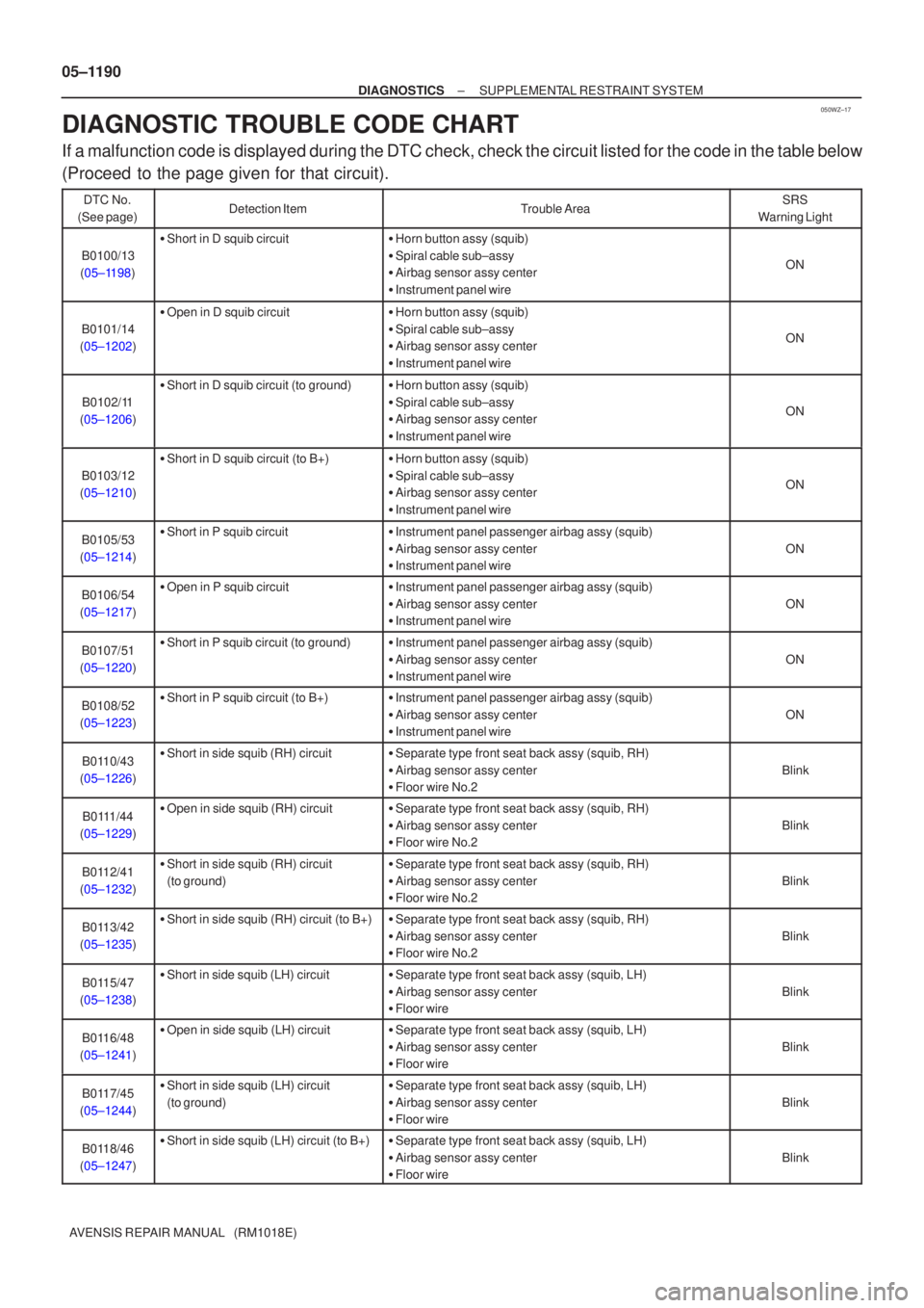
DIAGNOSTIC TROUBLE CODE CHART
If a malfunction code is displayed during the DTC check, check the circuit\
listed for the code in the table below
(Proceed to the page given for that circuit).
DTC No.
(See page)Detection ItemTrouble AreaSRS
Warning Light
B0100/13
(05±1198)
� Short in D squib circuit�Horn button assy (squib)
� Spiral cable sub±assy
� Airbag sensor assy center
� Instrument panel wire
ON
B0101/14
(05±1202)
� Open in D squib circuit�Horn button assy (squib)
� Spiral cable sub±assy
� Airbag sensor assy center
� Instrument panel wire
ON
B0102/11
(05±1206)
� Short in D squib circuit (to ground)�Horn button assy (squib)
� Spiral cable sub±assy
� Airbag sensor assy center
� Instrument panel wire
ON
B0103/12
(05±1210)
� Short in D squib circuit (to B+)�Horn button assy (squib)
� Spiral cable sub±assy
� Airbag sensor assy center
� Instrument panel wire
ON
B0105/53
(05±1214)� Short in P squib circuit�Instrument panel passenger airbag assy (squib)
� Airbag sensor assy center
� Instrument panel wire
ON
B0106/54
(05±1217)� Open in P squib circuit�Instrument panel passenger airbag assy (squib)
� Airbag sensor assy center
� Instrument panel wire
ON
B0107/51
(05±1220)� Short in P squib circuit (to ground)�Instrument panel passenger airbag assy (squib)
� Airbag sensor assy center
� Instrument panel wire
ON
B0108/52
(05±1223)� Short in P squib circuit (to B+)�Instrument panel passenger airbag assy (squib)
� Airbag sensor assy center
� Instrument panel wire
ON
B0110/43
(05±1226)� Short in side squib (RH) circuit�Separate type front seat back assy (squib, RH)
� Airbag sensor assy center
� Floor wire No.2
Blink
B0111/44
(05±1229)� Open in side squib (RH) circuit�Separate type front seat back assy (squib, RH)
� Airbag sensor assy center
� Floor wire No.2
Blink
B0112/41
(05±1232)� Short in side squib (RH) circuit
(to ground)�Separate type front seat back assy (squib, RH)
� Airbag sensor assy center
� Floor wire No.2
Blink
B0113/42
(05±1235)� Short in side squib (RH) circuit (to B+)�Separate type front seat back assy (squib, RH)
� Airbag sensor assy center
� Floor wire No.2
Blink
B0115/47
(05±1238)� Short in side squib (LH) circuit�Separate type front seat back assy (squib, LH)
� Airbag sensor assy center
� Floor wire
Blink
B0116/48
(05±1241)� Open in side squib (LH) circuit�Separate type front seat back assy (squib, LH)
� Airbag sensor assy center
� Floor wire
Blink
B0117/45
(05±1244)� Short in side squib (LH) circuit
(to ground)�Separate type front seat back assy (squib, LH)
� Airbag sensor assy center
� Floor wire
Blink
B0118/46
(05±1247)� Short in side squib (LH) circuit (to B+)�Separate type front seat back assy (squib, LH)
� Airbag sensor assy center
� Floor wire
Blink