Page 1573 of 5135
I35765
I14
Body ECUCombination Meter Assy
14
C10 1
IC1
P±B MPX2
P±B
MPX1 11
P 10
IC1 29
A13 20
A15
10 9
3 24
A16P±B MPX±
MPX+
PBLT A/C Control Assembly
F19 Front Passenger's
Seat Belt Warning LightECM
B10 Front Seat Inner Belt Assy
(Occupant Detection Sensor)
to GAUGE Fuse
*1: Except Automatic A/C
*2: Automatic A/C
*3: 1AZ±FSE
*4: 1AZ±FE, 1ZZ±FE, 3ZZ±FE
*5: 1CD±FTV
*6: Except 1AZ±FE21 29
E1029
(*5) (*3) (*4)MPX2
20 1823
13
C10
1 3
W±B (*6) G±Y B±PBEW
IG
PBEW
E8 7 4 6
L±R
BV A15 A13
A13
(*5) (*3) (*4) (*2) (*1)
(*1) (*2)
(*1) (*2)E9
MPX1
P P
(*6) 14
IM1
G±Y (*6)
W±B LHD Models:
22
(*6)
R±W(*6)
BU
IPW±B 6 9
CHCA W±B (*6)Center J/BE9
E10 E9 E9
± DIAGNOSTICSCOMBINATION METER
05±1525
AVENSIS REPAIR MANUAL (RM1018E)
Page 1574 of 5135

INSPECTION PROCEDURE
1 CHECK FRONT SEAT INNER BELT ASSY
(a) Check resistance.
(1) Disconnect the connector from front")
E66856
05±1526
± DIAGNOSTICSCOMBINATION METER
AVENSIS REPAIR MANUAL (RM1018E)
INSPECTION PROCEDURE
1 CHECK FRONT SEAT INNER BELT ASSY
(a) Check resistance.
(1) Disconnect the connector from front seat inner belt
assy.
(2) Check resistance between the terminal 3 and 1 of
the front seat inner belt assy.
Standard:
ConditionSpecified Condition
Seat belt is fastenedNo continuity
Seat belt is unfastenedContinuity
NG REPLACE FRONT SEAT INNER BELT ASSY
OK
2 CHECK HARNESS OR CONNECTOR(A/C CONTROL ASSEMBLY±FRONT SEAT
INNER BELT ASSY)
(a) Check continuity between the terminal A13±24 / A16±3 of A/C control assembly and the terminal
F19±3 (6) of front passenger's seat belt warning light.
( ): LHD models
(b) Check continuity between the terminal F19±2 (F19±7)of front passenger's seat belt warning light and
the terminal B10±3 of front seat inner belt assy.
( ): LHD models
Standard: Continuity
NG REPAIR OR REPLACE HARNESS OR
CONNECTOR
OK
3 CHECK THAT MALFUNCTION DISAPPEARS A KNOWN GOOD COMBINATION
METER IS INSTALLED
NG CHECK AND REPLACE AIR CONDITIONER
CONTROL ASSEMBLY
OK
CHECK AND REPLACE COMBINATION METER ASSY
Page 1575 of 5135
I35763
I14
Body ECU
B9
Front Seat Inner Belt AssyCombination Meter Assy
Airbag Sensor AssemblyDriver Side J/B
*1: LHD Models
*2: RHD Models14
C10 1
IC1
12
IC114
DB2
DD
L±R P±B
L±R
G±Y
W±B 3
1 MPX2
BKLP±B
9 22
4
A27
19
A26 14
A28
2 3LBE+
RBE+
LBE±
RBE±(*1)
(*2) A26 A28(*1)
(*2) L±R
GSW
(*1) (*2)
(*1) (*2)DBEW(*1)
(*2)
05±1522
± DIAGNOSTICSCOMBINATION METER
AVENSIS REPAIR MANUAL (RM1018E)
SEAT BELT WARNING LAMP FOR DRIVER'S SEAT DOES NOT
OPERATE
WIRING DIAGRAM
INSPECTION PROCEDURE
1 READ VALUE OF HAND±HELD TESTER
(a) Operate the hand±held tester according to the steps on the display and select ºDATA LISTº.
BGW(Body):
ItemMeasurement Item/
Range (Display)Normal ConditionDiagnostic Note
D SEAT BUCKL SWDriver seat belt buckle switch ON /
OFFON: Fasten the driver seat belt
OFF: Unfasten the driver seat belt±
OK CHECK AND REPLACE COMBINATION METER
ASSY
NG
05C4M±01
Page 1589 of 5135
B66771
KSW
W±B8 U1
Unlock Warning Switch Assy
W±B
IP5
+B GROUND 1
W±R W±B
2
1Instrument Panel J/B Assy
PRG
RDA 16
2PRG
RDA D6
Door Control Receiver
7Integration
Relay
IC2 I14 3 G±Y
L±W 16
7
To
Battery
DA Y
IO*
1
6 8
Center
J/BIC2 G±Y
L±W
CA CD
AJ16
J/C LHD Models
19 I14
A W±B
IL*
2*1: Gasoline Engine
*2: 1CD±FTV
± DIAGNOSTICSWIRELESS DOOR LOCK CONTROL SYSTEM
05±1575
AVENSIS REPAIR MANUAL (RM1018E)
ONLY WIRELESS CONTROL FUNCTION DOES NOT OPERATE
(PREPARE NEW OR NORMAL TRANSMITTER OF THE SAME
TYPE VEHICLE)
CIRCUIT DESCRIPTION
The door control receiver receives a signal from the transmitter and sends this signal to the integration relay.
Then, the integration relay controls door operation by sending a door LOCK/UNLOCK signal and a luggage
door (back door) unlock signal to each door lock motor.
WIRING DIAGRAM
05BNB±01
Page 1590 of 5135
B66770
KSW
W±B8 U1
Unlock Warning Switch Assy
IP 5
+B GROUND 1
W±R W±B
2 1Instrument Panel J/B Assy
PRG
RDA 16
2PRG
RDA D6
Door Control Receiver
7Integration
Relay
IC2 I14 3
G±Y
L±W 16
7
To
Battery
DA Y*
2
IKIC2 G±Y
L±W
13 6
CF CA19 RHD Models
DJ22
J/C*
2
D
Center J/B
W±B Y*2
*1: 1AZ±FE
*
2: Except 1AZ±FEY*
1
A
J15
J/CI14 05±1576
± DIAGNOSTICSWIRELESS DOOR LOCK CONTROL SYSTEM
AVENSIS REPAIR MANUAL (RM1018E)
Page 1595 of 5135
B51903
PushedFree
B66769
DA
Instrument Panel J/B AssyU1
Unlock Warning Switch Wire Harness Side
KSW
± DIAGNOSTICSWIRELESS DOOR LOCK CONTROL SYSTEM
05±1581
AVENSIS REPAIR MANUAL (RM1018E)
11 INSPECT UNLOCK WARNING SWITCH ASSY
(a) Check the resistance of the switch.
Standard:
Tester ConnectionSwitch PositionSpecified Condition
12
Switch free
(Key removed)10 k� or higher
1 ± 2Switch pushed
(Key set)Below 1 �
NG REPLACE UNLOCK WARNING SWITCH ASSY
OK
12 CHECK WIRE HARNESS (UNLOCK WARNING SWITCH ± INSTRUMENT PANEL
J/B ASSY (INTEGRATION RELAY) AND BODY GROUND)
(a) Disconnect the U1 warning switch connector.
(b) Disconnect the DA J/B connector.
(c) Check the resistance of the wire harness side connectors.
Standard:
Tester ConnectionSpecified Condition
U1±2 ± DA±8 (KSW)Below 1�U1±1 ± Body groundBelow 1 �
NG REPAIR OR REPLACE HARNESS AND
CONNECTOR
OK
Page 1598 of 5135
056Q3±04
05±1574
±
DIAGNOSTICS WIRELESS DOOR LOCK CONTROL SYSTEM
AVENSIS REPAIR MANUAL (RM1018E)
PROBLEM SYMPTOMS TABLE
SymptomSuspected AreaSee Page
Only wireless control function does not operate
(Prepare new or normal transmitter of the same type vehicle)
8. Transmitter battery
9. Door transmitter sub±assy module set door control
10.Door control receiver
11. Unlock warning switch assy
12.Wire harness
13.Instrument panel J/B assy (Integration relay)
05±1575
No answer±back (Hazard warning lamp)
1. Lighting system
2. Wire harness
3. Instrument panel J/B assy (Integration relay)
05±1584
Page 1601 of 5135
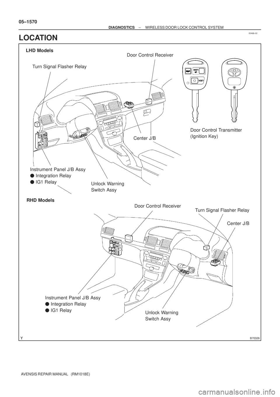
05A68±02
B70326
Door Control Transmitter
(Ignition Key)
Unlock Warning
Switch Assy
Instrument Panel J/B Assy
� Integration Relay
� IG1 Relay
Unlock Warning
Switch Assy
Door Control Receiver
Door Control Receiver
LHD Models
RHD Models
Center J/B
Center J/B
Instrument Panel J/B Assy
� Integration Relay
� IG1 Relay Turn Signal Flasher Relay
Turn Signal Flasher Relay
05±1570
± DIAGNOSTICSWIRELESS DOOR LOCK CONTROL SYSTEM
AVENSIS REPAIR MANUAL (RM1018E)
LOCATION


11 INSPEC")

PROBLEM SYMPTOMS TABLE
SymptomSuspected AreaSee Page
Only wireless control function does not opera")