Page 1734 of 5135
������
������B68389
Wire Harness Side
T15
Theft Warning Siren Assy T6
Theft Warning ECU Assy
B68388
Wire Harness Side
T15
Theft Warning Siren Assy
± DIAGNOSTICSTHEFT DETERRENT SYSTEM
05±1649
AVENSIS REPAIR MANUAL (RM1018E)
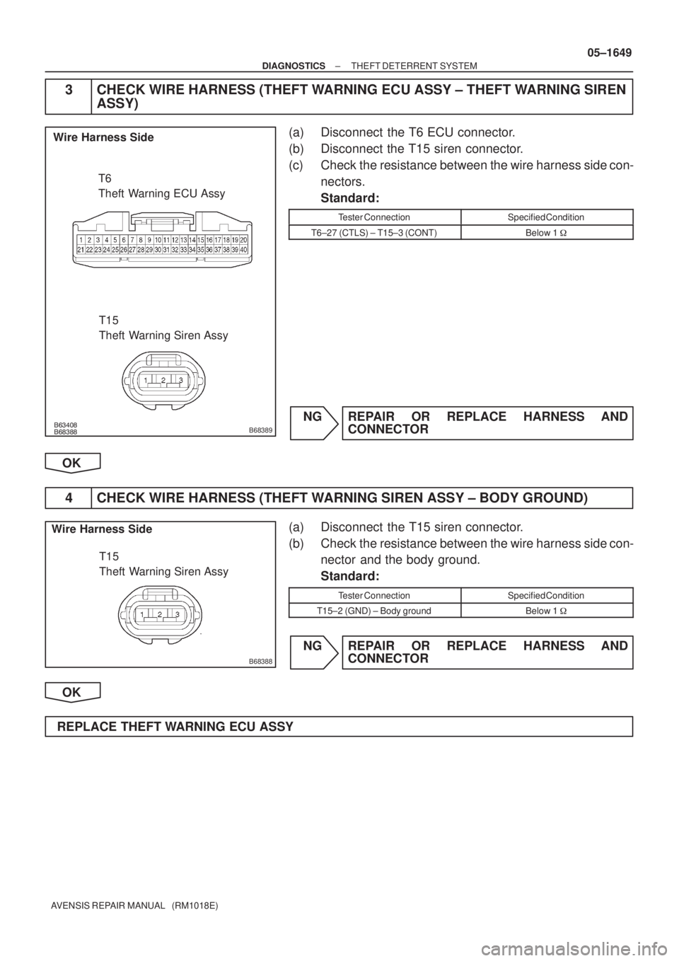
3 CHECK WIRE HARNESS (THEFT WARNING ECU ASSY ± THEFT WARNING SIREN
ASSY)
(a) Disconnect the T6 ECU connector.
(b) Disconnect the T15 siren connector.
(c) Check the resistance between the wire harness side con-
nectors.
Standard:
Tester ConnectionSpecified Condition
T6±27 (CTLS) ± T15±3 (CONT)Below 1 �
NG REPAIR OR REPLACE HARNESS AND
CONNECTOR
OK
4 CHECK WIRE HARNESS (THEFT WARNING SIREN ASSY ± BODY GROUND)
(a) Disconnect the T15 siren connector.
(b) Check the resistance between the wire harness side con-
nector and the body ground.
Standard:
Tester ConnectionSpecified Condition
T15±2 (GND) ± Body groundBelow 1 �
NG REPAIR OR REPLACE HARNESS AND
CONNECTOR
OK
REPLACE THEFT WARNING ECU ASSY
Page 1735 of 5135
B67701
Battery MainEngine Room R/B12
1T7
Theft Warning ECU Assy
G
HORN
B±G*
1
HORN Relay
G±W20
1H11
Horn
(Low) W
H12
Horn
(High)IE1J26
J/C
B
HORN5 Engine Room R/B No. 2
B G G
32
2 2 2
5
W
1
1A 1
1 3
3
B±G*
1
B*2
B*2
4A
4B1
1
*
1: Gasoline
*2: 1CD±FTV Engine Room
R/B No. 3 Engine
Room J/B
No. 4
G±W 05±1644
± DIAGNOSTICSTHEFT DETERRENT SYSTEM
AVENSIS REPAIR MANUAL (RM1018E)
HORN CIRCUIT
CIRCUIT DESCRIPTION
When the theft deterrent system is transferred from the armed state to the alarm sounding state, the theft
warning ECU switches on the HORN relay causing the horns to sound. The horn sounds at an interval of
0.4 seconds.
WIRING DIAGRAM
05BAF±01
Page 1737 of 5135
B63408
Wire Harness Side
T6
Theft Warning ECU Assy
������
������B68387
Wire Harness Side
H11
H12
Horn Assy Engine Room R/B No. 2
1
05±1646
± DIAGNOSTICSTHEFT DETERRENT SYSTEM
AVENSIS REPAIR MANUAL (RM1018E)
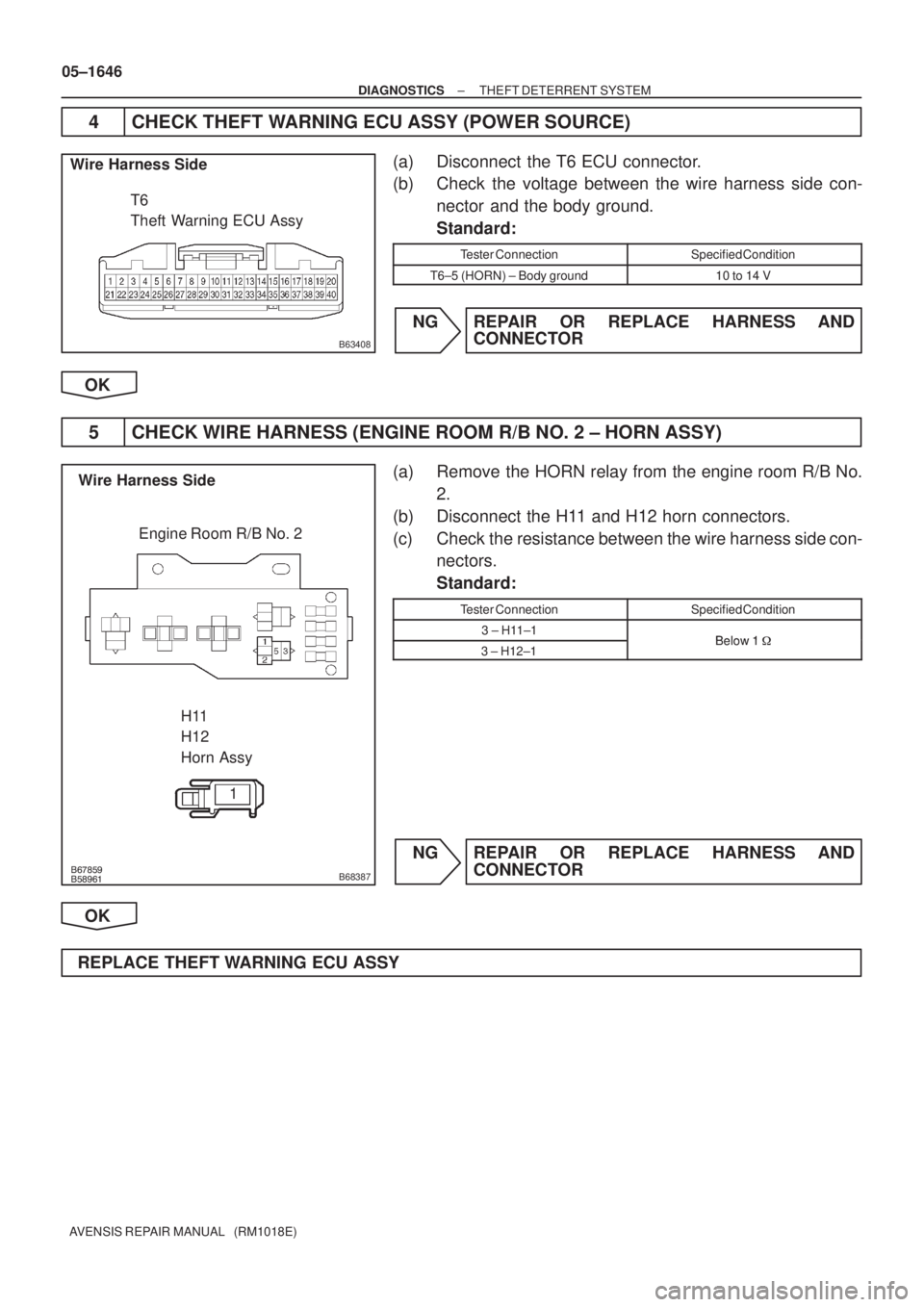
4 CHECK THEFT WARNING ECU ASSY (POWER SOURCE)
(a) Disconnect the T6 ECU connector.
(b) Check the voltage between the wire harness side con-
nector and the body ground.
Standard:
Tester ConnectionSpecified Condition
T6±5 (HORN) ± Body ground10 to 14 V
NG REPAIR OR REPLACE HARNESS AND
CONNECTOR
OK
5 CHECK WIRE HARNESS (ENGINE ROOM R/B NO. 2 ± HORN ASSY)
(a) Remove the HORN relay from the engine room R/B No.
2.
(b) Disconnect the H11 and H12 horn connectors.
(c) Check the resistance between the wire harness side con-
nectors.
Standard:
Tester ConnectionSpecified Condition
3 ± H11±1Below 1�3 ± H12±1Below 1 �
NG REPAIR OR REPLACE HARNESS AND
CONNECTOR
OK
REPLACE THEFT WARNING ECU ASSY
Page 1738 of 5135
B68375
E6
Engine Hood Courtesy Switch
W±B
1 3IO15
DSWH
34 L±RT6
Theft Warning ECU Assy
ECL±R
B67861
Free
(ON)
Pushed
(OFF)
05±1642
± DIAGNOSTICSTHEFT DETERRENT SYSTEM
AVENSIS REPAIR MANUAL (RM1018E)
ENGINE HOOD COURTESY SWITCH CIRCUIT
CIRCUIT DESCRIPTION
The engine hood courtesy switch is installed together with the hood lock assy. This switch comes on when
the engine hood is opened and goes off when the engine hood is closed.
WIRING DIAGRAM
INSPECTION PROCEDURE
1 INSPECT ENGINE HOOD COURTESY SWITCH
(a) Remove the engine hood courtesy switch from the hood
lock assy.
(b) Check the resistance.
Tester ConnectionSwitch PositionSpecified Condition
13Pushed (OFF (Lock))10 k� or higher1 ± 3Free (ON (Unlock))Below 1 �
NG REPAIR OR REPLACE ENGINE HOOD
COURTESY SWITCH
OK
05BAE±01
Page 1739 of 5135
������
������B68381
Wire Harness Side
E6
Engine Hood Courtesy SwitchT6
Theft Warning ECU Assy
B67857
Wire Harness Side
E6
Engine Hood Courtesy Switch
± DIAGNOSTICSTHEFT DETERRENT SYSTEM
05±1643
AVENSIS REPAIR MANUAL (RM1018E)
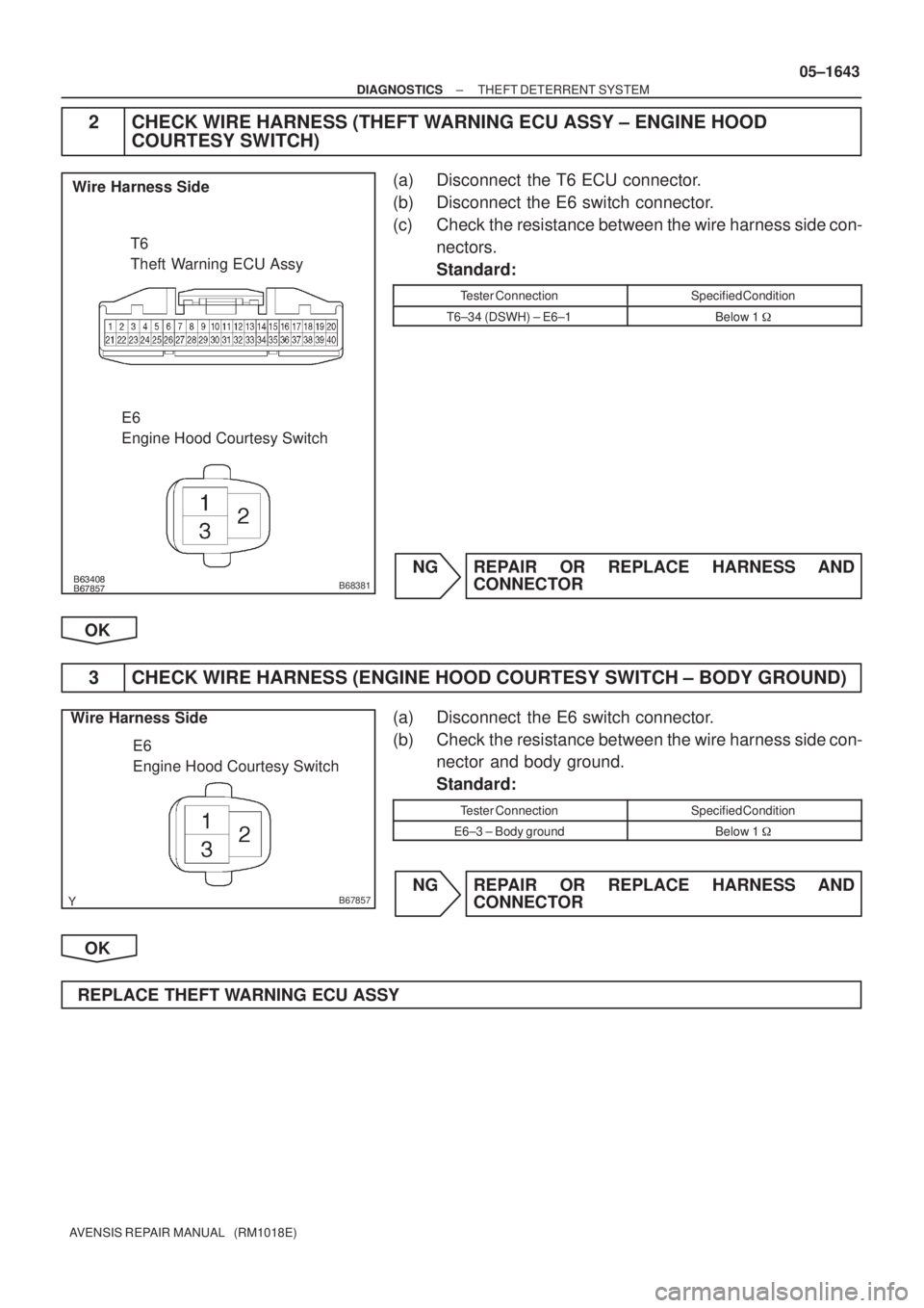
2 CHECK WIRE HARNESS (THEFT WARNING ECU ASSY ± ENGINE HOOD
COURTESY SWITCH)
(a) Disconnect the T6 ECU connector.
(b) Disconnect the E6 switch connector.
(c) Check the resistance between the wire harness side con-
nectors.
Standard:
Tester ConnectionSpecified Condition
T6±34 (DSWH) ± E6±1Below 1 �
NG REPAIR OR REPLACE HARNESS AND
CONNECTOR
OK
3 CHECK WIRE HARNESS (ENGINE HOOD COURTESY SWITCH ± BODY GROUND)
(a) Disconnect the E6 switch connector.
(b) Check the resistance between the wire harness side con-
nector and body ground.
Standard:
Tester ConnectionSpecified Condition
E6±3 ± Body groundBelow 1 �
NG REPAIR OR REPLACE HARNESS AND
CONNECTOR
OK
REPLACE THEFT WARNING ECU ASSY
Page 1779 of 5135
B67809
Battery113
31 MPX1P
Theft Warning ECU Assy
E10 18
H 22
J/C
+B
W±B*
5
T6 I14
MainW±R*
5
AIC1BEAN
(EFI)
B*
3
POWER
EARTH
3
Instrument Panel J/B Assy
(Integration Relay)
ECMCombination Meter Assy
(Combination Meter ECU)
E9 E923 20
C10
BEAN
(BODY) 14
C10 P±B P±B
BEAN
(SECURITY) 15
C10 P±L*
4
MPX2
MPX
20
C11
C1017 J11 J26 J10
J26F F
F
W±R*
6
W±R
6
6
12DOME
B±W IE4
IP14*
5
5*6
B±W
1
1 2
1A
B±G*
1,
2
B±G*1,
2B*3
3
1
1 4B 4A
W±B*6
A
J16
J/CJ17
J/C
IK
IO*
1,
2,
5
*1: 1AZ±FSE
*2: 1AZ±FE, 1ZZ±FE, 3ZZ±FE
*
3: 1CD±FTV
*
4: w/ Theft Deterrent System
*5: LHD
*
6: RHD *
1*2*3
Engine Room R/BFuse Block Assy
Engine Room J/B No. 4*1,
2Engine Room R/B No. 3*3
DCC
1
AA
W±B*
6
W±BA
J15
J/C
IL*
3,
5
05±1694
± DIAGNOSTICSMULTIPLEX COMMUNICATION SYSTEM
AVENSIS REPAIR MANUAL (RM1018E)
WIRING DIAGRAM
Page 1780 of 5135
B68156
C10
Combination Meter Assy
(Combination Meter ECU) Wire Harness Side
T6
Theft Warning ECU AssyE10
*1
ECM
E9
*2,
3
ECM
I14
Instrument Panel J/B Assy
(Integration Relay)
± DIAGNOSTICSMULTIPLEX COMMUNICATION SYSTEM
05±1695
AVENSIS REPAIR MANUAL (RM1018E)
1 CHECK RESISTANCE OF COMMUNICATION LINE
(a) Disconnect the C10, E10 or E9, T6 and I14 connectors.
(b) Check the resistance between wire harness side connec-
tors.
Standard:
Tester ConnectionSpecified Condition
*1
C10±13 (BEAN) (EFI) ±
E10±18 (MPX1)
*2
C10±13 (BEAN) (EFI) ±
E9±23 (MPX1)
*3
C10±13 (BEAN) (EFI) ±
E9±20 (MPX1)Below 1 �
C10±14 (BEAN) (BODY) ±
I14±22 (MPX2)
C10±15 (BEAN) (SECURITY) ±
T6±31 (MPX)
HINT:
*
1: 1AZ±FSE
*
2: 1AZ±FE, 1ZZ±FE, 3ZZ±FE
*
3: 1CD±FTV
NG REPAIR OR REPLACE HARNESS AND
CONNECTOR
OK
Page 1902 of 5135

AVENSIS REPAIR MANUAL (RM1018E)
FUEL FILTER ASSY (1CD±FTV)
REPLACEMENT
1. REMOVE AIR CLEANER ASSY
(a) Disconnect the conn")
110UD±01
A79188
A80091SST
A79190
11±82
± FUELFUEL FILTER ASSY (1CD±FTV)
AVENSIS REPAIR MANUAL (RM1018E)
FUEL FILTER ASSY (1CD±FTV)
REPLACEMENT
1. REMOVE AIR CLEANER ASSY
(a) Disconnect the connector.
(b) Remove the air cleaner cap with the air cleaner hose.
(c) Remove the air cleaner filter element.
(d) Remove the 3 bolts and the air cleaner case.
2. REMOVE FUEL FILTER ASSY
(a) Disconnect the 2 fuel hose from the fuel filter. (STD or COLD)
(b) Disconnect the 3 fuel hose from the fuel filter. (W/ ADDTIONAL HEATER)
(c) Disconnect the 2 connectors.
(d) Remove the 2 bolts and the fuel filter.
3. DRAIN FUEL
(a) Loosen the drain plug, and drain the fuel from the fuel filter.
4. REMOVE LEVEL WARNING SWITCH
(a) Clamp the fuel filter in a soft jaw vise.
(b) Using pliers, remove the level warning switch.
NOTICE:
Be careful not to damage the level warning switch.
5. REMOVE FUEL FILTER ELEMENT
(a) Using SST, remove the fuel filter element.
SST 09228±64030
6. INSTALL FUEL FILTER ELEMENT
(a) Check and clean the fuel filter installation surface.
(b) Apply fuel to a gasket of a new fuel filter element.
(c) Lightly screw the fuel filter element into place, and tighten
it until the gasket comes into contact with the seat.
(d) Tighten it additional 3/4 turn by hand.
 W
H12
Horn
(High)IE1J26
J/C
B
HORN5 Engine Room R/B No. 2
B G G
32
2 2 2
5
W
1
1A 1
1 3")

Pushed
(OFF)
05±1642
± DIAGNOSTICSTHEFT DETERRENT SYSTEM
AVENSIS REPAIR MANUAL (RM1")

B*
3
POWER
EARTH
3
Instrument Panel J/B Assy
(Integration Relay)
ECMCombination Meter As")
 Wire Harness Side
T6
Theft Warning ECU AssyE10
*1
ECM
E9
*2,
3
ECM
I14
Instrument Panel J/B Assy
(Integration Relay)
± DIAGNOSTICSMULT")