Page 1903 of 5135
±
FUEL FUEL FILTER ASSY(1CD±FTV)
11±83
AVENSIS REPAIR MANUAL (RM1018E)
7.INSTALL LEVEL WARNING SWITCH
(a)Install a new O±ring to the level warning switch.
(b)Apply fuel to the O±ring of the level warning switch.
(c)Install the level warning switch to the fuel filter by hand.
8.INSTALL FUEL FILTER ASSY
Torque: 18 N �m (178 kgf �cm, 13 ft �lbf)
9.INSTALL AIR CLEANER ASSY
Torque: 7.0 N �m (71 kgf �cm, 62 in. �lbf)
10.CHECK FOR FUEL LEAKS(See page 11±60)
Page 1929 of 5135
± FUELFUEL SYSTEM (1CD±FTV)
11±57
AVENSIS REPAIR MANUAL (RM1018E)
5. LEVEL WARNING SWITCH
(a) Continuity inspection.
(1) Using an ohmmeter, check that there is continuity between terminals.
Specified condition:
There is continuity when raising a float.
There is no continuity when letting a float down.
6. FUEL TEMPERATURE SENSOR
(a) Resistance inspection.
(1) Using an ohmmeter, measure the resistance between the terminals.
Resistance:
Approx. 20�C (68�F) 2.21 to 2.69 �
Approx. 80�C (176�F) 0.287 to 0.349 �
Page 2434 of 5135
B00540
A75980
Disconnect Wire
from Terminal B
Generator
Voltmeter BatteryAmmeter 19±6
± STARTING & CHARGINGCHARGING SYSTEM (1ZZ±FE/3ZZ±FE)
AVENSIS REPAIR MANUAL (RM1018E)
(b) Check that it fits properly in the ribbed grooves.
HINT:
Check with your hand to confirm that the belt has not slipped out
of the groove on the bottom of the pulley.
5. VISUALLY CHECK GENERATOR WIRING
(a) Check that the wiring is in good condition.
6. LISTEN FOR ABNORMAL NOISES FROM GENERATOR
(a) Check that there is no abnormal noise from the generator while the engine is running.
7. INSPECT CHARGE WARNING LIGHT CIRCUIT
(a) Turn the ignition switch ON. Check that the charge warning light comes on.
(b) Start the engine and check that the light goes off.
HINT:
If the light does not operate as specified, troubleshoot the charge warning light circuit.
8. INSPECT CHARGING CIRCUIT WITHOUT LOAD
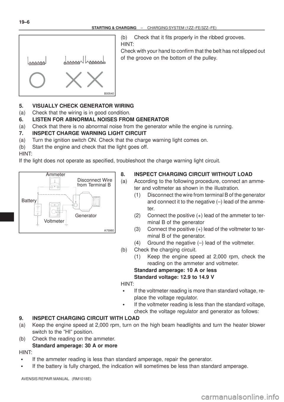
(a) According to the following procedure, connect an amme-
ter and voltmeter as shown in the illustration.
(1) Disconnect the wire from terminal B of the generator
and connect it to the negative (±) lead of the amme-
ter.
(2) Connect the positive (+) lead of the ammeter to ter-
minal B of the generator
(3) Connect the positive (+) lead of the voltmeter to ter-
minal B of the generator.
(4) Ground the negative (±) lead of the voltmeter.
(b) Check the charging circuit.
(1) Keep the engine speed at 2,000 rpm, check the
reading on the ammeter and voltmeter.
Standard amperage: 10 A or less
Standard voltage: 12.9 to 14.9 V
HINT:
�If the voltmeter reading is more than standard voltage, re-
place the voltage regulator.
�If the voltmeter reading is less than the standard voltage,
check the voltage regulator and generator as follows:
9. INSPECT CHARGING CIRCUIT WITH LOAD
(a) Keep the engine speed at 2,000 rpm, turn on the high beam headlights and turn the heater blower
switch to the ºHIº position.
(b) Check the reading on the ammeter.
Standard amperage: 30 A or more
HINT:
�If the ammeter reading is less than standard amperage, repair the generator.
�If the battery is fully charged, the indication will sometimes be less than standard amperage.
Page 2470 of 5135
B00543
B00540
A75980
Disconnect Wire
from Terminal B
Generator
Voltmeter BatteryAmmeter
± STARTING & CHARGINGCHARGING SYSTEM (1CD±FTV)
19±27
AVENSIS REPAIR MANUAL (RM1018E)
5. INSPECT DRIVE BELT
(a) Visually check the belt for excessive wear, frayed cords
etc.
HINT:
�If any defect found, replace the drive belt.
�Cracks on the rib side of a belt are considered acceptable.
If the belt has chunks missing from the ribs, it should be
replaced.
(b) Check that it fits properly in the ribbed grooves.
HINT:
Check with your hand to confirm that the belt has not slipped out
of the groove on the bottom of the pulley.
6. VISUALLY CHECK GENERATOR WIRING
(a) Check that the wiring is in good condition.
7. LISTEN FOR ABNORMAL NOISES FROM GENERATOR
(a) Check that there is no abnormal noise from the generator while the engine is running.
8. INSPECT CHARGE WARNING LIGHT CIRCUIT
(a) Turn the ignition switch ON. Check that the charge warning light comes on.
(b) Start the engine and check that the light goes off.
HINT:
If the light does not operate as specified, troubleshoot the charge warning light circuit.
9. INSPECT CHARGING CIRCUIT WITHOUT LOAD
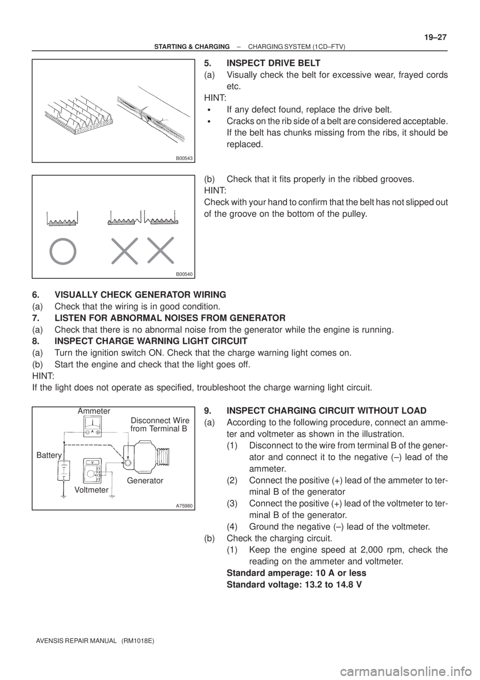
(a) According to the following procedure, connect an amme-
ter and voltmeter as shown in the illustration.
(1) Disconnect to the wire from terminal B of the gener-
ator and connect it to the negative (±) lead of the
ammeter.
(2) Connect the positive (+) lead of the ammeter to ter-
minal B of the generator
(3) Connect the positive (+) lead of the voltmeter to ter-
minal B of the generator.
(4) Ground the negative (±) lead of the voltmeter.
(b) Check the charging circuit.
(1) Keep the engine speed at 2,000 rpm, check the
reading on the ammeter and voltmeter.
Standard amperage: 10 A or less
Standard voltage: 13.2 to 14.8 V
Page 2479 of 5135
B00540
A75980
Disconnect Wire
from Terminal B
Generator
Voltmeter BatteryAmmeter
± STARTING & CHARGINGCHARGING SYSTEM (1AZ±FSE)
19±19
AVENSIS REPAIR MANUAL (RM1018E)
(b) Check that it fits properly in the ribbed grooves.
HINT:
Check with your hand to confirm that the belt has not slipped out
of the groove on the bottom of the pulley.
5. VISUALLY CHECK GENERATOR WIRING
(a) Check that the wiring is in good condition.
6. LISTEN FOR ABNORMAL NOISES FROM GENERATOR
(a) Check that there is no abnormal noise from the generator while the engine is running.
7. INSPECT CHARGE WARNING LIGHT CIRCUIT
(a) Turn the ignition switch ON. Check that the charge warning light comes on.
(b) Start the engine and check that the light goes off.
HINT:
If the light does not operate as specified, troubleshoot the charge warning light circuit.
8. INSPECT CHARGING CIRCUIT WITHOUT LOAD
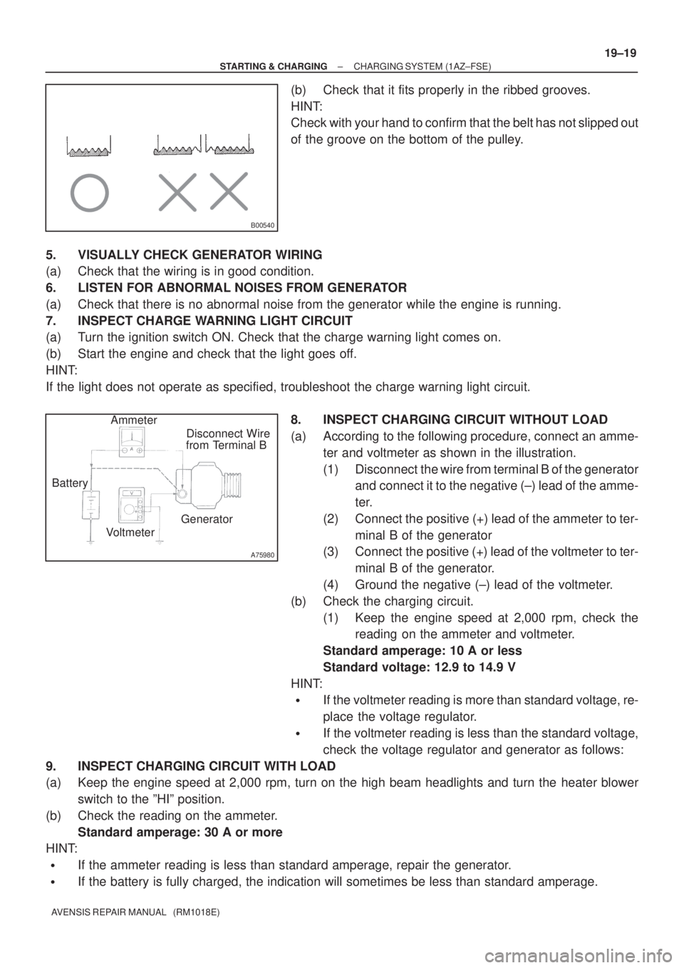
(a) According to the following procedure, connect an amme-
ter and voltmeter as shown in the illustration.
(1) Disconnect the wire from terminal B of the generator
and connect it to the negative (±) lead of the amme-
ter.
(2) Connect the positive (+) lead of the ammeter to ter-
minal B of the generator
(3) Connect the positive (+) lead of the voltmeter to ter-
minal B of the generator.
(4) Ground the negative (±) lead of the voltmeter.
(b) Check the charging circuit.
(1) Keep the engine speed at 2,000 rpm, check the
reading on the ammeter and voltmeter.
Standard amperage: 10 A or less
Standard voltage: 12.9 to 14.9 V
HINT:
�If the voltmeter reading is more than standard voltage, re-
place the voltage regulator.
�If the voltmeter reading is less than the standard voltage,
check the voltage regulator and generator as follows:
9. INSPECT CHARGING CIRCUIT WITH LOAD
(a) Keep the engine speed at 2,000 rpm, turn on the high beam headlights and turn the heater blower
switch to the ºHIº position.
(b) Check the reading on the ammeter.
Standard amperage: 30 A or more
HINT:
�If the ammeter reading is less than standard amperage, repair the generator.
�If the battery is fully charged, the indication will sometimes be less than standard amperage.
Page 2482 of 5135
B00540
A75980
Disconnect Wire
from Terminal B
Generator
Voltmeter BatteryAmmeter 19±16
± STARTING & CHARGINGCHARGING SYSTEM (1AZ±FE)
AVENSIS REPAIR MANUAL (RM1018E)
(b) Check that it fits properly in the ribbed grooves.
HINT:
Check with your hand to confirm that the belt has not slipped out
of the groove on the bottom of the pulley.
5. VISUALLY CHECK GENERATOR WIRING
(a) Check that the wiring is in good condition.
6. LISTEN FOR ABNORMAL NOISES FROM GENERATOR
(a) Check that there is no abnormal noise from the generator while the engine is running.
7. INSPECT CHARGE WARNING LIGHT CIRCUIT
(a) Turn the ignition switch ON. Check that the charge warning light comes on.
(b) Start the engine and check that the light goes off.
HINT:
If the light does not operate as specified, troubleshoot the charge warning light circuit.
8. INSPECT CHARGING CIRCUIT WITHOUT LOAD
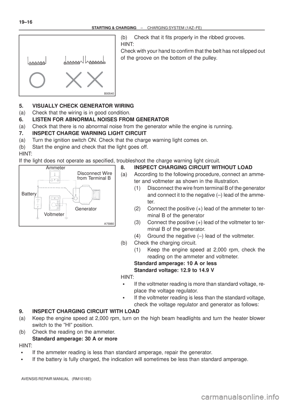
(a) According to the following procedure, connect an amme-
ter and voltmeter as shown in the illustration.
(1) Disconnect the wire from terminal B of the generator
and connect it to the negative (±) lead of the amme-
ter.
(2) Connect the positive (+) lead of the ammeter to ter-
minal B of the generator
(3) Connect the positive (+) lead of the voltmeter to ter-
minal B of the generator.
(4) Ground the negative (±) lead of the voltmeter.
(b) Check the charging circuit.
(1) Keep the engine speed at 2,000 rpm, check the
reading on the ammeter and voltmeter.
Standard amperage: 10 A or less
Standard voltage: 12.9 to 14.9 V
HINT:
�If the voltmeter reading is more than standard voltage, re-
place the voltage regulator.
�If the voltmeter reading is less than the standard voltage,
check the voltage regulator and generator as follows:
9. INSPECT CHARGING CIRCUIT WITH LOAD
(a) Keep the engine speed at 2,000 rpm, turn on the high beam headlights and turn the heater blower
switch to the ºHIº position.
(b) Check the reading on the ammeter.
Standard amperage: 30 A or more
HINT:
�If the ammeter reading is less than standard amperage, repair the generator.
�If the battery is fully charged, the indication will sometimes be less than standard amperage.
Page 2643 of 5135
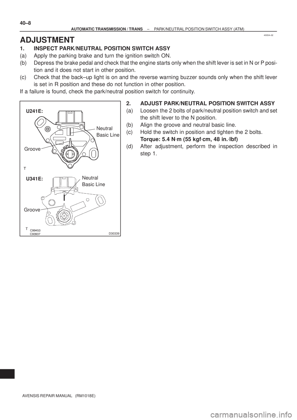
400DA±02
������������D30339
Neutral
Basic Line
Groove
Neutral
Basic Line
GrooveU241E:
U341E: 40±8
± AUTOMATIC TRANSMISSION / TRANSPARK/NEUTRAL POSITION SWITCH ASSY (ATM)
AVENSIS REPAIR MANUAL (RM1018E)
ADJUSTMENT
1. INSPECT PARK/NEUTRAL POSITION SWITCH ASSY
(a) Apply the parking brake and turn the ignition switch ON.
(b) Depress the brake pedal and check that the engine starts only when the shift lever is set in N or P posi-
tion and it does not start in other position.
(c) Check that the back±up light is on and the reverse warning buzzer sounds only when the shift lever
is set in R position and these do not function in other position.
If a failure is found, check the park/neutral position switch for continuity.
2. ADJUST PARK/NEUTRAL POSITION SWITCH ASSY
(a) Loosen the 2 bolts of park/neutral position switch and set
the shift lever to the N position.
(b) Align the groove and neutral basic line.
(c) Hold the switch in position and tighten the 2 bolts.
Torque: 5.4 N�m (55 kgf�cm, 48 in.�lbf)
(d) After adjustment, perform the inspection described in
step 1.
Page 2672 of 5135
±
BRAKE STEERING SENSOR
32±67
AVENSIS REPAIR MANUAL (RM1018E)
20.CONNECT BATTERY NEGATIVE TERMINAL (See page 60±1)
21.INSPECT SRS WARNING LIGHT (See page 05±1184)
22.INSPECT ABS WARNING LIGHT AND VSC WARNING LIGHT (See page 05±756)