Page 3112 of 5135

650SR±01
������7 8
9 654 3 2 1
10 11 12 13 14 15 16 17I33101
I35771
± LIGHTINGLIGHTING SYSTEM
65±9
AVENSIS REPAIR MANUAL (RM1018E)
INSPECTION
1. HEADLAMP DIMMER SWITCH ASSY
(a) Inspect light control switch continuity.
(1) Check that there is continuity between the terminals
at each switch position as shown in the chart.
Standard:
Switch operationTester connectionSpecified condition
OFF±No continuity
TAIL14 ± 16Continuity
HEAD13 ± 16 ± 14Continuity
(b) Inspect headlight dimmer switch continuity.
(1) Check that there is continuity between the terminals
at each switch position as shown in the chart.
Standard:
Switch operationTester connectionSpecified condition
FLASH7 ± 8 ± 16Continuity
LOW BEAM16 ± 17Continuity
HI BEAM7 ± 16Continuity
(c) Inspect turn signal switch continuity.
(1) Check that there is continuity between the terminals
at each switch position as shown in the chart.
Standard:
Switch operationTester connectionSpecified condition
Right turn2 ± 3Continuity
Neutral±No continuity
Left turn1 ± 2Continuity
(d) Inspect front fog light switch continuity.
(1) Check that there is continuity between the terminals
at each switch position as shown in the chart.
Standard:
Switch operationTester connectionSpecified condition
OFF±No continuity
Front fog switch ON10 ± 11Continuity
Rear fog switch ON10 ± 12Continuity
2. HAZARD WARNING SIGNAL SWITCH ASSY
(a) Check that there is continuity between the terminals at
each switch position as shown in the chart.
Standard:
Switch operationTester connectionSpecified condition
OFF1 ± 4No continuity
ON1 ± 4Continuity
Illumination circuit8 ± 9Continuity
Page 3171 of 5135
700TB±01
B67064
LHD Models
Defogger Wire
Liftback
Wagon
Defogger Wire
Defogger Wire
Hazard Warning Signal Switch Assy w/ Deicer:
FR DEICER Relay
Fuse Block Assy
w/ Deicer:
FR DIC Fuse
w/ Mirror Heater:
MIR HTR Fuse
Passenger Side R/B Assy
w/ Mirror Heater:
Outer Rear View Mirror Assy RH
w/ Mirror Heater:
Outer Rear View
Mirror Assy LH
Rear Window
Defogger Relay
70±46
± WINDSHIELD/WINDOWGLASS/MIRRORWINDOW DEFOGGER SYSTEM
AVENSIS REPAIR MANUAL (RM1018E)
WINDOW DEFOGGER SYSTEM
LOCATION
Page 3172 of 5135
B67246
RHD Models
Defogger Wire
Liftback
Wagon
Defogger Wire Defogger Wire
Hazard Warning Signal Switch Assy
Passenger Side R/B Assy
w/ Deicer:
FR DEICER Relay
Fuse Block Assy
w/ Deicer:
FR DIC Fuse w/ Mirror Heater:
Outer Rear View Mirror Assy RH
w/ Mirror Heater:
Outer Rear View Mirror Assy LH
w/ Mirror Heater:
MIR HTR Fuse
Rear Window
Defogger Relay
± WINDSHIELD/WINDOWGLASS/MIRRORWINDOW DEFOGGER SYSTEM
70±47
AVENSIS REPAIR MANUAL (RM1018E)
Page 3230 of 5135
71±20
±
INSTRUMENT PANEL/METER INSTRUMENT PANEL SUB±ASSY LOWER
AVENSIS REPAIR MANUAL (RM1018E)
46.ADJUST SPIRAL CABLE SUB±ASSY (See page 60±26)
47.INSTALL STEERING WHEEL ASSY (See page 50±9)
48.INSTALL HORN BUTTON ASSY (See page 60±17)
49.INSPECT HORN BUTTON ASSY (See page 60±11)
50.INSPECT SRS WARNING LIGHT (See page 05±1184)
Page 3236 of 5135

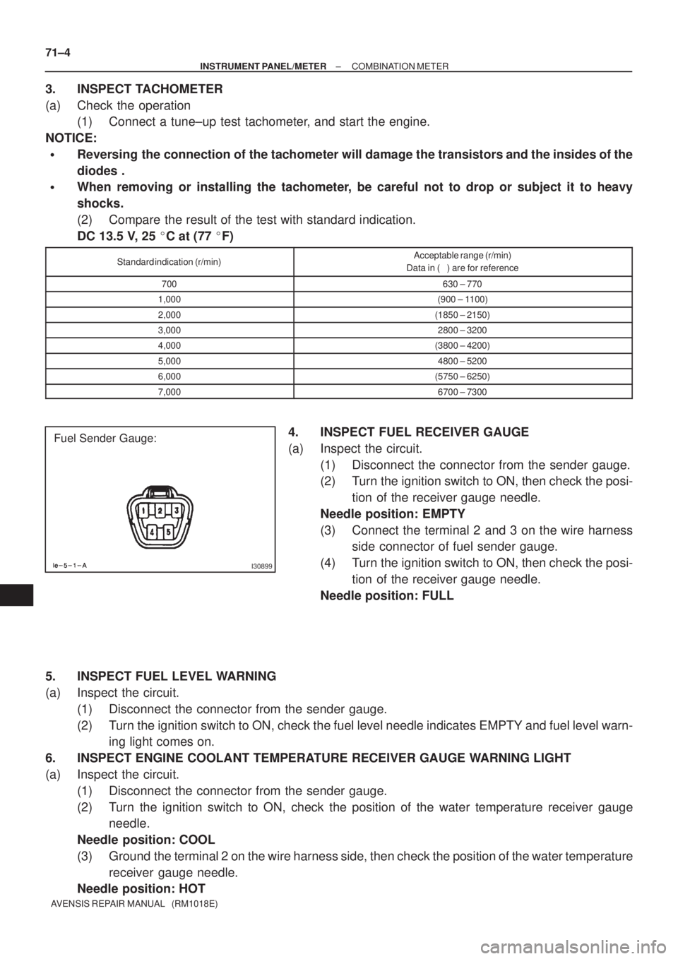
I30899
Fuel Sender Gauge: 71±4
± INSTRUMENT PANEL/METERCOMBINATION METER
AVENSIS REPAIR MANUAL (RM1018E)
3. INSPECT TACHOMETER
(a) Check the operation
(1) Connect a tune±up test tachometer, and start the engine.
NOTICE:
�Reversing the connection of the tachometer will damage the transistors and the insides of the
diodes .
�When removing or installing the tachometer, be careful not to drop or subject it to heavy
shocks.
(2) Compare the result of the test with standard indication.
DC 13.5 V, 25 �C at (77 �F)
Standard indication (r/min)Acceptable range (r/min)
Data in ( ) are for reference
700630 ± 770
1,000(900 ± 1100)
2,000(1850 ± 2150)
3,0002800 ± 3200
4,000(3800 ± 4200)
5,0004800 ± 5200
6,000(5750 ± 6250)
7,0006700 ± 7300
4. INSPECT FUEL RECEIVER GAUGE
(a) Inspect the circuit.
(1) Disconnect the connector from the sender gauge.
(2) Turn the ignition switch to ON, then check the posi-
tion of the receiver gauge needle.
Needle position: EMPTY
(3) Connect the terminal 2 and 3 on the wire harness
side connector of fuel sender gauge.
(4) Turn the ignition switch to ON, then check the posi-
tion of the receiver gauge needle.
Needle position: FULL
5. INSPECT FUEL LEVEL WARNING
(a) Inspect the circuit.
(1) Disconnect the connector from the sender gauge.
(2) Turn the ignition switch to ON, check the fuel level needle indicates EMPTY and fuel level warn-
ing light comes on.
6. INSPECT ENGINE COOLANT TEMPERATURE RECEIVER GAUGE WARNING LIGHT
(a) Inspect the circuit.
(1) Disconnect the connector from the sender gauge.
(2) Turn the ignition switch to ON, check the position of the water temperature receiver gauge
needle.
Needle position: COOL
(3) Ground the terminal 2 on the wire harness side, then check the position of the water temperature
receiver gauge needle.
Needle position: HOT
Page 3237 of 5135

IG
SPEED
BKL SW
(D±seat)
BKL SW
(P seat)
WRN LAMP
BUZZERON
OFF
15km/h
0
BELT ON
BELT OFF
LVL1
LVL2 BELT ON
BELT OFF
ON
OFF OFF
30s
90s30s
90s
± INSTRUMENT PANEL/METERCOMBINATION METER
71±5
AVENSIS REPAIR MANUAL (RM1018E)
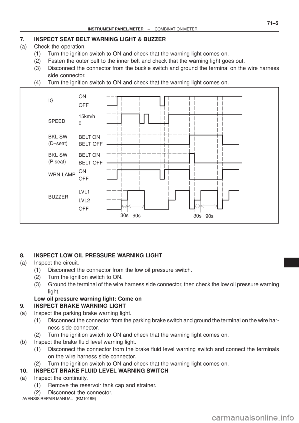
7. INSPECT SEAT BELT WARNING LIGHT & BUZZER
(a) Check the operation.
(1) Turn the ignition switch to ON and check that the warning light comes on.
(2) Fasten the outer belt to the inner belt and check that the warning light goes out.
(3) Disconnect the connector from the buckle switch and ground the terminal on the wire harness
side connector.
(4) Turn the ignition switch to ON and check that the warning light comes on.
8. INSPECT LOW OIL PRESSURE WARNING LIGHT
(a) Inspect the circuit.
(1) Disconnect the connector from the low oil pressure switch.
(2) Turn the ignition switch to ON.
(3) Ground the terminal of the wire harness side connector, then check the low oil pressure warning
light.
Low oil pressure warning light: Come on
9. INSPECT BRAKE WARNING LIGHT
(a) Inspect the parking brake warning light.
(1) Disconnect the connector from the parking brake switch and ground the terminal on the wire har-
ness side connector.
(2) Turn the ignition switch to ON and check that the warning light comes on.
(b) Inspect the brake fluid level warning light.
(1) Disconnect the connector from the brake fluid level warning switch and connect the terminals
on the wire harness side connector.
(2) Turn the ignition switch to ON and check that the warning light comes on.
10. INSPECT BRAKE FLUID LEVEL WARNING SWITCH
(a) Inspect the continuity.
(1) Remove the reservoir tank cap and strainer.
(2) Disconnect the connector.
Page 3238 of 5135
71±6
±
INSTRUMENT PANEL/METER COMBINATION METER
AVENSIS REPAIR MANUAL (RM1018E)
(3)Check that the continuity exists between the terminals.
Float up (switch off): No continuity
(4)Use a syphon, etc., to take fluid out of the reservoir tank.
(5)Check that the continuity exists between the terminals.
Float down (switch on): Continuity
(6)Pour the fluid back in the reservoir tank.
(7)Reconnect the connector.
(8)Check that the buzzer stop after about 4 to 8 seconds.
11.INSPECT KEY REMINDER WARNING BUZZER
(a)Check warning buzzer function. (1)Turn the ignition switch ON and check that the key reminder warning sounds i\
f the ignition keyis insert the key cylinder and front driver side door is opened (See Page 05±1586).
Page 3239 of 5135

710CM±02
±
INSTRUMENT PANEL/METER COMBINATION METER
71±1
AVENSIS REPAIR MANUAL (RM1018E)
COMBINATION METER
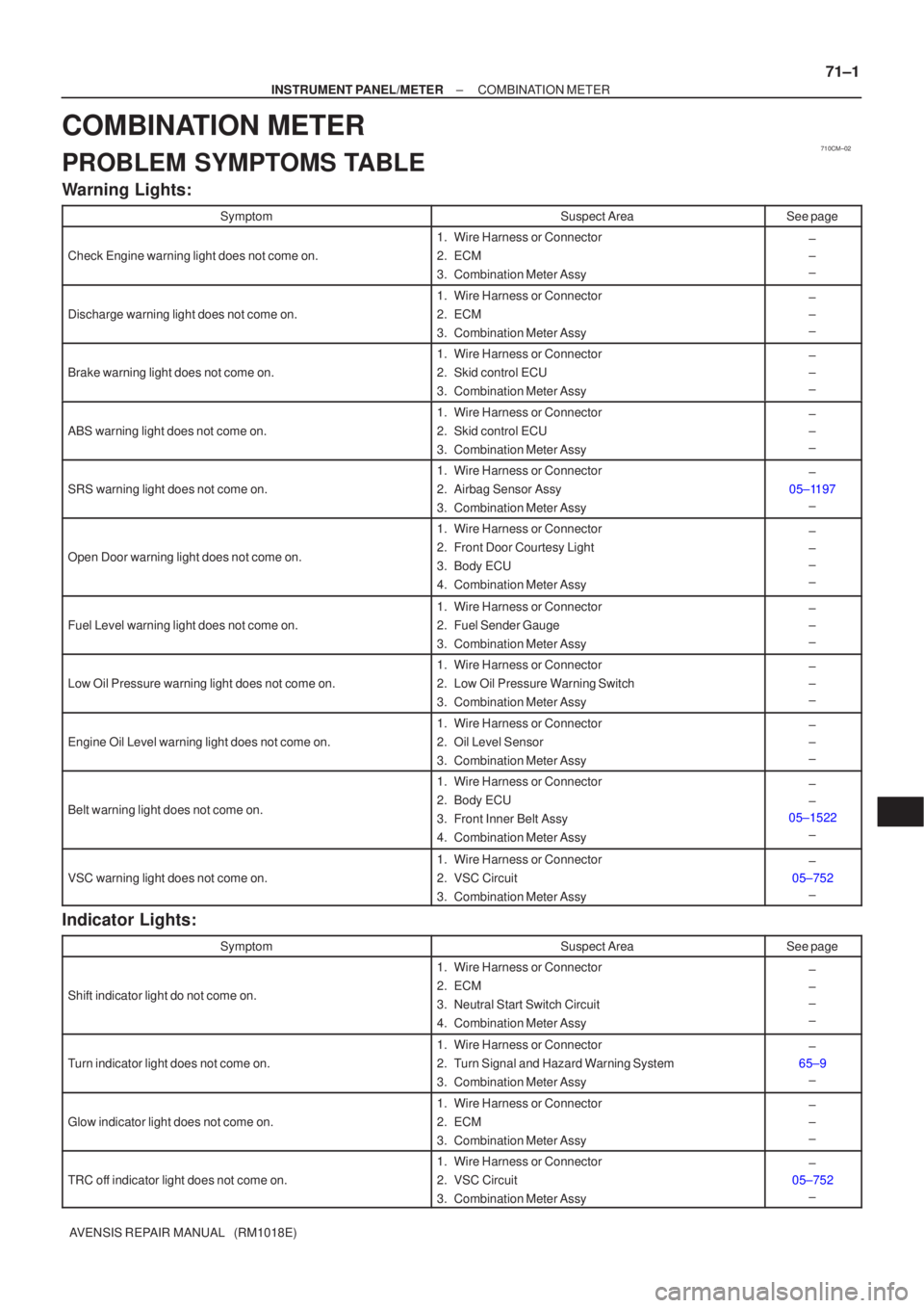
PROBLEM SYMPTOMS TABLE
Warning Lights:
SymptomSuspect AreaSee page
Check Engine warning light does not come on.
1.Wire Harness or Connector
2.ECM
3.Combination Meter Assy±
±
±
Discharge warning light does not come on.
1.Wire Harness or Connector
2.ECM
3.Combination Meter Assy±
±
±
Brake warning light does not come on.
1.Wire Harness or Connector
2.Skid control ECU
3.Combination Meter Assy±
±
±
ABS warning light does not come on.
1.Wire Harness or Connector
2.Skid control ECU
3.Combination Meter Assy±
±
±
SRS warning light does not come on.
1.Wire Harness or Connector
2.Airbag Sensor Assy
3.Combination Meter Assy±
05±1197 ±
Open Door warning light does not come on.
1.Wire Harness or Connector
2.Front Door Courtesy Light
3.Body ECU
4.Combination Meter Assy±
±
±
±
Fuel Level warning light does not come on.
1.Wire Harness or Connector
2.Fuel Sender Gauge
3.Combination Meter Assy±
±
±
Low Oil Pressure warning light does not come on.
1.Wire Harness or Connector
2.Low Oil Pressure Warning Switch
3.Combination Meter Assy±
±
±
Engine Oil Level warning light does not come on.
1.Wire Harness or Connector
2.Oil Level Sensor
3.Combination Meter Assy±
±
±
Belt warning light does not come on.
1.Wire Harness or Connector
2.Body ECU
3.Front Inner Belt Assy
4.Combination Meter Assy±
±
05±1522
±
VSC warning light does not come on.
1.Wire Harness or Connector
2.VSC Circuit
3.Combination Meter Assy±
05±752 ±
Indicator Lights:
SymptomSuspect AreaSee page
Shift indicator light do not come on.
1. Wire Harness or Connector
2. ECM
3. Neutral Start Switch Circuit
4. Combination Meter Assy±
±
±
±
Turn indicator light does not come on.
1. Wire Harness or Connector
2. Turn Signal and Hazard Warning System
3. Combination Meter Assy±
65±9 ±
Glow indicator light does not come on.
1. Wire Harness or Connector
2. ECM
3. Combination Meter Assy±
±
±
TRC off indicator light does not come on.
1. Wire Harness or Connector
2. VSC Circuit
3. Combination Meter Assy±
05±752 ±