Page 2735 of 5135
D28034Shift Lock Release Link
C63997
40±76
±
AUTOMATIC TRANSMISSION / TRANS FLOOR SHIFT PARKING LOCK CABLE ASSY
AVENSIS REPAIR MANUAL (RM1018E)
(h) Apply MP grease to the shift lock release link.
(i) Insert the lever pin into the hole in the cable end.
(j) Lock the lock key.
HINT:
At this time, the shift lever should be in the P position and the
ignition key should be set to Lock.
14.INSTALL INSTRUMENT PANEL AIR BAG ASSY (See page 60±29)
15.INSPECT INSTRUMENT PANEL AIR BAG ASSY (See page 60±29)
16.INSPECT SRS WARNING LIGHT (See page 05±1184)
17.CHECK KEY INTERLOCK OPERATION (See page 40±59)
Page 2739 of 5135
±
AUTOMATIC TRANSMISSION / TRANS TRANSMISSION CONTROL CABLE ASSY
40±73
AVENSIS REPAIR MANUAL (RM1018E)
7. INSTALL INSTRUMENT PANEL SUB±ASSY UPPER W/INSTR PNL PASS L/DOOR AIR BAG ASSY
(See page 71±11)
8.ADJUST SPIRAL CABLE SUB±ASSY (See page 60±26)
9.INSTALL STEERING WHEEL ASSY (See page 50±9)
10.INSTALL HORN BUTTON ASSY (See page 60±17)
11.INSTALL EXHAUST PIPE ASSY FRONT (1ZZ±FE ENGINE TYPE) (See page 15±2)
12.INSTALL EXHAUST PIPE ASSY FRONT (1AZ±FE/1AZ±FSE ENGINE TYPE) (See page 15±7)
13.INSPECT HORN BUTTON ASSY (See page 60±17)
14.INSPECT SRS WARNING LIGHT (See page 05±1184)
15. CHECK FOR EXHAUST GAS LEAKS
16.ADJUST SHIFT LEVER POSITION (See page 40±69)
17.INSPECT SHIFT LEVER POSITION (See page 40±69)
18.CHARGE REFRIGERANT (See page 55±38)
SST 07110±58060 (07117±58060, 07117±58070, 07117±58080, 07117±58090, 07117±78050, 07117±88060, 07117±88070, 07117±88080)
19.INSPECT LEAKAGE OF REFRIGERANT (See page 55±38)
Page 2803 of 5135
50±22
±
STEERING COLUMN POWER STEERING ECU ASSY
AVENSIS REPAIR MANUAL (RM1018E)
NOTICE:
�When reusing the clamp, check that there is no dam-
age on it.
�When reinstalling the wire harness, make sure there
is no twist in the harness or with other wire harness.
18. CONNECT BATTERY NEGATIVE TERMINAL
19.INSPECT SRS WARNING LIGHT (See page 05±1184)
20.PERFORM CALIBRATION OF TORQUE SENSOR ZERO POINT (See page 05±1045)
Page 2810 of 5135

38. REMOVE UN±LOCK WARNING SWITCH ASSY
(a) Slide the unlock warning switch assy out of")
F44798
F44799
F44793Matchmarks
±
STEERING COLUMN STEERING COLUMN ASSY
50±15
AVENSIS REPAIR MANUAL (RM1018E)
38. REMOVE UN±LOCK WARNING SWITCH ASSY
(a) Slide the unlock warning switch assy out of the steering column upper br\
acket.
39. REMOVE IGNITION OR STARTER SWITCH ASSY
(a) Remove the 2 screws and ignition or starter switch assy.
40. INSTALL IGNITION OR STARTER SWITCH ASSY
(a) Install the ignition or starter switch assy to the steering column upper w/swit\
ch bracket assy with the
2 screws.
41. INSTALL UN±LOCK WARNING SWITCH ASSY
(a) Install the un±lock warning switch assy.
(b) Connect the un±lock warning switch assy connector to the ignition or \
starter switch assy.
42. INSTALL IGNITION SWITCH LOCK CYLINDER ASSY
(a) Make sure of the ignition switch lock cylinder assy at the ACC position.\
(b) Install the ignition switch lock cylinder assy.
43. INSPECT STEERING LOCK OPERATION
(a) Check that the steering lock mechanism is activated when removing the ke\
y.
(b) Check that the steering lock mechanism is deactivated when inserting the\
key and turning it to ACC position.
44. INSTALL TRANSPONDER KEY AMPLIFIER
(a) Align the transponder key amplifier with the installationposition of the upper bracket with the amplifier inclined.
(b) Push the transponder key amplifier up and connect it to the upper bracket.
NOTICE:
Take care not to push the amplifier up with excessive force
to prevent it from being damaged.
45. INSTALL STEERING COLUMN UPPER W/SWITCH BRACKET ASSY
(a) Temporarily install the steering column upper with switch bracket assy and steering column upper clamp with 2 new
tapered±head bolts.
(b) Tighten the 2 tapared±head bolts until the bolt heads break off.
46. INSTALL STEERING SLIDING YOKE SUB±ASSY (RHD STEERING POSITION TYPE)
(a) W/VSC:
Install the steering sensor (See page 32±65).
(b) Align matchmarks on the steering sliding yoke and steer- ing main shaft.
(c) Oil Pressure Power Steering
(1) Install the steering sliding yoke with the bolt.
Torque: 28 N �m (286 kgf �cm, 21 ft �lbf)
Page 2814 of 5135

54.INSTALL INSTRUMENT PANEL AIR BAG ASSY (See page 60±54)
55. INSTALL COLUMN")
F44800
Marks
F44801
Torx ScrewScrew Case
±
STEERING COLUMN STEERING COLUMN ASSY
50±19
AVENSIS REPAIR MANUAL (RM1018E)
54.INSTALL INSTRUMENT PANEL AIR BAG ASSY (See page 60±54)
55. INSTALL COLUMN HOLE COVER SILENCER SHEET
56. PLACE FRONT WHEELS FACING STRAIGHT AHEAD
57.INSTALL SPIRAL CABLE SUB±ASSY (See page 60±26)
58. CENTER SPIRAL CABLE
(a) Check that the front wheels are facing straight ahead.
(b) Turn the cable counterclockwise by hand until it becomesharder to turn.
(c) Then rotate the cable clockwise about 2.5 turns to align the marks.
HINT:
The cable will rotate about 2.5 turns to either left or right of the
center.
59. INSTALL STEERING WHEEL ASSY
(a) Align matchmarks on the steering wheel and main shaft assembly.
(b) Install the steering wheel set nut. Torque: 50 N´m (510 kgf´cm, 37 ft´lbf)
(c) Connect the connector.
60. INSTALL HORN BUTTON ASSY
NOTICE:
�Never use airbag parts from another vehicle. When
replacing parts, replace with new ones.
�Make sure the horn button assy is installed with the
specified torque.
�If the horn button assy has been dropped, or there are
cracks, dents or other defects in the case or connec-
tor, replace the horn button assy with a new one.
�When installing the horn button assy, take care that
the wirings do not interfere with other parts and that
they are not pinched between other parts.
(a) Connect the terminal.
(b) Connect the airbag connector.
(c) Install the steering horn button assy after confirming that the circumference groove of the torx screws is caught on
the screw case.
(d) Using a torx socket wrench, torque the 2 screws. Torque: 8.8 N´m (90 kgf´cm, 78 in.´lbf)
61. STEERING WHEEL CENTER POINT
62. CONNECT BATTERY NEGATIVE TERMINAL
63.INSPECT SRS WARNING LIGHT(See page 05±1184)
64. PERFORM CALIBRATION OF TORQUE SENSOR ZERO POINT (ELECTRIC POWER STEERING) (See page 05±1045)
Page 2816 of 5135
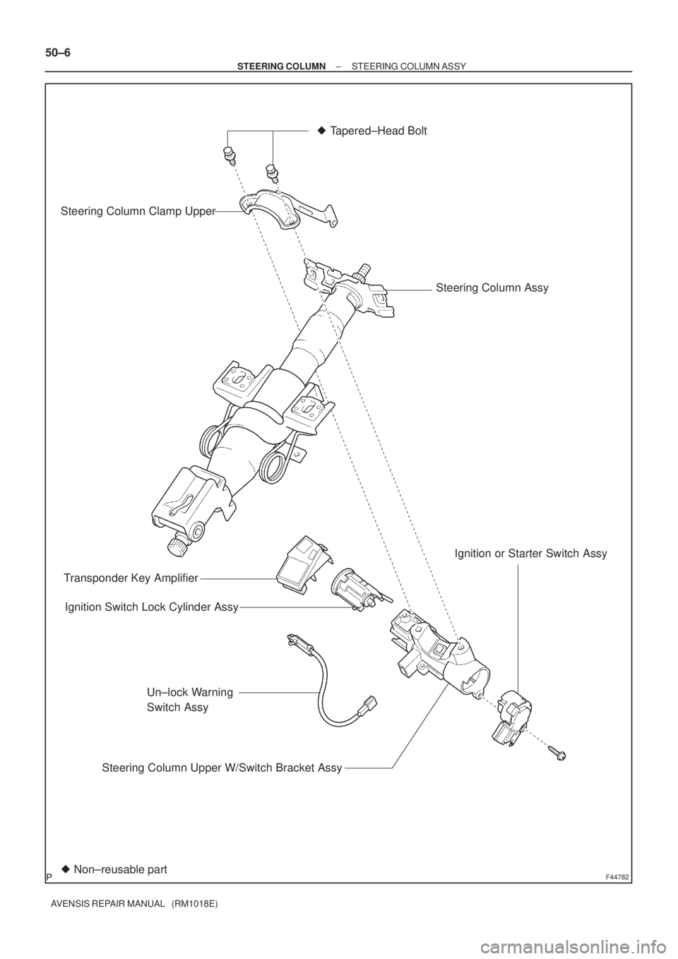
F44782
Transponder Key Amplifier� Tapered±Head Bolt
Steering Column Clamp Upper
Ignition or Starter Switch Assy
Un±lock Warning
Switch Assy
Steering Column Upper W/Switch Bracket Assy Ignition Switch Lock Cylinder Assy
Non±reusable part �
Steering Column Assy
50±6
± STEERING COLUMNSTEERING COLUMN ASSY
AVENSIS REPAIR MANUAL (RM1018E)
Page 2818 of 5135
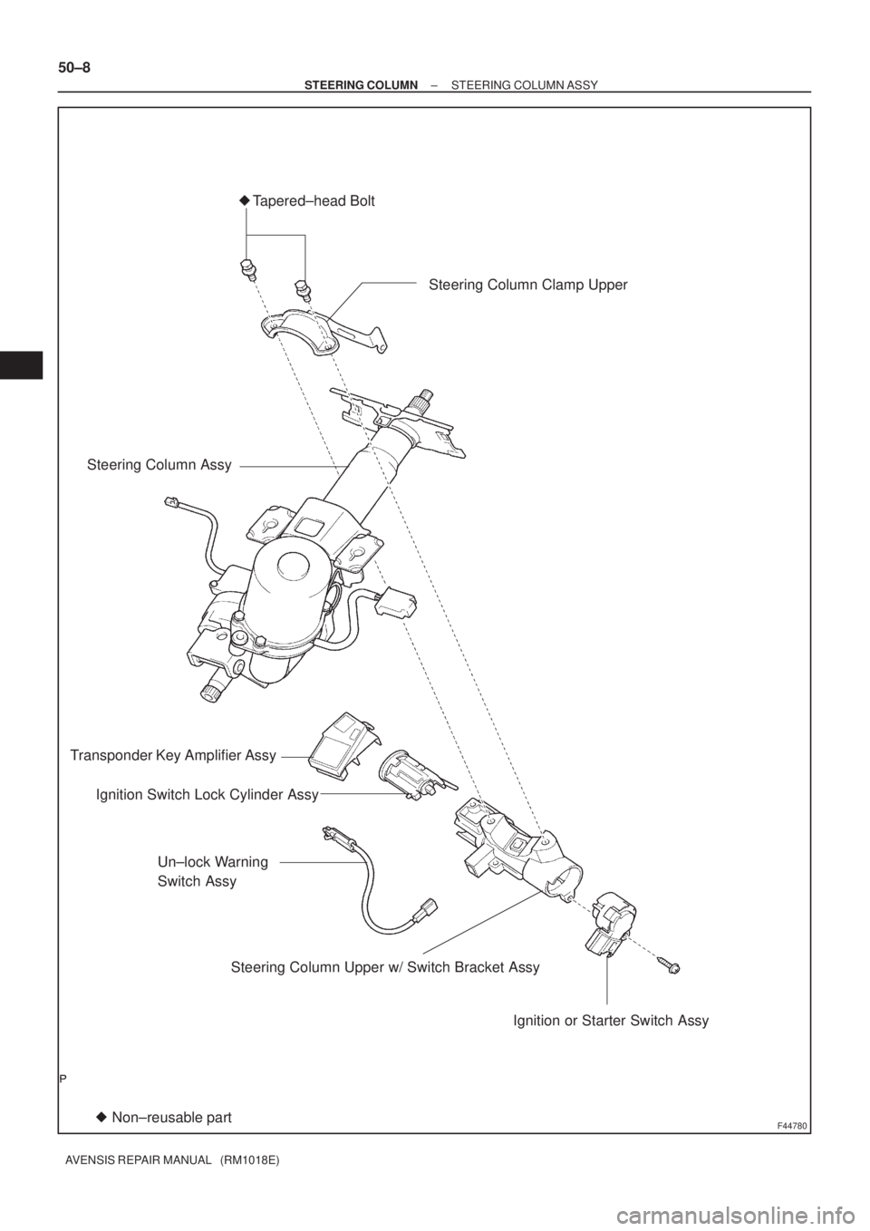
F44780
Transponder Key Amplifier AssyTapered±head Bolt
Ignition or Starter Switch Assy Steering Column Assy�
Non±reusable part �Steering Column Clamp Upper
Un±lock Warning
Switch Assy
Steering Column Upper w/ Switch Bracket Assy Ignition Switch Lock Cylinder Assy
50±8
± STEERING COLUMNSTEERING COLUMN ASSY
AVENSIS REPAIR MANUAL (RM1018E)
Page 2968 of 5135

REPLACEMENT
1.PRECAUTION (Se")
600JY±01
H42642
H42643
H42644
Hook
Airbag DoorHook
Front
±
SUPPLEMENTAL RESTRAINT SYSTEM INSTRUMENT PANEL PASSENGER AIR BAG ASSY
60±29
AVENSIS REPAIR MANUAL (RM1018E)
REPLACEMENT
1.PRECAUTION (See page 60±1)
2.DISCONNECT BATTERY NEGATIVE TERMINAL (See page 60±1)
3.REMOVE GLOVE COMPARTMENT DOOR ASSY (See page 71±11)
4. DISCONNECT PASSENGER AIRBAG CONNECTOR
(a) Remove the passenger airbag connector clip.
(b) Disconnect the passenger airbag connector.
5. REMOVE INSTRUMENT PANEL SUB±ASSY UPPER W/INSTR PNL PASS L/DOOR AIR BAG ASSY (See page 71±11)
6. REMOVE INSTRUMENT PANEL PASSENGER AIRBAG ASSY
(a) Remove the 2 screws.
(b) Release the rear side wall of the airbag door from the hook by slightly deflecting it and roll the instrument panel
passenger airbag assy forward.
(c) Release the front side wall of the airbag door from the oth-
er hook and remove the instrument panel passenger air-
bag assy.
7. INSTALL INSTRUMENT PANEL PASSENGER AIR BAG ASSY
8.INSPECT INSTRUMENT PANEL PASSENGER AIR BAG ASSY (See page 60±11)
9. INSTALL INSTRUMENT PANEL SUB±ASSY UPPER W/INSTR PNL PASS L/DOOR AIR BAG ASSY (See page 71±11)
10.INSPECT SRS WARNING LIGHT (See page 05±1184)

(h) Apply MP grease to the shift lock release link.")

7. INSTALL INSTRUMENT PANEL SUB±ASSY UPPER W/INSTR PNL PASS L/DOOR AIR BAG ASSY
(See page 71")