Page 1624 of 5135
B65427
Unlock
Lock LHD models
B65428
UnlockLock LHD models 05±1552
± DIAGNOSTICSPOWER DOOR LOCK CONTROL SYSTEM
AVENSIS REPAIR MANUAL (RM1018E)
6 INSPECT DRIVER DOOR LOCK
(a) LHD models:
Apply battery voltage to the door lock motor and check
operation.
Standard:
Measurement ConditionSpecified Condition
Battery positive (+) � Terminal 4
Battery negative (±) � Terminal 1Lock
Battery positive (+) � Terminal 1
Battery negative (±) � Terminal 4Unlock
(b) LHD models:
Inspect the door lock and unlock switch resistance.
Standard:
Tester ConnectionDoor Lock PositionSpecified Condition
7 ± 9LockBelow 1 �
7 ± 9, 7 ± 10OFF10 k�or higher
7 ± 10UnlockBelow 1 �
(c) LHD models:
Inspect the position switch resistance.
Standard:
Tester ConnectionDoor Lock PositionSpecified Condition
78Lock10 k�or higher7 ± 8UnlockBelow 1 �
Page 1625 of 5135
B65429
Unlock
Lock RHD models
B65430
Unlock
LockRHD models
± DIAGNOSTICSPOWER DOOR LOCK CONTROL SYSTEM
05±1553
AVENSIS REPAIR MANUAL (RM1018E)
(d) RHD models:
Apply battery voltage to the door lock motor and check
operation.
Standard:
Measurement ConditionSpecified Condition
Battery positive (+) � Terminal 4
Battery negative (±) � Terminal 1Lock
Battery positive (+) � Terminal 1
Battery negative (±) � Terminal 4Unlock
(e) RHD models:
Inspect the door lock and unlock switch resistance.
Standard:
Tester ConnectionDoor Lock PositionSpecified Condition
6 ± 8LockBelow 1 �
6 ± 8, 5 ± 8OFF10 k�or higher
5 ± 8UnlockBelow 1 �
(f) RHD models:
Inspect the position switch resistance.
Standard:
Tester ConnectionDoor Lock PositionSpecified Condition
78Lock10 k�or higher7 ± 8UnlockBelow 1 �
NG REPLACE DRIVER DOOR LOCK
OK
Page 1672 of 5135
B67698
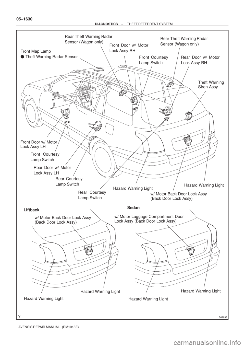
Front Map Lamp
� Theft Warning Radar Sensor
Hazard Warning LightHazard Warning Light
Hazard Warning Light
Hazard Warning LightHazard Warning Light
Hazard Warning Light
LiftbackSedanFront Courtesy
Lamp Switch Front Door w/ Motor
Lock Assy RH
Front Door w/ Motor
Lock Assy LH
Front Courtesy
Lamp Switch
w/ Motor Back Door Lock Assy
(Back Door Lock Assy)Theft Warning
Siren Assy
w/ Motor Luggage Compartment Door
Lock Assy (Back Door Lock Assy)
Rear Courtesy
Lamp Switch Rear Door w/ Motor
Lock Assy LHRear Theft Warning Radar
Sensor (Wagon only)
Rear Theft Warning Radar
Sensor (Wagon only)
Rear Door w/ Motor
Lock Assy RH
Rear Courtesy
Lamp Switch
w/ Motor Back Door Lock Assy
(Back Door Lock Assy) 05±1630
± DIAGNOSTICSTHEFT DETERRENT SYSTEM
AVENSIS REPAIR MANUAL (RM1018E)
Page 1809 of 5135

RESISTANCE k�
(±4) (32) (80) (140)(104) (212)(176)
A56275
VG
E2G
THA +B E2 Air
A31135
10±56
± ENGINE CONTROL SY")
100F0±02
321 4 5
±20
020 40 60
80100 0.1 0.2 0.3 0.51 235 1020 30
TEMPERATURE�C(�F)
RESISTANCE k�
(±4) (32) (80) (140)(104) (212)(176)
A56275
VG
E2G
THA +B E2 Air
A31135
10±56
± ENGINE CONTROL SYSTEMECD SYSTEM (1CD±FTV)
AVENSIS REPAIR MANUAL (RM1018E)
INSPECTION
1. INSPECT MASS AIR FLOW METER
(a) Output voltage inspection.
(1) Apply battery voltage across terminals 3 (+B) and 4
(E2G)
(2) Using a voltmeter, connect the positive (+) tester
probe to terminal VG, and negative (±) tester probe
to terminal E2G.
(3) Blow air into the air flow meter, and check that the
voltage fluctuates.
(b) Resistance inspection.
(1) Using an ohmmeter, measure the resistance be-
tween terminals 2 (THA) and 1 (E2).
Resistance:
±20�C (±4�F) 12.5 to 16.9 k�
20�C (68�F) 2.19 to 2.67 k�
60�C (140�F) 0.50 to 0.68 k�
2. INSPECT INTAKE SHUTTER ASSY
(a) Resistance inspection (Throttle control motor)
(1) Using an ohmmeter, measure the resistance be-
tween terminals.
Resistance:
TerminalsTemperatureResistance
2 ± 1, 3at 20�C (68�F)18 to 22 k�
5 ± 4, 6at 20�C (68�F)18 to 22 k�
Page 1813 of 5135

AVENSIS REPAIR MANUAL (RM1018E)
ECD SYSTEM(1CD±FTV)
ON±VEHICLE INSPECTION
1.INSPECTMASS AIR FLOW METER
(a)If")
100EZ±02
A75903
Air
A53763
VG
EVG
10±54
±
ENGINE CONTROL SYSTEM ECD SYSTEM(1CD±FTV)
AVENSIS REPAIR MANUAL (RM1018E)
ECD SYSTEM(1CD±FTV)
ON±VEHICLE INSPECTION
1.INSPECTMASS AIR FLOW METER
(a)If you have hand±held tester: Inspect for operation
(1)Connect the hand±held tester to the DLC3.
(2)Turn the ignition switch ON.
(3)Blow air into the MAF meter, and check that the airflow fluctuates (MAF ) of the CURRENT DATA
shown the standard value.
If operation is not as specified, check the MAF meter (See page
10±56), wiring and ECM.
(b)If you have no hand±held tester: Inspect for operation
(1)Turn the ignition switch ON.
(2)Connect the positive tester probe of the voltmeterto the terminal VG of the ECM. and the negative tes-
ter probe of the voltmeter to the terminal EVG of the
ECM.
(3)Blow air into the MAF meter, and check that the volt- age fluctuates.
If operation is not as specified, check the MAF meter (See page
10±56), wiring and ECM.
2.INSPECT INTAKE SHUTTER
(a)Inspect the throttle control motor for operating sound. (1)Turn the ignition switch ON.
(2)When turning the accelerator pedal position sensor lever, check the running sound of the motor.
Also, check that there is no friction sound.
If operation is not as specified, check the throttle control motor (See page 10±56), wiring and ECM.
(b)Inspect the throttle position sensor. (1)Connect the hand±held tester to the DLC3.
(2)Turn the ignition switch ON.
(3)When turning the accelerator pedal position sensor lever to the full±\
open position, check thatthe throttle valve opening percentage (THROTTLE POS) of the CURRENT DATA shown the
standard value.
Standard throttle valve opening percentage:
60 % or more
If operation is not as specified, check that the accelerator pedal positio\
n sensor (See page 10±56), wiring
and ECM.
If you have no hand±held tester, measure voltage between terminals (LU+A ± LU±A, LU+B ± LU±\
B) of the
ECM connector (See page 05±549).
Page 1818 of 5135
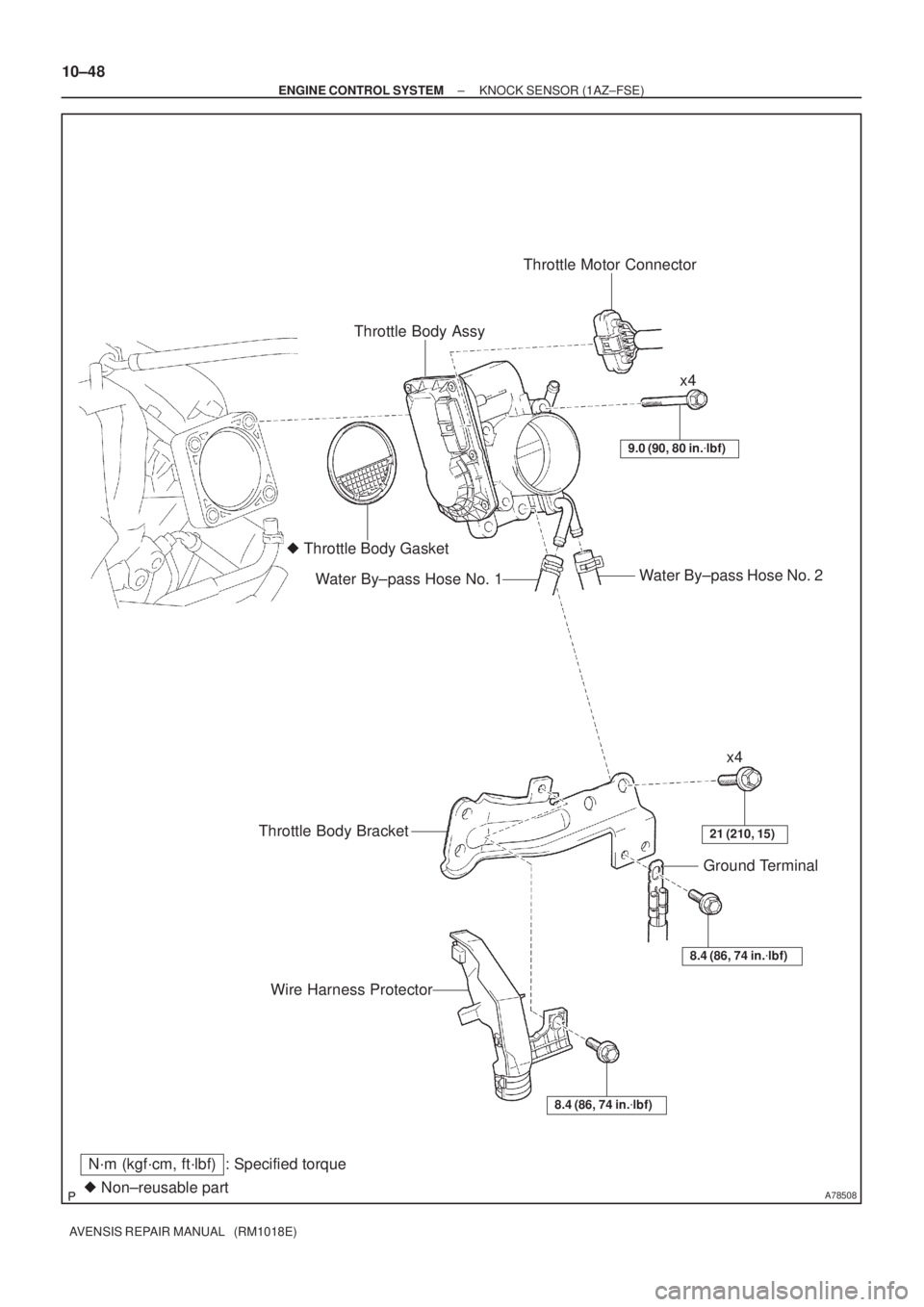
A78508� Non±reusable part
N´m (kgf´cm, ft´lbf) : Specified torqueThrottle Body AssyThrottle Motor Connector
� Throttle Body Gasket
Water By±pass Hose No. 2
Water By±pass Hose No. 1
9.0 (90, 80 in.�lbf)
x4
x4
21 (210, 15)Throttle Body Bracket
8.4 (86, 74 in.�lbf)
Ground Terminal
Wire Harness Protector
8.4 (86, 74 in.�lbf)
10±48
± ENGINE CONTROL SYSTEMKNOCK SENSOR (1AZ±FSE)
AVENSIS REPAIR MANUAL (RM1018E)
Page 1823 of 5135

A78512
(d)
A78513
(g)
(h)
±
ENGINE CONTROL SYSTEM THROTTLE BODY ASSY(1AZ±FSE)
10±45
AVENSIS REPAIR MANUAL (RM1018E)
(b)Remove the bolt, and then remove the ground terminal.
(c)Remove t")
A78511
(b)
A78512
(d)
A78513
(g)
(h)
±
ENGINE CONTROL SYSTEM THROTTLE BODY ASSY(1AZ±FSE)
10±45
AVENSIS REPAIR MANUAL (RM1018E)
(b)Remove the bolt, and then remove the ground terminal.
(c)Remove the 4 bolts, and then remove the throttle body
bracket.
(d)Disconnect the throttle motor connector.
(e)Remove the 4 bolts, and then remove the throttle body.
(f)Remove the gasket from the intake manifold.
(g)Disconnect the water by±pass hose No. 1.
(h)Disconnect the water by±pass hose No. 2.
7.INSTALL THROTTLE BODY ASSY
(a)Connect the water by±pass hose No. 2.
(b)Connect the water by±pass hose No. 1.
(c)Install a new gasket to the intake manifold.
(d)Install the throttle body with the 4 bolts. Torque: 9.0 N �m (90 kgf �cm, 80 in. �lbf)
(e)Connect the throttle motor connector.
(f)Install the throttle body bracket with the 4 bolts. Torque: 21 N �m (210 kgf �cm, 15 ft �lbf)
(g)Install the ground terminal with the bolt. Torque: 8.4 N �m (86 kgf �cm, 74 in. �lbf)
(h)Install the wire harness protector with the bolt. Torque: 8.4 N �m (86 kgf �cm, 74 in. �lbf)
8.INSTALL AIR CLEANER CAP SUB±ASSY Torque: 1.5 N �m (15 kgf �cm, 13 in. �lbf)
9.INSTALL ENGINE COVER SUB±ASSY NO.1 Torque: 7.0 N �m (71 kgf �cm, 62 in. �lbf)
10.ADD ENGINE COOLANT (See page 16±31)
11.CHECK FOR ENGINE COOLANT LEAKS (See page 16±25)
12. INSTALL ENGINE ROOM COVER SIDE
Page 1826 of 5135
A78508� Non±reusable part
N´m (kgf´cm, ft´lbf) : Specified torqueThrottle Body AssyThrottle Motor Connector
� Throttle Body Gasket
Water By±pass Hose No. 2
Water By±pass Hose No. 1
9.0 (90, 80 in.�lbf)
x4
x4
21 (210, 15)Throttle Body Bracket
8.4 (86, 74 in.�lbf)
Ground Terminal
Wire Harness Protector
8.4 (86, 74 in.�lbf)
± ENGINE CONTROL SYSTEMTHROTTLE BODY ASSY (1AZ±FSE)
10±43
AVENSIS REPAIR MANUAL (RM1018E)

6 INSPECT DRIVER DOOR LOCK
(a) LHD models:
Apply batt")

(d) RHD models:
Apply battery voltage to the door loc")