Page 1831 of 5135

AVENSIS REPAIR MANUAL (RM1018E)
2.INSPECT POWER STEERING OIL PRESSURE SEN- SOR
(a)Using a voltmeter, measure the voltage between ter")
A53763
E2PSW
10±38
±
ENGINE CONTROL SYSTEM SFI SYSTEM(1AZ±FSE)
AVENSIS REPAIR MANUAL (RM1018E)
2.INSPECT POWER STEERING OIL PRESSURE SEN- SOR
(a)Using a voltmeter, measure the voltage between termi-
nals PSW and E2.
Voltage:
ConditionVoltage (V)
Not spin the steering wheel at engine idling9 to 14
Spin the steering wheel at engine idling0 to 3
3.INSPECT THROTTLE BODY
(a)Inspect the throttle control motor for operating sound.(1)Turn the ignition switch ON.
(2)When turning the accelerator pedal position sensor lever, check the running sound of the motor.Also, check that there is no friction sound.
If operation is not as specified, check the throttle control motor (See page 10±39), wiring and ECM.
(b) Inspect the throttle position sensor.
(1) Connect the hand±held tester to the DLC3.
(2) Turn the ignition switch ON.
(3) When turning the accelerator pedal position sensor lever to the full±\
open position, check thatthe throttle valve opening percentage (THROTTLE POS) of the CURRENT DATA shown the
standard value.
Standard throttle valve opening percentage:
60 % or more
If operation is not as specified, check that the accelerator pedal positio\
n sensor (See page 10±39), wiring
and ECM.
If you have no hand±held tester, measure voltage between terminals (VTA1 ± E2, VTA2 ± E2) of the ECM
connector (See page 05±318).
(c) Inspect the air assist system.
(1) Start the engine and check that the CHK ENG does not light up.
(2) Allow the engine to warm up to normal operating temperature.
(3) Turn the A/C compressor ON to OFF, and check the idle speed.
Idle speed (Transmission in neutral): 700 � 50 rpm
NOTICE:
Perform inspection under condition without electrical load.
(d) After checking the above (b) to (d), perform the driving test and check that there is no sense of incon-
gruity.
4. INSPECT ACCELERATOR PEDAL POSITION SENSOR
(a) Connect the hand±held tester to the DLC3.
(b) Turn the ignition switch ON.
(c) Check that the voltage (ACCEL POS) of the CURRENT DATA shown the standard value.
Accelerator pedal released: 0.5 to 1.1 V
Accelerator pedal depress: 2.6 to 4.5 V
(d) Check that the voltage (ACCEL POS #2) of the CURRENT DATA shown the standard value. Accelerator pedal released: 1.2 to 2.0 V
Accelerator pedal depress: 3.4 to 5.3 V
If you have no hand±held tester, measure voltage between terminals (VPA ± EPA, VPA2 ± EPA2) of the ECM
connector (See page 05±318).
Page 1868 of 5135
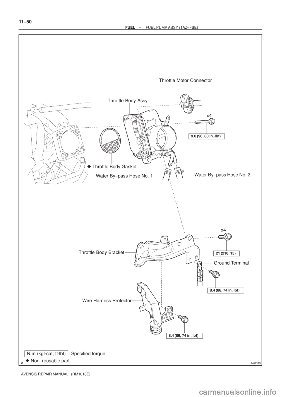
A78508� Non±reusable part
N´m (kgf´cm, ft´lbf) : Specified torqueThrottle Body AssyThrottle Motor Connector
� Throttle Body Gasket
Water By±pass Hose No. 2
Water By±pass Hose No. 1
9.0 (90, 80 in.�lbf)
x4
x4
21 (210, 15)Throttle Body Bracket
8.4 (86, 74 in.�lbf)
Ground Terminal
Wire Harness Protector
8.4 (86, 74 in.�lbf)
11±50
± FUELFUEL PUMP ASSY (1AZ±FSE)
AVENSIS REPAIR MANUAL (RM1018E)
Page 1878 of 5135
A78508� Non±reusable part
N´m (kgf´cm, ft´lbf) : Specified torqueThrottle Body AssyThrottle Motor Connector
� Throttle Body Gasket
Water By±pass Hose No. 2
Water By±pass Hose No. 1
9.0 (90, 80 in.�lbf)
x4
x4
21 (210, 15)Throttle Body Bracket
8.4 (86, 74 in.�lbf)
Ground Terminal
Wire Harness Protector
8.4 (86, 74 in.�lbf)
11±38
± FUELFUEL INJECTOR ASSY (1AZ±FSE)
AVENSIS REPAIR MANUAL (RM1018E)
Page 1986 of 5135

14±1
AVENSIS REPAIR MANUAL (RM1018E)
ENGINE(1ZZ±FE/3ZZ±FE)
INSPECTION
1.INSPECT COOLANT (See page 16±1)
2.INSPECT ENGINE")
140KR±02
A62199
TCCG
A62200
±
ENGINE MECHANICAL ENGINE(1ZZ±FE/3ZZ±FE)
14±1
AVENSIS REPAIR MANUAL (RM1018E)
ENGINE(1ZZ±FE/3ZZ±FE)
INSPECTION
1.INSPECT COOLANT (See page 16±1)
2.INSPECT ENGINE OIL (See page 17±1)
3.INSPECT BATTERY (See page 19±5)
4.INSPECT AIR CLEANER FILTER ELEMENT SUB±ASSY
5.INSPECT SPARK PLUG (See page 18±3)
6.INSPECT FAN AND GENERATOR V BELT
HINT:
You don't need to check the belt deflection because auto tensioner is ado\
pted.
7.INSPECT IGNITION TIMING
(a)Warm up engine.
(b)When using hand±held tester:
(1)Connect the hand±held tester to the DLC3.
(2)Enter DATA LIST MODE on the hand±held tester.
Ignition timing: 8 to 12 �BTDC
HINT:
Please refer to the hand±held tester operator's manual if you
need help to select DATA LIST.
(c) When not using hand±held tester: (1) Using SST, connect terminal 13 (TC) and 4 (CG) ofthe DLC3.
SST 09843±18040
NOTICE:
�Make sure of the terminal numbers before connecting
them. Connection with a wrong terminal can damage
the engine.
�Turn OFF all electrical systems before connecting the
terminals.
�Operate the inspection after the cooling fan motor is
turned OFF
(2) Remove the 2 nuts, and 2 clips, and then remove the cylinder head cover.
(3) Pull out the wire harness as shown in the illustration.
(4) Connect the clip of the timing light to the engine.
NOTICE:
�Use a timing light which detects the first signal.
�After checking, be sure to wrap the wire harness with
tape.
Page 2099 of 5135

14±101
AVENSIS REPAIR MANUAL (RM1018E)
ENGINE(1AZ±FE)
INSPECTION
1.INSPECT COOLANT (See page 16±13)
2.INSPECT ENGINE OIL (See pag")
140D1±02
CG
TCA51075
A52004
±
ENGINE MECHANICAL ENGINE(1AZ±FE)
14±101
AVENSIS REPAIR MANUAL (RM1018E)
ENGINE(1AZ±FE)
INSPECTION
1.INSPECT COOLANT (See page 16±13)
2.INSPECT ENGINE OIL (See page 17±6)
3. INSPECT BATTERY
Standard specific gravity: 1.25 to 1.29 at 20 �C (68 �F)
4. INSPECT AIR CLEANER FILTER ELEMENT SUB±ASSY
5.INSPECT SPARK PLUG (See page 18±9)
6. INSPECT V±RIBBED BELT
7. INSPECT IGNITION TIMING
(a) Warm up engine.
(b) When using hand±held tester:(1) Connect the hand±held tester to the DLC3.
(2) Enter DATA LIST MODE on the hand±held tester.
Ignition timing: 8 to 12 � BTDC
HINT:
Please refer to the hand±held tester operator's manual if you
need help to select DATA LIST.
(c) When not using hand±held tester:
(1) Using SST, connect terminals 13 (TC) and 4 (CG)of DLC3.
SST 09843±18040
NOTICE:
�Make sure of the terminal numbers before connecting
them. Connection with a wrong terminal can damage
the engine.
�Turn OFF all electrical systems before connecting the
terminals.
�Operate the inspection after the cooling fan motor is
turned OFF.
(2) Remove the cylinder head cover No.2.
(3) Pull out the wire harness as shown in the illustration.
Connect the clip of the timing light to the engine.
NOTICE:
�Use a timing light which detects the first signal.
�After checking, be sure to wrap the wire harness with
tape.
(4) Inspect ignition timing at idle.
Ignition timing: 8 to 12 � BTDC
NOTICE:
When checking the ignition timing, shift the transmission
to the neutral position.
HINT:
Run the engine at 1,000 to 1,300 rpm for 5 seconds, check that
the engine rpm returns to the idle speed.
Page 2128 of 5135

14±181
AVENSIS REPAIR MANUAL (RM1018E)
ENGINE(1AZ±FSE)
INSPECTION
1.INSPECT COOLANT (See page 16±25)
2.INSPECT ENGINE OIL(See pa")
141CP±01
CG
TCA51075
A79034
±
ENGINE MECHANICAL ENGINE(1AZ±FSE)
14±181
AVENSIS REPAIR MANUAL (RM1018E)
ENGINE(1AZ±FSE)
INSPECTION
1.INSPECT COOLANT (See page 16±25)
2.INSPECT ENGINE OIL(See page 17±13)
3.INSPECT BATTERY
Standard specific gravity: 1.25 to 1.29 at 20 �C (68 �F)
4.INSPECT AIR CLEANER FILTER ELEMENT SUB±ASSY
5.INSPECT SPARK PLUG (See page 18±14)
6.INSPECT V±RIBBED BELT
7.INSPECT IGNITION TIMING
(a)Warm up engine.
(b)When using hand±held tester:(1)Connect the hand±held tester to the DLC3.
(2)Enter DATA LIST MODE on the hand±held tester.
Ignition timing: 8 to 12 � BTDC
HINT:
Please refer to the hand±held tester operator's manual if you
need help to select DATA LIST.
(c) When not using hand±held tester:
(1) Using SST, connect terminals 13 (TC) and 4 (CG)of DLC3.
SST 09843±18040, 09843±18020
NOTICE:
�Make sure of the terminal numbers before connecting
them. Connection with a wrong terminal can damage
the engine.
�Turn OFF all electrical systems before connecting the
terminals.
�Operate the inspection after the cooling fan motor is
turned OFF
(2) Remove the cylinder head cover No.2.
(3) Pull out the wire harness as shown in the illustration.
Connect the clip of the timing light to the engine.
NOTICE:
�Use a timing light which detects the first signal.
�After checking, be sure to wrap the wire harness with
tape.
(4) Inspect ignition timing at idle.
Ignition timing: 8 to 12 � BTDC
NOTICE:
When checking the ignition timing, shift the transmission
to the neutral position.
HINT:
Run the engine at 1,000 to 1,300 rpm for 5 seconds, check that
the engine rpm returns to the idle speed. (5) Disconnect terminals 13 (TC) and 4 (CG) of DLC3.
Page 2381 of 5135
160MS±01
16±36
±
COOLING RADIATOR ASSY(1AZ±FSE)
AVENSIS REPAIR MANUAL (RM1018E)
RADIATOR ASSY(1AZ±FSE)
REPLACEMENT
1.DRAIN COOLANT (See page 16±31)
2.REMOVE RADIATOR SUPPORT OPENING COVER
3.REMOVE ENGINE ROOM COVER SIDE
4.REMOVE ENGINE UNDER COVER RH
5.DISCONNECT RADIATOR HOSE INLET
6.DISCONNECT RADIATOR HOSE OUTLET
7.REMOVE RADIATOR SUPPORT UPPER
(a)Disconnect the fan w/ motor wire harness, connector and the horn connect\
or.
(b)Remove 4 bolts, the nut and the radiator support.
8.REMOVE RADIATOR ASSY
(a)Remove 2 upper support, and radiator assembly
9.REMOVE RADIATOR SUPPORT LOWER
10.REMOVE FAN ASSY W/MOTOR
(a)Remove 6 bolts and fan w/motor.
11.INSTALL FAN ASSY W/MOTOR
12.INSTALL RADIATOR SUPPORT LOWER
13.INSTALL RADIATOR ASSY
14.INSTALL RADIATOR SUPPORT UPPER
(a)Install radiator support with 2 bolts. Torque: 19 N �m (194 kgf �cm,14 ft �lbf)
15.ADD COOLANT (See page 16±31)
16.INSPECT CHECK FOR ENGINE COOLANT LEAKS (See page 16±25)
Page 2393 of 5135
160MX±01
16±24
±
COOLING RADIATOR ASSY(1AZ±FE)
AVENSIS REPAIR MANUAL (RM1018E)
RADIATOR ASSY(1AZ±FE)
REPLACEMENT
1.DRAIN COOLANT (See page 16±19)
2.REMOVE RADIATOR SUPPORT OPENING COVER
3.REMOVE ENGINE ROOM COVER SIDE
4.REMOVE ENGINE UNDER COVER RH
5.DISCONNECT RADIATOR HOSE INLET
6.DISCONNECT RADIATOR HOSE OUTLET
7.REMOVE RADIATOR SUPPORT UPPER
(a)Disconnect the fan w/ motor wire harness, connector and the horn connect\
or.
(b)Remove 4 bolts, the nut and the radiator support.
8.REMOVE RADIATOR ASSY
(a)Remove 2 upper support, and radiator assembly
9.REMOVE RADIATOR SUPPORT LOWER
10.REMOVE FAN ASSY W/MOTOR
(a)Remove 6 bolts and fan w/motor.
11.INSTALL FAN ASSY W/MOTOR
12.INSTALL RADIATOR SUPPORT LOWER
13.INSTALL RADIATOR ASSY
14.INSTALL RADIATOR SUPPORT UPPER
(a)Install radiator support with 2 bolts. Torque: 19 N �m (194 kgf �cm,14 ft �lbf)
15.ADD COOLANT (See page 16±19)
16.INSPECT CHECK FOR ENGINE COOLANT LEAKS (See page 16±13)


AVENSIS REPAIR MANUAL (RM1018E)
RADIATOR ASSY(1AZ±FSE)
REPLACEMENT
1.DRAIN COOLANT (See page 16±31)
2.REMOVE RADIATOR SUPPORT OPENING COVER
3.RE")

AVENSIS REPAIR MANUAL (RM1018E)
RADIATOR ASSY(1AZ±FE)
REPLACEMENT
1.DRAIN COOLANT (See page 16±19)
2.REMOVE RADIATOR SUPPORT OPENING COVER
3.REMO")