Page 2802 of 5135
F44857F44857
LHD:RHD:
Torque Sensor Wire Harness Clamp
Marks
Power Steering ECU Assy
Front
Motor Wire Harness
Torque Sensor
Wire Harness
Front
Torque Sensor
Wire Harness
Motor Wire Harness
Power Steering ECU Assy
Torque Sensor Wire Harness Clamp
Marks
Bolt (A)
Bolt (B)
ScrewScrew Bolt (B)Bolt (A)
± STEERING COLUMNPOWER STEERING ECU ASSY
50±21
AVENSIS REPAIR MANUAL (RM1018E)
17. INSTALL POWER STEERING ECU ASSY
(a) LHD:
Install the power steering ECU assy with the 2 bolts and
screw.
Torque:
BOLT (A): 8.0 N�m (82 kgf�cm, 71 in.�lbf)
BOLT (B): 15.5 N�m (158 kgf�cm, 11 ft�lbf)
(b) RHD:
Install the power steering ECU assy with the 2 bolts and
2 screws.
Torque:
BOLT (A): 8.0 N�m (82 kgf�cm, 71 in.�lbf)
BOLT (B): 15.5 N�m (158 kgf�cm, 11 ft�lbf)
(c) Connect the 4 connectors.
(d) Align the marks on the torque sensor wire harness with
the clamp, as shown in the illustration.
Page 2807 of 5135
F44857F44857
LHD:RHD:
Torque Sensor Wire Harness Clamp
Marks
Power Steering ECU Assy
Front
Motor Wire Harness
Torque Sensor
Wire Harness
Front
Torque Sensor
Wire Harness
Motor Wire Harness
Power Steering ECU Assy
Torque Sensor Wire Harness Clamp
Marks 50±12
± STEERING COLUMNSTEERING COLUMN ASSY
AVENSIS REPAIR MANUAL (RM1018E)
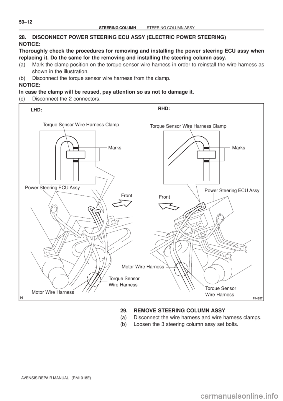
28. DISCONNECT POWER STEERING ECU ASSY (ELECTRIC POWER STEERING)
NOTICE:
Thoroughly check the procedures for removing and installing the power steering ECU assy when
replacing it. Do the same for the removing and installing the steering column assy.
(a) Mark the clamp position on the torque sensor wire harness in order to reinstall the wire harness as
shown in the illustration.
(b) Disconnect the torque sensor wire harness from the clamp.
NOTICE:
In case the clamp will be reused, pay attention so as not to damage it.
(c) Disconnect the 2 connectors.
29. REMOVE STEERING COLUMN ASSY
(a) Disconnect the wire harness and wire harness clamps.
(b) Loosen the 3 steering column assy set bolts.
Page 2809 of 5135
F44793Matchmarks
F44794
Screw
Extractor
F44795
SST
F44796
F44797
50±14
±
STEERING COLUMN STEERING COLUMN ASSY
AVENSIS REPAIR MANUAL (RM1018E)
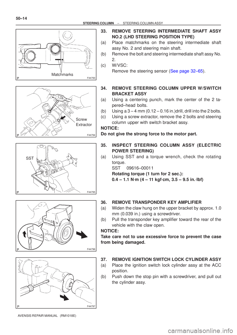
33. REMOVE STEERING INTERMEDIATE SHAFT ASSY NO.2 (LHD STEERING POSITION TYPE)
(a) Place matchmarks on the steering intermediate shaft
assy No. 2 and steering main shaft.
(b) Remove the bolt and steering intermediate shaft assy No. 2.
(c) W/VSC:
Remove the steering sensor (See page 32±65).
34. REMOVE STEERING COLUMN UPPER W/SWITCH BRACKET ASSY
(a) Using a centering punch, mark the center of the 2 ta- pered±head bolts.
(b) Using a 3 ± 4 mm (0.12 ± 0.16 in.)drill, drill into the 2 bolts.
(c) Using a screw extractor, remove the 2 bolts and steering column upper with switch bracket assy.
NOTICE:
Do not give the strong force to the motor part.
35. INSPECT STEERING COLUMN ASSY (ELECTRIC POWER STEERING)
(a) Using SST and a torque wrench, check the rotating torque.
SST 09616±00011
Rotating torque (1 turn for 2 sec.):
0.4 ± 1.1 N �m (4 ± 11 kgf �cm, 3.5 ± 9.5 in. �lbf)
36. REMOVE TRANSPONDER KEY AMPLIFIER
(a) Widen the claw hung on the upper bracket by approx. 1.0 mm (0.039 in.) using a screwdriver.
(b) Pull the transponder key amplifier toward the rear of the
vehicle with the claw open.
NOTICE:
Take care not to use excessive force to prevent the case
from being damaged.
37. REMOVE IGNITION SWITCH LOCK CYLINDER ASSY
(a) Place the ignition switch lock cylinder assy at the ACC position.
(b) Push down the stop pin with a screwdriver, and pull out the cylinder assy.
Page 2813 of 5135
F44857F44857
LHD:RHD:
Torque Sensor Wire Harness Clamp
Marks
Power Steering ECU Assy
Front
Motor Wire Harness
Torque Sensor
Wire Harness
Front
Torque Sensor
Wire Harness
Motor Wire Harness
Power Steering ECU Assy
Torque Sensor Wire Harness Clamp
Marks
F44786
50±18
± STEERING COLUMNSTEERING COLUMN ASSY
AVENSIS REPAIR MANUAL (RM1018E)
52. CONNECT POWER STEERING ECU ASSY (ELECTRIC POWER STEERING)
(a) Connect the 2 connectors.
(b) Align the marks on the torque sensor wire harness with the clamp, as shown in the illustration.
NOTICE:
�When reusing the clamp, check that there is no damage on it.
�When reinstalling the wire harness, make sure there is no twist in the harness or with other wire
harness.
53. INSTALL STEERING COLUMN PROTECTOR NO.1
(a) Install the steering column protector with the 2 bolts.
Torque: 5 N�m (51 kgf�cm, 44 ft�lbf)
(b) Connect the wire harness clamp to the steering colum
protector No.1.
Page 2822 of 5135
5000C±14
±
STEERING COLUMN STEERING SYSTEM
50±1
AVENSIS REPAIR MANUAL (RM1018E)
STEERING SYSTEM
PRECAUTION
1. HANDLING PRECAUTIONS ON STEERING SYSTEM
(a) Be careful to replace the parts properly because they could affect the performance of the steering sys-
tem and result in a driving hazard.
2. HANDLING PRECAUTIONS ON SRS AIRBAG SYSTEM
(a) The vehicle is equipped with SRS (Supplemental Restraint System) such as \
the driver airbag and front passenger airbag. Failure to carry out service operation in the correct sequence \
could cause the SRS
to unexpectedly deploy during servicing, possibly leading to a serious acc\
ident. Before servicing (in-
cluding removal or installation of parts, inspection or replacement), be sure \
to read the precautionary
notices in the supplemental restraint system (See page 60±1).
3. HANDLING PRECAUTIONS ON STEERING COLUMN
(a) Do not give an impact to the steering column assy, especially the motor and the torque sensor. If a great impact is given (dropping it to the floor, etc.), replace it with a new one.
(b) When removing the steering column assy, do not pull the harness.
(c) When having replaced the steering column assy and/or the ECU, calibrate the \
zero point of the steer- ing torque sensor.
(d) In the case of disconnecting a connector related to the power steering sys\
tem, turn the ignition switch ON, set the steering wheel in the straight±ahead position and turn th\
e ignition switch OFF before dis-
connecting the connector.
(e) In the case of connecting a connector related to the power steering system, make sure that the ignit\
ion switch is OFF at first. After connecting the connector, set the steering wheel assy in the straight±ahead
position, and then turn the ignition switch ON.
NOTICE:
Never turn on the ignition switch when the steering wheel assy is set in orde\
r than the straight±ahead
position.
(f) If the above operation is not done, the zero point of the steering torque \
sensor is shifted away from the proper position, making difference in the steering effort between right and left. If this happens, per-
form the zero point calibration of the steering torque sensor (See page 05±1042).
Page 2905 of 5135
I22120
Condition: Air conditioning system does not function. (Sometimes it may function)
I22121
Condition : Air conditioning system does not function effectively. 55±28
± HEATER & AIR CONDITIONERREFRIGERANT
AVENSIS REPAIR MANUAL (RM1018E)
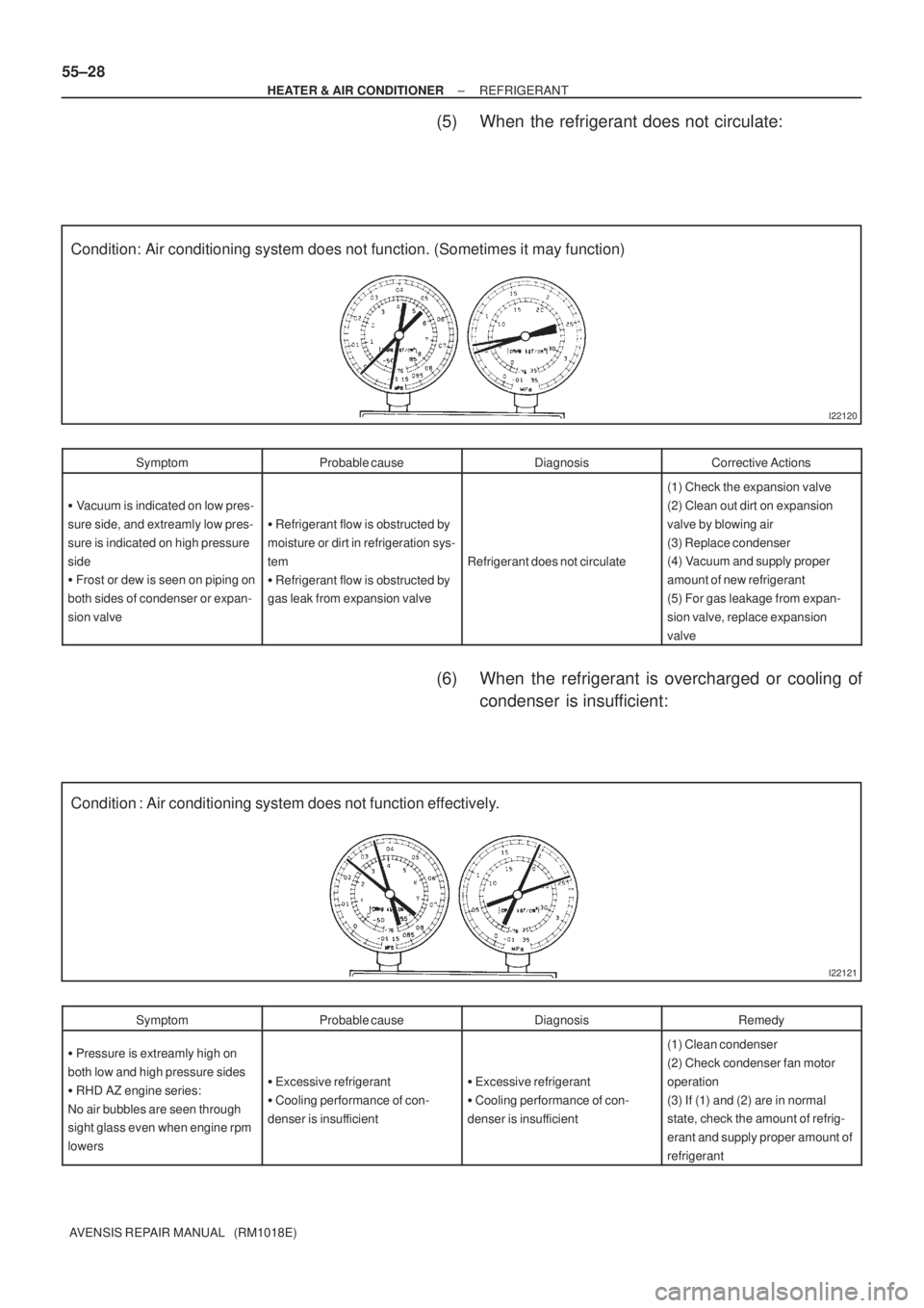
(5) When the refrigerant does not circulate:
SymptomProbable causeDiagnosisCorrective Actions
� Vacuum is indicated on low pres-
sure side, and extreamly low pres-
sure is indicated on high pressure
side
� Frost or dew is seen on piping on
both sides of condenser or expan-
sion valve
� Refrigerant flow is obstructed by
moisture or dirt in refrigeration sys-
tem
� Refrigerant flow is obstructed by
gas leak from expansion valve
Refrigerant does not circulate
(1) Check the expansion valve
(2) Clean out dirt on expansion
valve by blowing air
(3) Replace condenser
(4) Vacuum and supply proper
amount of new refrigerant
(5) For gas leakage from expan-
sion valve, replace expansion
valve
(6) When the refrigerant is overcharged or cooling of
condenser is insufficient:
SymptomProbable causeDiagnosisRemedy
� Pressure is extreamly high on
both low and high pressure sides
� RHD AZ engine series:
No air bubbles are seen through
sight glass even when engine rpm
lowers
� Excessive refrigerant
� Cooling performance of con-
denser is insufficient� Excessive refrigerant
� Cooling performance of con-
denser is insufficient
(1) Clean condenser
(2) Check condenser fan motor
operation
(3) If (1) and (2) are in normal
state, check the amount of refrig-
erant and supply proper amount of
refrigerant
Page 2912 of 5135
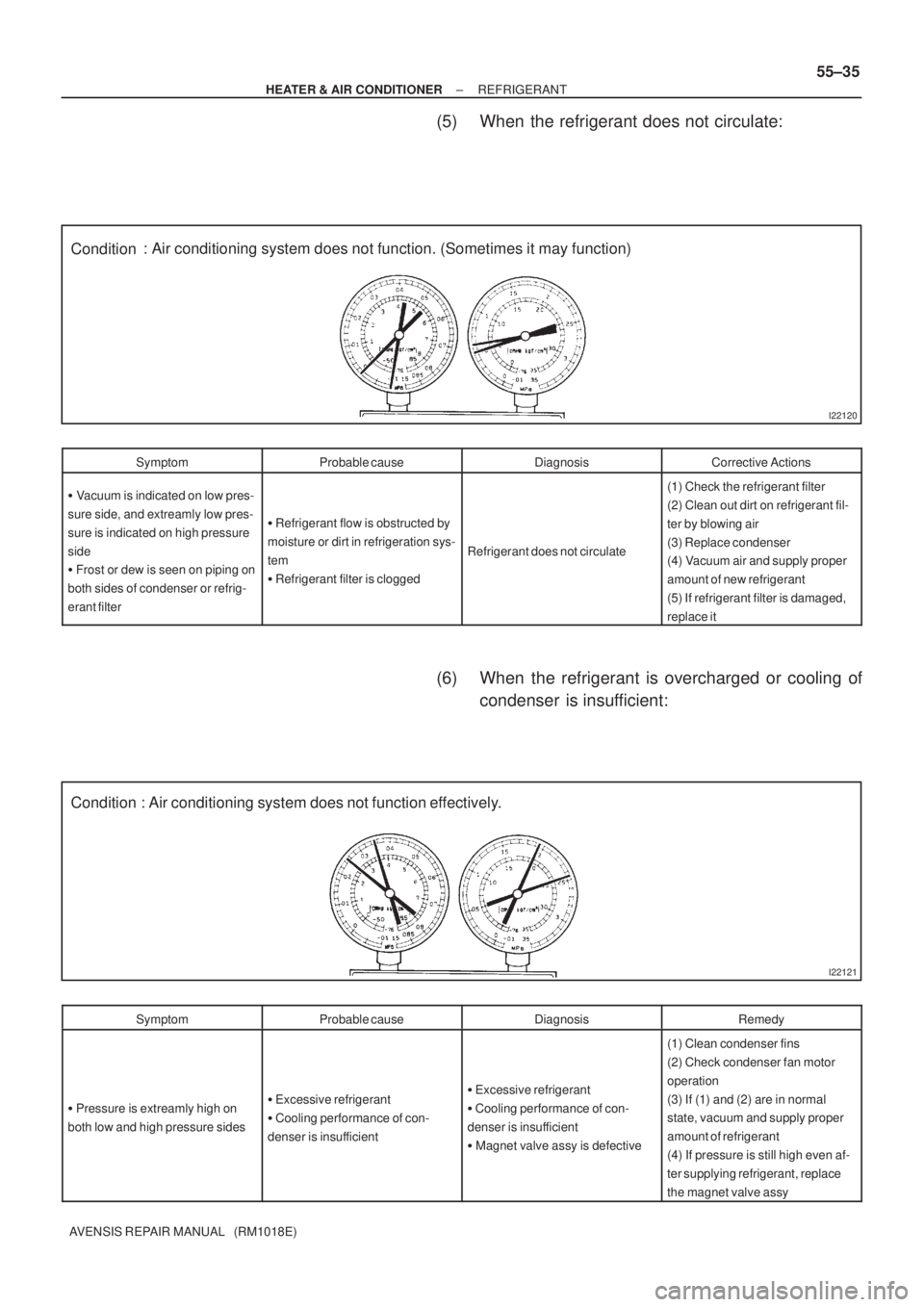
I22120
Condition: Air conditioning system does not function. (Sometimes it may function)
I22121
Condition : Air conditioning system does not function effectively.
± HEATER & AIR CONDITIONERREFRIGERANT
55±35
AVENSIS REPAIR MANUAL (RM1018E)
(5) When the refrigerant does not circulate:
SymptomProbable causeDiagnosisCorrective Actions
� Vacuum is indicated on low pres-
sure side, and extreamly low pres-
sure is indicated on high pressure
side
� Frost or dew is seen on piping on
both sides of condenser or refrig-
erant filter
� Refrigerant flow is obstructed by
moisture or dirt in refrigeration sys-
tem
� Refrigerant filter is clogged
Refrigerant does not circulate
(1) Check the refrigerant filter
(2) Clean out dirt on refrigerant fil-
ter by blowing air
(3) Replace condenser
(4) Vacuum air and supply proper
amount of new refrigerant
(5) If refrigerant filter is damaged,
replace it
(6) When the refrigerant is overcharged or cooling of
condenser is insufficient:
SymptomProbable causeDiagnosisRemedy
� Pressure is extreamly high on
both low and high pressure sides� Excessive refrigerant
� Cooling performance of con-
denser is insufficient� Excessive refrigerant
� Cooling performance of con-
denser is insufficient
� Magnet valve assy is defective
(1) Clean condenser fins
(2) Check condenser fan motor
operation
(3) If (1) and (2) are in normal
state, vacuum and supply proper
amount of refrigerant
(4) If pressure is still high even af-
ter supplying refrigerant, replace
the magnet valve assy
Page 2921 of 5135
I35431
Burner Motor
Glow Plug
Surface Sensor
Temp. Control Sensor
Flame Sensor13
Power
Heater
ECU
Connector BTerminal L
of AlternatorBattery
Metering Pump
Fuse (20 A)
Vehicle Side SW 14
9
12
5
6
3
4
1
2R
BR
B±R
G
L±Y
L
Y
L±W5
1
6
2
7
3
8
4W±B
R±G
R±B Connector A
IG
W±R (*1)
Y±R (*2)
R±L (*1)
R±Y (*2)
*1: TMC Made
*2: TMUK Made 55±16
± HEATER & AIR CONDITIONERCOMBUSTION TYPE POWER HEATER SYSTEM
AVENSIS REPAIR MANUAL (RM1018E)
2. DESCRIPTION OF DISPLAY AND BUTTONS
(a) AF: Current Value Malfunction (Blinking at current failure)
Diag: DTC (Example: 064 Flame sensor break)
Memory Clear button: Deletion of faulty memory (Press both buttons together for longer than 2 se-
conds)
> Button: Scroll up of faulty memory (The past 5 codes can be stored.)
< Button: Scroll down of faulty memory (The past 5 codes can be stored.)
3. FAULTY MEMORY
(a) The ECU is able to store up to 5 pieces of faulty memory. If it is full, the new data is written over F5.
4. WIRING DIAGRAM