Page 2922 of 5135

5. DIAGNOSTIC TROUBLE CODE CHART
If a malfunction code is displayed during the DTC check, check")
± HEATER & AIR CONDITIONERCOMBUSTION TYPE POWER HEATER SYSTEM
55±17
AVENSIS REPAIR MANUAL (RM1018E)
5. DIAGNOSTIC TROUBLE CODE CHART
If a malfunction code is displayed during the DTC check, check the circuit listed for the code in the table below
and proceed to the appropriate page.
DTC No.Description of faultComment / Remedy
000No malfunction±
010
011Overvoltage shutoff
Undervoltage shutoffVoltage between 1 and 5 at connector A > 16 V
Voltage between 1 and 5 at connector A < 10.2 V
(Voltage values must be present > 20 seconds)
Check battery, regulator and electrical leads.
012Overheating
Check temperature at temperature or overheating sensor >
125 �C
Check water circuit.
014Possible overheating detected
(Hardware threshold value)
Difference of measured values at temperature sensor > 15 �C
(min. 70 �C water temperature and metering pump in opera-
tion);
Check temperature sensor and overheating sensor, replace if
necessary.
017Overheating detected
(Hardware threshold value)
Temperature at temperature or overheating sensor > 130 �C,
emergency OFF if DTC No. 012 or 014s not applicable;
Check water circuit, temperature sensor and overheating sen-
sor, replace if necessary.
020Glow plug breakCheck glow plug, replace if necessary.
021Glow plug output overloadCheck glow plug, replace if necessary.
030Combustion air blower motor
EMF outside perm. range.Blower impeller or burner motor fammed (frozen solid, dirty,
etc.)
Remedy jam, replace burner motor if necessary.
031Combustion air blower motor breakCheck the lead to combustion air motor (burner motor) for
continuity, replace if necessary.
032Combustion air blower motor short±circuit
Check combustion air blower motor (burner motor), replace if
necessary.
Check supply lead (chafed, etc.).
047Metering pump short±circuitCheck the supply lead to metering pump for short±circuit,
check metering pump, replace if necessary.
048Metering pump breakCheck the supply lead to metering pump for continuity, remedy
break, replace metering pump if necessary.
051Cold blow time exceeded
At start, if flame sensor above 70 �C, > 240 sec.;
Check exhaust gas combustion air supply, check flame sen-
sor, replace if necessary.
052Safety time exceeded
When all perm. start attempts used up;
Check the fuel delivery and fuel supply.
Check exhaust gas and combustion air ducts.
054Flame cutout, High settingCheck the fuel delivery and fuel supply.
Check exhaust gas combustion air ducts.
056Flame cutout, LOW setting
Check exhaust gas combustion air ducts.
If combustion OK � Check the flame sensor, replace if neces-
sary.
060Temperature control sensor break
Check connecting leads.
Resistance value between 2 and 10 connector B > 2 M� (if
break)
061Temperature control sensor short±circuit
Check connecting leads.
Resistance value between 2 and 10 at connector B < 2 M� (If
short± circuit)
064Flame sensor break
Check connecting leads.
Resistance value between 7 and 14 at connector B > 3,040 �
(If break)
065Flame sensor short±circuit
Check connecting leads.
Resistance value between 7 and 14 at connector B > 780 � (If
short±circuit)
Page 2927 of 5135
I36092
LHD Models:REC
FRS
I36094
I36093
RHD Models:
RECFRS
I36094
55±8
± HEATER & AIR CONDITIONERAIR CONDITIONING SYSTEM
AVENSIS REPAIR MANUAL (RM1018E)
3. INSPECT RECIRCULATION DAMPER SERVO
SUB±ASSY (MANUAL AIR CONDITIONING)
(a) Inspect servomotor operation.
(1) Connect the positive (+) lead from the battery to ter-
minal 3 and negative (±) lead to terminal 2, then
check that the arm turns to ºFRSº side smoothly.
(2) Connect the positive (+) lead from the battery to ter-
minal 3 and negative (±) lead to terminal 1, then
check that the arm turns to ºRECº side smoothly.
If operations are not as specified, replace the mode damper
servomotor.
Page 2928 of 5135
I30157
I30162
To ºMAX HOTº
To ºMAX COOLº
± HEATER & AIR CONDITIONERAIR CONDITIONING SYSTEM
55±9
AVENSIS REPAIR MANUAL (RM1018E)
4. INSPECT AIRMIX DAMPER SERVO SUB±ASSY
(MANUAL AIR CONDITIONING)
(a) Inspect servomotor operation.
(1) Connect the positive (+) lead from the battery to ter-
minal 4 and negative (±) lead to terminal 5, then
check that the arm turns to ºMAX COOLº side
smoothly.
(2) Connect the positive (+) lead from the battery to ter-
minal 5 and negative (±) lead to terminal 4, then
check that the arm turns to ºMAX HOTº side
smoothly.
If operations are not as specified, replace the servomotor.
Page 2929 of 5135
I30157
I30116
To ºDEFº
To ºFACEº 55±10
± HEATER & AIR CONDITIONERAIR CONDITIONING SYSTEM
AVENSIS REPAIR MANUAL (RM1018E)
5. INSPECT MODE DAMPER SERVO SUB±ASSY
(MANUAL AIR CONDITIONING)
(a) Inspect servomotor operation.
(1) Connect the positive (+) lead from the battery to ter-
minal 4 and negative (±) lead to terminal 5, then
check that the arm turns to ºDEFº side smoothly.
(2) Connect the positive (+) lead from the battery to ter-
minal 5 and negative (±) lead to terminal 4, then
check that the arm turns to ºFACEº side smoothly.
If operations are not as specified, replace the servomotor.
Page 2930 of 5135
�
�
E50650
I30145
40
30
20
10
8
6
4
2
0
±30 ±20 ±10 0 10 20 30 50 60 70 8040 Resistance (k�)
Temperature (�C)
I30151
2
1
LHD
RHD
± HEATER & AIR CONDITIONERAIR CONDITIONING SYSTEM
55±11
AVENSIS REPAIR MANUAL (RM1018E)
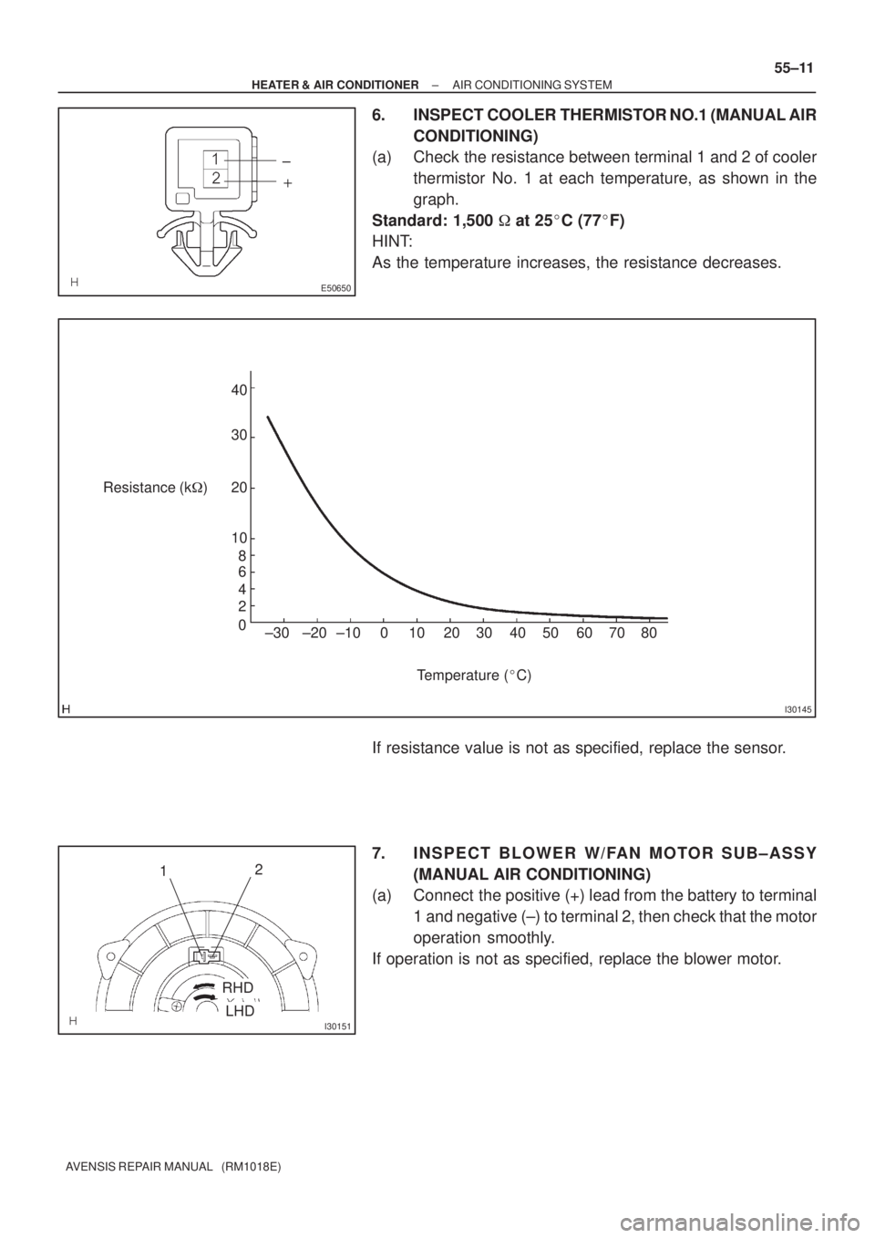
6. INSPECT COOLER THERMISTOR NO.1 (MANUAL AIR
CONDITIONING)
(a) Check the resistance between terminal 1 and 2 of cooler
thermistor No. 1 at each temperature, as shown in the
graph.
Standard: 1,500 � at 25�C (77�F)
HINT:
As the temperature increases, the resistance decreases.
If resistance value is not as specified, replace the sensor.
7. INSPECT BLOWER W/FAN MOTOR SUB±ASSY
(MANUAL AIR CONDITIONING)
(a) Connect the positive (+) lead from the battery to terminal
1 and negative (±) to terminal 2, then check that the motor
operation smoothly.
If operation is not as specified, replace the blower motor.
Page 2932 of 5135

PROBLEM SYMPTOMS TABLE
Use the table below to help you find the cause of the problem. The numbers")
550RQ±02
55±6
±
HEATER & AIR CONDITIONER AIR CONDITIONING SYSTEM
AVENSIS REPAIR MANUAL (RM1018E)
PROBLEM SYMPTOMS TABLE
Use the table below to help you find the cause of the problem. The numbers \
indicate the priority of the likely
cause of the problem. Check each part in order. If necessary, replace these parts.
SymptomSuspect AreaSee page
Whole functions of the A/C system does not operate.
4. ECU±B fuse
5. A/C amplifier assy
6. Wire harness or connector±
55±3 ±
Air Flow Control : No blower operation
1. Blower resistor
2. Heater relay
3. Blower w/ fan motor sub±assy
4. A/C amplifier assy
5. Wire harness or connector55±7
55±7
55±7
55±3±
Air Flow Control : No blower control
1. Blower w/fan motor sub±assy
2. Blower resistor
3. A/C amplifier assy
4. Wire harness or connector55±7
55±7
55±3
±
Air Flow Control : Insufficient air out
1. Blower w/fan motor sub±assy
2. Blower resistor
3. A/C amplifier assy
4. Wire harness or connector55±7
55±7
55±3±
Temperature Control : No cool air comes out
1. Volume of refrigerant
2. Drive belt tension
3. Refrigerant pressure
4. Cooler compressor assy
5. Pressure sensor
6. Condenser fan
7. Air mix damper servo sub±assy
8. A/C amplifier assy
9. Wire harness or connector55±24
55±46
55±2455±7
55±3 ±
55±7
55±3 ±
Temperature Control : No warm air comes out
1. Engine coolant volume
2. Cooler thermistor No.1
3. Air mix damper servo sub±assy
4. A/C amplifier assy
5. Heater radiator unit sub±assy
6. Wire harness or connector55±7
55±3
55±7
55±3±
±
Temperature Control : Output air is warmer or cooler than the set
temperature or response is slow.1. A/C amplifier assy
2. Air mix damper servo sub±assy
3. Air mix level55±3
55±7
±
Temperature Control : No temperature control
1. A/C amplifier assy
2. Air mix damper servo sub±assy
3. Air mix level55±3
55±7±
No air inlet control
1. Recirculation damper servo sub±assy
2. A/C amplifier assy
3. Wire harness or connector55±7
55±3±
No air outlet control
1. A/C amplifier assy
2. Mode damper servo sub±assy
3. Mode lever55±3
55±7±
Engine idle up does not occur, or is continuous
1. Idle up switch
2. Cooler compressor assy
3. A/C amplifier assy
4. Wire harness or connector55±7
55±7
55±3±
Brightness does not changes when rheostat volume or light con-
trol switch it turned.1. Illumination light system
2. A/C amplifier assy
3. Wire harness or connector±
55±3 ±
Page 2956 of 5135
I35321
I35322
I35317
I36813
I35314
± HEATER & AIR CONDITIONERBLOWER ASSY
55±67
AVENSIS REPAIR MANUAL (RM1018E)
11. REMOVE BLOWER MOTOR CONTROL (AUTO AIR
CONDITIONING)
(a) Remove the 2 screws and the blower motor control.
12. REMOVE BLOWER W/FAN MOTOR SUB±ASSY
(a) Remove the 3 screws and the blower w/ fun motor sub±
assy.
13. INSTALL AIR FILTER
(a) Install the air filter as shown in the illustration.
14. INSTALL BLOWER ASSY
(a) Install the blower assy with the claw fitting.
(b) Install the blower assy with the 2 bolts and the 2 screws.
Torque: 9.8 N�m (100 kgf�cm, 87 in.�lbf) (Bolt)
(c) Install the 2 nuts.
(d) Connect the connectors.
Page 2958 of 5135
550YQ±01
I35277
Blower Assy
Air Duct No.2
Recirculation Damper Servo Sub±assy
Air Filter
Air Filter Case
Blower w/ fan Motor Sub±assy
Manual A/C:
Blower Resistor Air Conditioning Wire No.1
Auto A/C:
Blower Motor Control
9.8 (100, 87 in.�lbf)
Cooler Wiring No.1Manual A/C:
N�m (kgf�cm, ft�lbf): Specified torque
55±64
± HEATER & AIR CONDITIONERBLOWER ASSY
AVENSIS REPAIR MANUAL (RM1018E)
BLOWER ASSY
COMPONENTS

3. INSPECT RECIRCULATION DAMPER SERVO
SUB±")

4. INSPECT AIRMIX DAMPER SERVO SUB±ASSY
(MANUAL AIR CONDITIONIN")

5. INSPECT MODE DAMPER SERVO SUB±ASSY
(MANUAL AIR CONDITIONING)
(a) In")

11. REMOVE BLOWER MOTOR CONTROL (AUTO AIR
CONDITIONING)
(a) Remove the 2 screws and t")
