A64023
A93668
A64026
A96570
14–16– ENGINE MECHANICALPARTIAL ENGINE ASSY (1ZZ–FE/3ZZ–FE)(From
February, 2004)
AVENSIS REPAIR MANUAL SUPPLEMENT
(RM1098E)
(c) Remove the 4 bolts and 4 ignition coils.
68. REMOVE FUEL DELIVERY PIPE SUB–ASSY
(See Pub. No. RM1018E on page 11–11)
69. REMOVE INTAKE MANIFOLD
(a) Disconnect the throttle motor connector.
(b) Disconnect the 2 water hoses from the throttle body.
(c) Disconnect the ventilation hose and ventilation hose No.
2 from the cylinder head cover.
(d) Disconnect the vacuum hose from water by–pass pipe
No. 1.
(e) Remove the 4 bolts, 2 nuts and 2 wire brackets,then re-
move the intake manifold and throttle body assembly.
(f) Remove the gasket from the intake manifold and the
throttle body assembly.
70. REMOVE OIL LEVEL GAGE SUB–ASSY
(a) Remove the oil level gage from the oil level gage guide.
71. REMOVE OIL LEVEL GAGE GUIDE
(a) Disconnect the crankshaft position sensor clamp.
(b) Remove the bolt and oil level gage guide.
72. REMOVE WATER BY–PASS PIPE NO.1
(a) Disconnect the knock sensor clamp.
(b) Remove the 2 bolts and 2 nuts, then detach the water by–
pass pipe and gasket.
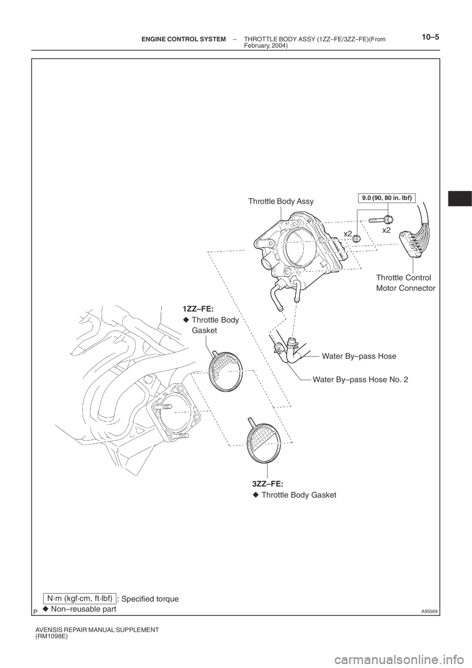
A95569
Throttle Body Assy
Throttle Control
Motor Connector
Water By–pass Hose No. 2Water By–pass Hosex2x2
� Throttle Body
Gasket
N·m (kgf·cm, ft·lbf)
: Specified torque
� Non–reusable part
9.0 (90, 80 in.⋅lbf)
1ZZ–FE:
� Throttle Body Gasket 3ZZ–FE:
– ENGINE CONTROL SYSTEMTHROTTLE BODY ASSY (1ZZ–FE/3ZZ–FE)(From
February, 2004)10–5
AVENSIS REPAIR MANUAL SUPPLEMENT
(RM1098E)
(From
February, 2004)
AVENSIS REPAIR MANUAL SUPPLEMENT
(RM1098E)
(c) Remove the 4 bolts and 4 ignition co")