Page 1606 of 5135
B66822
DLPD
ACTR
ACTS
Front Door w/ Motor Lock Assy RH
Rear Door w/ Motor Lock Assy RH
Front Door w/ Motor Lock Assy LHIntegration Relay
Instrument Panel J/B Assy
I146
D14
D14
D14 D14
9
3
4 10
DJ6
DJ9
D21
D21
D21
5
2 1
D21
D16
D16
D16
6
2 1
D165
Rear Door w/ Motor Lock Assy LH
D19
D19
D19
9
3
4
D1910
RHD Models w/ Double Lock Only
IL2 J20 J21
IC1
IPCJ
CA CH
CF
CE
CI
CK
CB
CA
CD IM1 BC1 IL1
W±B
BC1
BU
IA1B
IA1
17
J20
J20
G
G
GJ/C
J21
G
GB
B3W±B
W±BIL1
IL1
4 8
W
LW
L 5
6
1
1
2
2 3
5 6
10
W±B
W±B
W±B
IJW
L
IA1IA2
W
LW
L
W
L
W
L10 12
BC1
BC1IM2
IM2
4
16
617
11
2
17
4 8
W±B
BA1
10
W±B
BQW
LB
BB
W
L
B
W
L
W
L
IC1
IC3
IC3 BA1
BA1
BA1
4
16
6
4 10 12 9B
B
B BB
9
W
L
W
L15
14 Center J/B
± DIAGNOSTICSPOWER DOOR LOCK CONTROL SYSTEM
05±1561
AVENSIS REPAIR MANUAL (RM1018E)
WIRING DIAGRAM
Page 1608 of 5135
B64708
Lock Unlock
± DIAGNOSTICSPOWER DOOR LOCK CONTROL SYSTEM
05±1563
AVENSIS REPAIR MANUAL (RM1018E)
3 INSPECT FRONT DOOR W/MOTOR LOCK ASSY RH
(a) Front Door w/ Motor Lock Assy RH:
Inspect operation of the double lock motor.
(1) Apply battery voltage and set the door lock motor to
set.
(2) Apply battery voltage to the double lock motor and
inspect operation.
Standard:
Measurement ConditionSpecified Condition
Battery positive (+) � Terminal 4
Battery negative (±) � Terminal 3Double locking system is Set
Battery positive (+) � Terminal 3
Battery negative (±) � Terminal 4Double locking system is Unset
(3) Check that the doors cannot be unlocked by operat-
ing the control cable while the double locking sys-
tem is set.
(4) Inspect the resistance of the double lock position
switch.
Standard:
Tester ConnectionDouble Lock PositionSpecified Condition
910SETBelow 1 �9 ± 10UNSET10 k�or higher
NG REPLACE FRONT DOOR W/MOTOR LOCK
ASSY RH
OK
Page 1609 of 5135
B64707
Unlock
Lock
05±1564
± DIAGNOSTICSPOWER DOOR LOCK CONTROL SYSTEM
AVENSIS REPAIR MANUAL (RM1018E)
4 INSPECT FRONT DOOR W/MOTOR LOCK ASSY LH
(a) Front Door w/ Motor Lock Assy LH:
Inspect operation of the double lock motor.
(1) Apply battery voltage and set the door lock motor to
set.
(2) Apply battery voltage to the double lock motor and
inspect operation.
Standard:
Measurement ConditionSpecified Condition
Battery positive (+) � Terminal 2
Battery negative (±) � Terminal 1Double locking system is Set
Battery positive (+) � Terminal 1
Battery negative (±) � Terminal 2Double locking system is Unset
(3) Check that the doors cannot be unlocked by operat-
ing the control cable while the double locking sys-
tem is set.
(4) Inspect the resistance of the double lock position
switch.
Standard:
Tester ConnectionDouble Lock PositionSpecified Condition
56SETBelow 1 �5 ± 6UNSET10 k�or higher
NG REPLACE FRONT DOOR W/MOTOR LOCK
ASSY LH
OK
Page 1610 of 5135
B64706
Unlock Lock
± DIAGNOSTICSPOWER DOOR LOCK CONTROL SYSTEM
05±1565
AVENSIS REPAIR MANUAL (RM1018E)
5 INSPECT REAR DOOR W/MOTOR LOCK ASSY RH
(a) Rear Door w/ Motor Lock Assy RH:
Inspect operation of the double lock motor.
(1) Apply battery voltage and set the door lock motor to
set.
(2) Apply battery voltage to the double lock motor and
inspect operation.
Standard:
Measurement ConditionSpecified Condition
Battery positive (+) � Terminal 2
Battery negative (±) � Terminal 1Double locking system is Set
Battery positive (+) � Terminal 1
Battery negative (±) � Terminal 2Double locking system is Unset
(3) Check that the doors cannot be unlocked by operat-
ing the control cable while the double locking sys-
tem is set.
(4) Inspect the resistance of the double lock position
switch.
Standard:
Tester ConnectionDouble Lock PositionSpecified Condition
56SETBelow 1 �5 ± 6UNSET10 k�or higher
NG REPLACE REAR DOOR W/MOTOR LOCK ASSY
RH
OK
Page 1611 of 5135
B64705
Unlock Lock
05±1566
± DIAGNOSTICSPOWER DOOR LOCK CONTROL SYSTEM
AVENSIS REPAIR MANUAL (RM1018E)
6 INSPECT REAR DOOR W/MOTOR LOCK ASSY LH
(a) Rear Door w/ Motor Lock Assy LH:
Inspect operation of the double lock motor.
(1) Apply battery voltage and set the door lock motor to
set.
(2) Apply battery voltage to the double lock motor and
inspect operation.
Standard:
Measurement ConditionSpecified Condition
Battery positive (+) � Terminal 4
Battery negative (±) � Terminal 3Double locking system is Set
Battery positive (+) � Terminal 3
Battery negative (±) � Terminal 4Double locking system is Unset
(3) Check that the doors cannot be unlocked by operat-
ing the control cable while the double locking sys-
tem is set.
(4) Inspect the resistance of the double lock position
switch.
Standard:
Tester ConnectionDouble Lock PositionSpecified Condition
910SETBelow 1 �9 ± 10UNSET10 k�or higher
NG REPLACE REAR DOOR W/MOTOR LOCK ASSY
LH
OK
Page 1619 of 5135

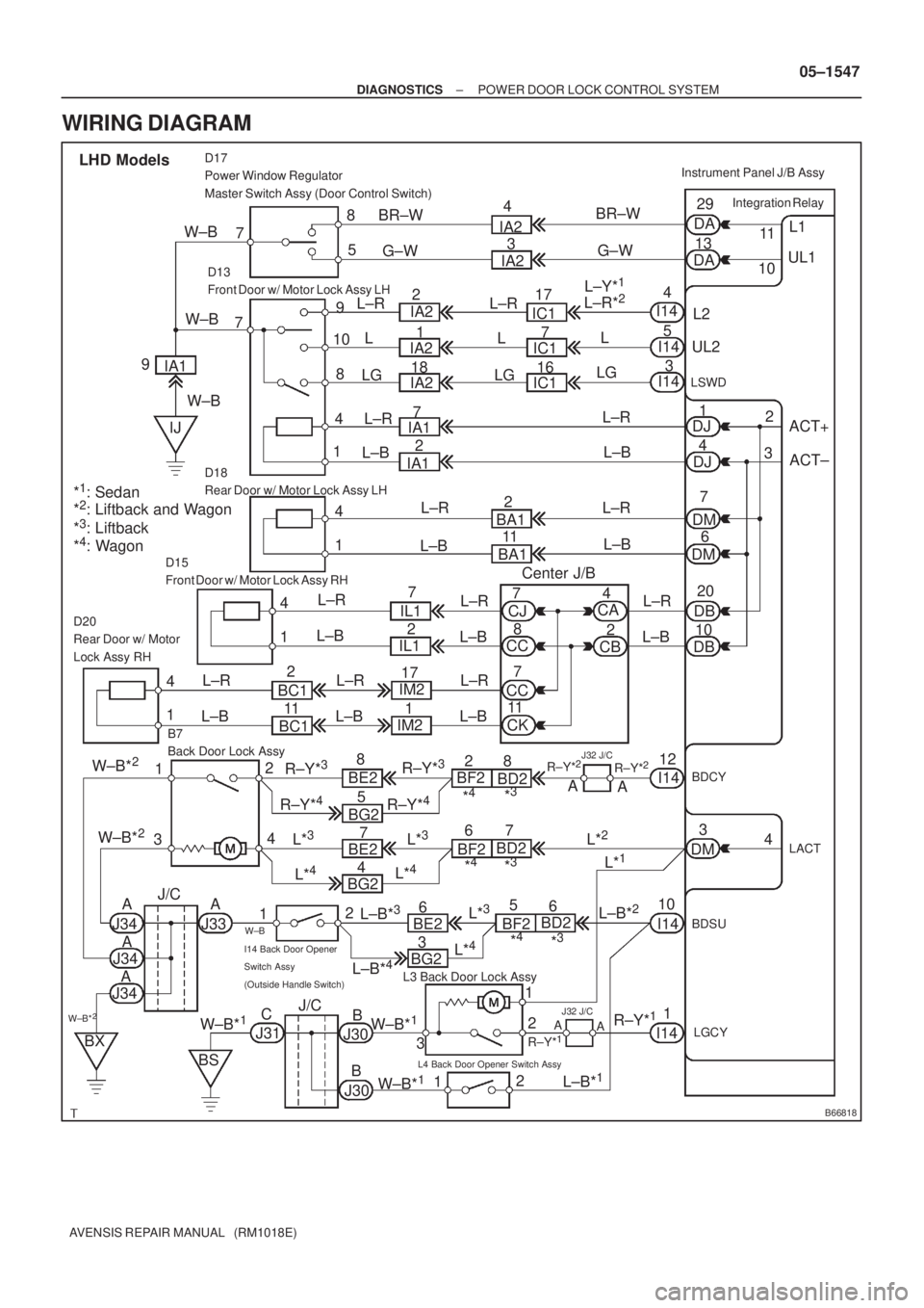
B66818
ACT+ L1
UL1
Integration Relay
DA
DA11
10 29
13
5 8
D17
Power Window Regulator
Master Switch Assy (Door Control Switch)
7
L2 9
10
18
4 7
D13
Front Door w/ Motor Lock Assy LH
UL2
LSWD
ACT±
20
10
D15
Front Door w/ Motor Lock Assy RH
B7
Back Door Lock AssyInstrument Panel J/B Assy
LHD Models
4
5
3
DJ1
DJ4
DM7
DM6
1 4
D18
Rear Door w/ Motor Lock Assy LH
DB
DB 1 4D20
Rear Door w/ Motor
Lock Assy RH
1 4
BDCYI1412
12
4
3
LACT4
DM3
1
2
3 2
12
L3 Back Door Lock Assy
I14 Back Door Opener
Switch Assy
(Outside Handle Switch)
L4 Back Door Opener Switch Assy
LGCY
1
1BDSU
10 W±BBR±W
IA2
IC1
IA1
BA1
CA
CJ
CC
CC
CK IL1
BC1IM2
BE2
BG2R±Y*
3BF2
BD2
J34A
W±B*2J/C
J31 IA1
IJG±W
IA2
IC1
IC1
IA1BR±W
G±W 4
3
17
7
16
7
2
2
11
BA1 L±R
L
L±R
L±B
Center J/B LG
L±R
L±B
L±R
L±B
L±R
L±B L±R
L±B L±R
L±B
BC1IL1
IM2
R±Y*
3
R±Y*4R±Y*4
8
5 2
117
172
1
W±B*2
W±B*2
BE2
5 4
BG27
L*
4
L*3
J34
J34
BX
BS
J30 W±B*
1C
B
B J30W±B*1
W±B*1
A
AA
J33 BE26*
4*3R±Y*
228
A
A
I14
I14
L±B*
1 A
A
J32 J/C
R±Y*1
R±Y*1
L*3BF2BD2
*4*3
7 6
L*2
L*1
BF2BD26
*4*3
CBL±R
L±B
L±R
L±B
8 7
7
112 4
L±R
L±B
L*
4
L±B*3L±B*2L*3
L±R*2L±Y*1
I14
I14
I14 L
LG
2
3
*
1: Sedan
*2: Liftback and Wagon
*3: Liftback
*4: Wagon9W±B
L±R
L±B
R±Y*2
J/C
BG23
L*
4
L±B*4
J32 J/C
L±R
L
LGIA2
IA22
1
18 IA2
W±B
W±B
± DIAGNOSTICSPOWER DOOR LOCK CONTROL SYSTEM
05±1547
AVENSIS REPAIR MANUAL (RM1018E)
WIRING DIAGRAM
Page 1620 of 5135

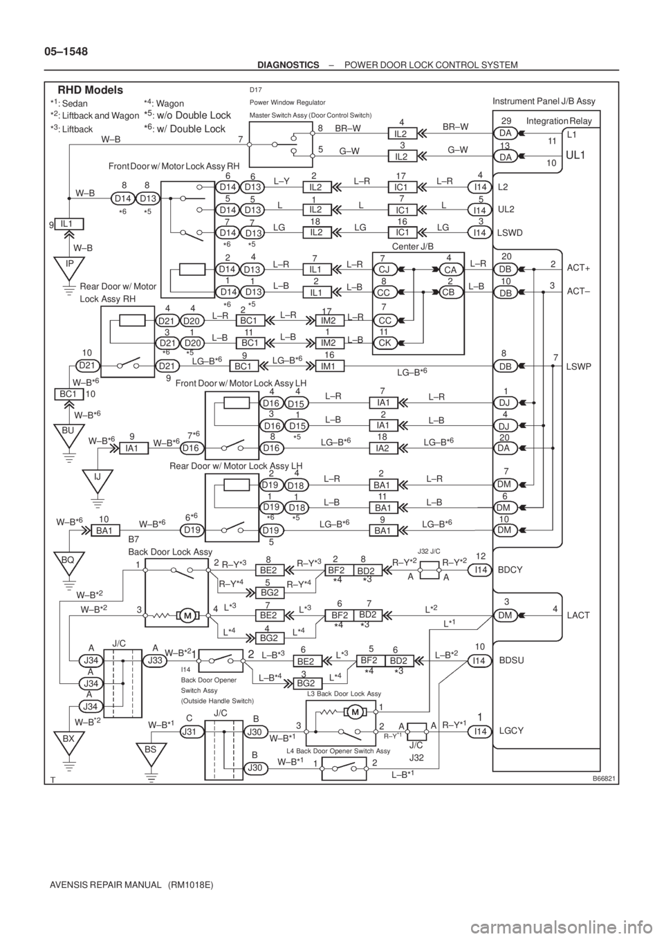
B66821
ACT+ L1
UL1
Integration Relay
DA
DA11
10 29
13
5 8
D17
Power Window Regulator
Master Switch Assy (Door Control Switch)
7
L2 8
7 Front Door w/ Motor Lock Assy RH
UL2
LSWD
ACT± 20
10
Front Door w/ Motor Lock Assy LH
B7
Back Door Lock AssyInstrument Panel J/B Assy
RHD Models
I144
5
3
DJ1
DJ4
DM7
DM6 34 Rear Door w/ Motor
Lock Assy RHDB
DB
Rear Door w/ Motor Lock Assy LH
BDCY I1412
12
4
3
LACT 4
DM3
1
2 3
2
12
L4 Back Door Opener Switch Assy
LGCY
1
1BDSU 10 6
5
76
5
14
1 2D13
D13
D13
D13
D13 D14 D14D14 D14 D14 8
D13 D14
34
D21
D21
D15
D15 D16 D16
1 4 14
D20
D20
D18
D1814
D19
D19 *
5*6
*5: w/o Double Lock
*6: w/ Double Lock
*5*6
*5*6
*5*6
*5
*5*6
IL2
IC1 IL2
IM2
LG±B*
6
IA1
BA1CJ
CC
CKCA
CB 16 BR±W
G±W
L±Y
L
LGIC1
IC1 IL2
7 174
3
G±W BR±W
IL2
IL22
1
18L±R
L
LGL±R
L
LG W±B
9IL1
W±BW±B
IP
L±R
L±BIL1
IL12 7
L±R
L±B
CC7
8
7
11
IM2
IM1 BC1
BC1
BC1 L±R
L±B
D21
9LG±B*
6
LG±B*6
17
1612 4
L±R
L±B
D21
W±B*
6
BC1 10
BU
IJ W±B*
6
W±B*6
IA19 10
D16Center J/B
2
7 3
DB8
LSWP
DA20 7*
6
D168L±R
L±B
LG±B*6
L±R
L±BI14
I14
7
2
18 IA1
IA2LG±B*
6
L±R
L±B
D1912
5L±R
L±B
LG±B*
6
2
11
9 BA1
BA1L±R
L±B
LG±B*
6DM10
D196*
6
W±B*6
W±B*610
BA1 W±B*6
BQ
BXBE2
BG2R±Y*3BF2
BD2
J34
J/C
J31R±Y*3
R±Y*4R±Y*4
8
5
W±B*
2BE2
4
BG27
L*
4
L*3
J30 W±B*
1C
B
B J30
W±B*
1
W±B*1
AJ33
BE26
*4*3R±Y*
228
A
A
L±B*
1
L*3BF2BD2
*4*37 6
L*
2
L*1
BF2
BD26
*4*3 L*
4
L±B*3L±B*2L*3I14
I14 W±B*
2
J/C
I14
Back Door Opener
Switch Assy
(Outside Handle Switch)
BS
L3 Back Door Lock Assy
R±Y
*1
W±B*2
AAA
J34
J345
AAR±Y*
1
*1: Sedan
*2: Liftback and Wagon
*3: Liftback*
4: Wagon
R±Y*
2J32 J/C
3
BG2 L±B*4L*4
W±B*2
L±R
L±B
911 2
J/C
J32
05±1548
± DIAGNOSTICSPOWER DOOR LOCK CONTROL SYSTEM
AVENSIS REPAIR MANUAL (RM1018E)
Page 1621 of 5135

±
DIAGNOSTICS POWER DOOR LOCK CONTROL SYSTEM
05±1549
AVENSIS REPAIR MANUAL (RM1018E)
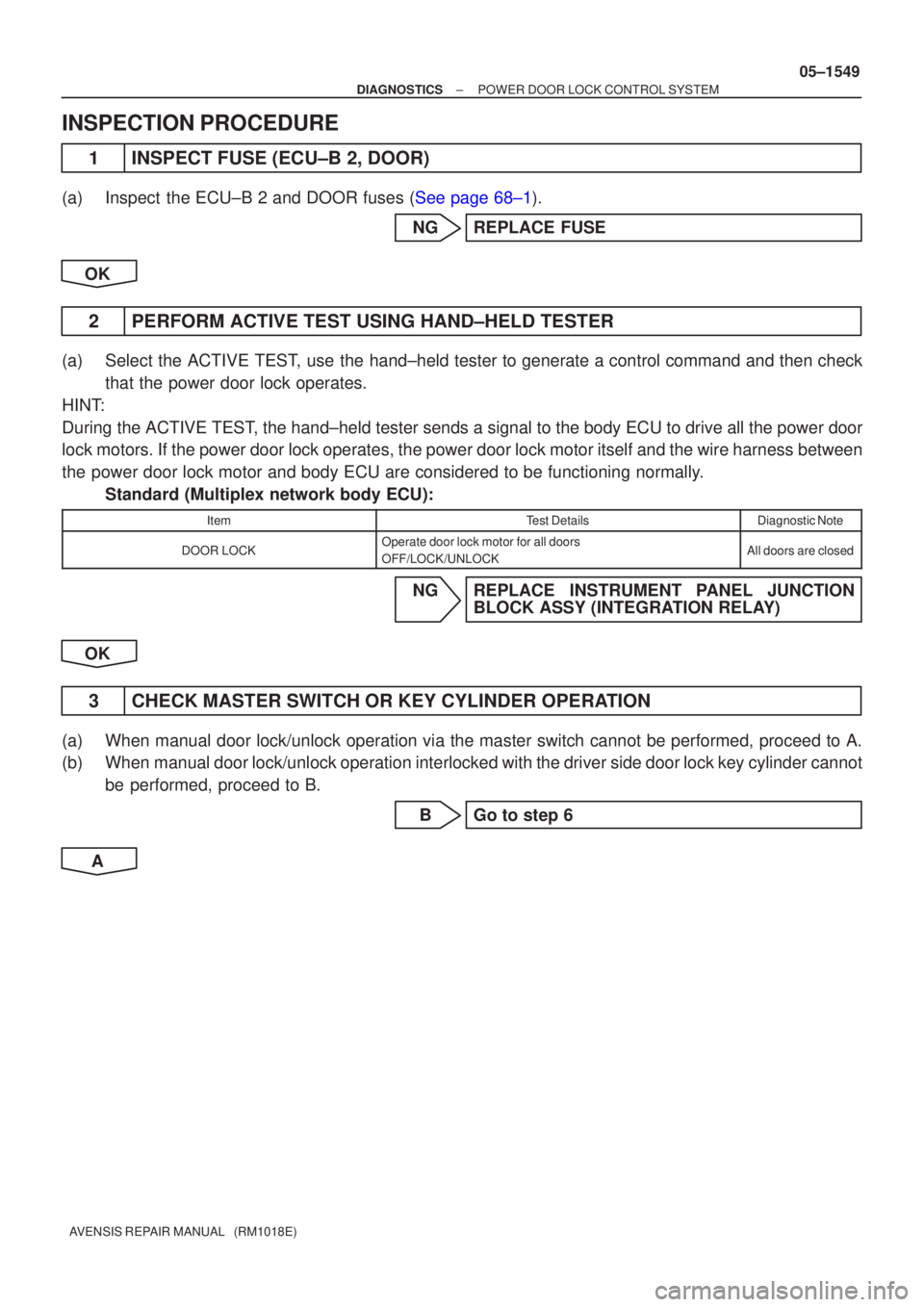
INSPECTION PROCEDURE
1 INSPECT FUSE (ECU±B 2, DOOR)
(a)Inspect the ECU±B 2 and DOOR fuses (See page 68±1).
NG REPLACE FUSE
OK
2 PERFORM ACTIVE TEST USING HAND±HELD TESTER
(a) Select the ACTIVE TEST, use the hand±held tester to generate a control command and then check that the power door lock operates.
HINT:
During the ACTIVE TEST, the hand±held tester sends a signal to the body ECU to drive all th\
e power door
lock motors. If the power door lock operates, the power door lock motor itse\
lf and the wire harness between
the power door lock motor and body ECU are considered to be functioning nor\
mally. Standard (Multiplex network body ECU):
ItemTest DetailsDiagnostic Note
DOOR LOCKOperate door lock motor for all doors
OFF/LOCK/UNLOCKAll doors are closed
NG REPLACE INSTRUMENT PANEL JUNCTION BLOCK ASSY (INTEGRATION RELAY)
OK
3 CHECK MASTER SWITCH OR KEY CYLINDER OPERATION
(a) When manual door lock/unlock operation via the master switch cannot be p\
erformed, proceed to A.
(b) When manual door lock/unlock operation interlocked with the driver side door\
lock key cylinder cannot be performed, proceed to B.
B Go to step 6
A